1999 DODGE NEON ESP
[x] Cancel search: ESPPage 843 of 1200
oline and up to 17 percent ETBE. Gasoline blended
with MTBE or ETBE may be used in your vehicle.
Methanol- Methanol (Methyl or Wood Alcohol) is
used in a variety of concentrations blended with
unleaded gasoline. You may encounter fuels contain-
ing 3 percent or more methanol along with other
alcohols called cosolvents.
DO NOT USE GASOLINES CONTAINING
METHANOL.
Use of methanol/gasoline blends may result in
starting and driveability problems and damage criti-
cal fuel system components.
Problems that are the result of using methanol/
gasoline blends are not the responsibility of Chrysler
Corporation and may not be covered by the vehicle
warranty.
Reformulated Gasoline
Many areas of the country are requiring the use of
cleaner-burning fuel referred to asReformulatedGasoline. Reformulated gasolines are specially
blended to reduce vehicle emissions and improve air
quality.
Chrysler Corporation strongly supports the use of
reformulated gasolines whenever available. Although
your vehicle was designed to provide optimum perfor-
mance and lowest emissions operating on high qual-
ity unleaded gasoline, it will perform equally well
and produce even lower emissions when operating on
reformulated gasoline.
Materials Added to Fuel
Indiscriminate use of fuel system cleaning agents
should be avoided. Many of these materials intended
for gum and varnish removal may contain active sol-
vents of similar ingredients that can be harmful to
fuel system gasket and diaphragm materials.
14 - 2 FUEL SYSTEMPL
GENERAL INFORMATION (Continued)
Page 862 of 1200

GENERAL INFORMATION
INTRODUCTION
All engines used in this section have a sequential
Multi-Port Electronic Fuel Injection system. The MPI
system is computer regulated and provides precise
air/fuel ratios for all driving conditions. The Power-
train Control Module (PCM) operates the fuel injec-
tion system.
The PCM regulates:
²Ignition timing
²Air/fuel ratio
²Emission control devices
²Cooling fan
²Charging system
²Idle speed
²Vehicle speed control
Various sensors provide the inputs necessary for
the PCM to correctly operate these systems. In addi-
tion to the sensors, various switches also provide
inputs to the PCM.
All inputs to the PCM are converted into signals.
The PCM can adapt its programming to meet chang-
ing operating conditions.
Fuel is injected into the intake port above the
intake valve in precise metered amounts through
electrically operated injectors. The PCM fires the
injectors in a specific sequence. Under most operat-
ing conditions, the PCM maintains an air fuel ratio
of 14.7 parts air to 1 part fuel by constantly adjust-
ing injector pulse width. Injector pulse width is the
length of time the injector is open.
The PCM adjusts injector pulse width by opening
and closing the ground path to the injector. Engine
RPM (speed) and manifold absolute pressure (air
density) are the primary inputs that determine injec-
tor pulse width.
MODES OF OPERATION
As input signals to the PCM change, the PCM
adjusts its response to output devices. For example,
the PCM must calculate a different injector pulse
width and ignition timing for idle than it does for
Wide Open Throttle (WOT). There are several differ-
ent modes of operation that determine how the PCM
responds to the various input signals.
There are two different areas of operation, OPEN
LOOP and CLOSED LOOP.
During OPEN LOOP modes the PCM receives
input signals and responds according to preset PCM
programming. Inputs from the upstream and down-
stream heated oxygen sensors are not monitored dur-
ing OPEN LOOP modes, except for heated oxygen
sensor diagnostics (they are checked for shorted con-
ditions at all times).During CLOSED LOOP modes the PCM monitors
the inputs from the upstream and downstream
heated oxygen sensors. The upstream heated oxygen
sensor input tells the PCM if the calculated injector
pulse width resulted in the ideal air-fuel ratio of 14.7
to one. By monitoring the exhaust oxygen content
through the upstream heated oxygen sensor, the
PCM can fine tune injector pulse width. Fine tuning
injector pulse width allows the PCM to achieve opti-
mum fuel economy combined with low emissions.
For the PCM to enter CLOSED LOOP operation,
the following must occur:
(1) Engine coolant temperature must be over 35ÉF.
²If the coolant is over 35É the PCM will wait 44
seconds.
²If the coolant is over 50ÉF the PCM will wait 38
seconds.
²If the coolant is over 167ÉF the PCM will wait
11 seconds.
(2) For other temperatures the PCM will interpo-
late the correct waiting time.
(3) O2 sensor must read either greater than .745
volts or less than .1 volt.
(4) The multi-port fuel injection systems has the
following modes of operation:
²Ignition switch ON (Zero RPM)
²Engine start-up
²Engine warm-up
²Cruise
²Idle
²Acceleration
²Deceleration
²Wide Open Throttle
²Ignition switch OFF
(5) The engine start-up (crank), engine warm-up,
deceleration with fuel shutoff and wide open throttle
modes are OPEN LOOP modes. Under most operat-
ing conditions, the acceleration, deceleration (with
A/C on), idle and cruise modes,with the engine at
operating temperatureare CLOSED LOOP modes.
IGNITION SWITCH ON (ZERO RPM) MODE
When the ignition switch activates the fuel injec-
tion system, the following actions occur:
²The PCM monitors the engine coolant tempera-
ture sensor and throttle position sensor input. The
PCM determines basic fuel injector pulse width from
this input.
²The PCM determines atmospheric air pressure
from the MAP sensor input to modify injector pulse
width.
When the key is in the ON position and the engine
is not running (zero rpm), the Auto Shutdown (ASD)
and fuel pump relays de-energize after approximately
1 second. Therefore, battery voltage is not supplied to
the fuel pump, ignition coil, fuel injectors and heated
oxygen sensors.
PLFUEL SYSTEM 14 - 21
Page 864 of 1200

below the minimum acceptable percentage, the PCM
stores a diagnostic trouble code in memory.
During certain idle conditions, the PCM may enter
a variable idle speed strategy. During variable idle
speed strategy the PCM adjusts engine speed based
on the following inputs.
²A/C sense
²Battery voltage
²Battery temperature
²Engine coolant temperature
²Engine run time
²Power steering pressure switch
²Vehicle mileage
ACCELERATION MODE
This is a CLOSED LOOP mode. The PCM recog-
nizes an abrupt increase in Throttle Position sensor
output voltage or MAP sensor output voltage as a
demand for increased engine output and vehicle
acceleration. The PCM increases injector pulse width
in response to increased fuel demand.
DECELERATION MODE
This is a CLOSED LOOP mode. During decelera-
tion the following inputs are received by the PCM:
²A/C pressure transducer
²A/C sense
²Battery voltage
²Intake air temperature
²Engine coolant temperature
²Crankshaft position (engine speed)
²Exhaust gas oxygen content (upstream heated
oxygen sensor)
²Knock sensor
²Manifold absolute pressure
²Power steering pressure switch
²Throttle position
²IAC motor control changes in respones to MAP
sensor feedback
The PCM may receive a closed throttle input from
the Throttle Position Sensor (TPS) when it senses an
abrupt decrease in manifold pressure. This indicates
a hard deceleration. In response, the PCM may
momentarily turn off the injectors. This helps
improve fuel economy, emissions and engine braking.
If decel fuel shutoff is detected, downstream oxy-
gen sensor diagnostics is performed.
WIDE-OPEN-THROTTLE MODE
This is an OPEN LOOP mode. During wide-open-
throttle operation, the following inputs are received
by the PCM:
²Intake air temperature
²Engine coolant temperature
²Engine speed
²Knock sensor
²Manifold absolute pressure²Throttle position
When the PCM senses a wide-open-throttle condi-
tion through the Throttle Position Sensor (TPS) it de-
energizes the A/C compressor clutch relay. This
disables the air conditioning system.
The PCM does not monitor the heated oxygen sen-
sor inputs during wide-open-throttle operation except
for downstream heated oxygen sensor and both
shorted diagnostics. The PCM adjusts injector pulse
width to supply a predetermined amount of addi-
tional fuel.
IGNITION SWITCH OFF MODE
When the operator turns the ignition switch to the
OFF position, the following occurs:
²All outputs are turned off, unless 02 Heater
Monitor test is being run. Refer to Group 25,
On-Board Diagnostics.
²No inputs are monitored except for the heated
oxygen sensors. The PCM monitors the heating ele-
ments in the oxygen sensors and then shuts down.
DESCRIPTION AND OPERATION
SYSTEM DIAGNOSIS
The PCM can test many of its own input and out-
put circuits. If the PCM senses a fault in a major
system, the PCM stores a Diagnostic Trouble Code
(DTC) in memory.
For DTC information, refer to Group 25, Emission
Control Systems. See On-Board Diagnostics.
POWER DISTRIBUTION CENTER
The power distribution center (PDC) is located next
to the battery (Fig. 1). The PDC contains the starter
relay, radiator fan relay, A/C compressor clutch relay,
auto shutdown relay, fuel pump relay and several
fuses.
Fig. 1 Power Distribution Center (PDC)
PLFUEL SYSTEM 14 - 23
GENERAL INFORMATION (Continued)
Page 870 of 1200
As Intake Air temperature varies the Intake Air
Temperature sensors resistance changes resulting in
a different input voltage to the PCM.
The IAT sensor and Manifold Absolute Pressure
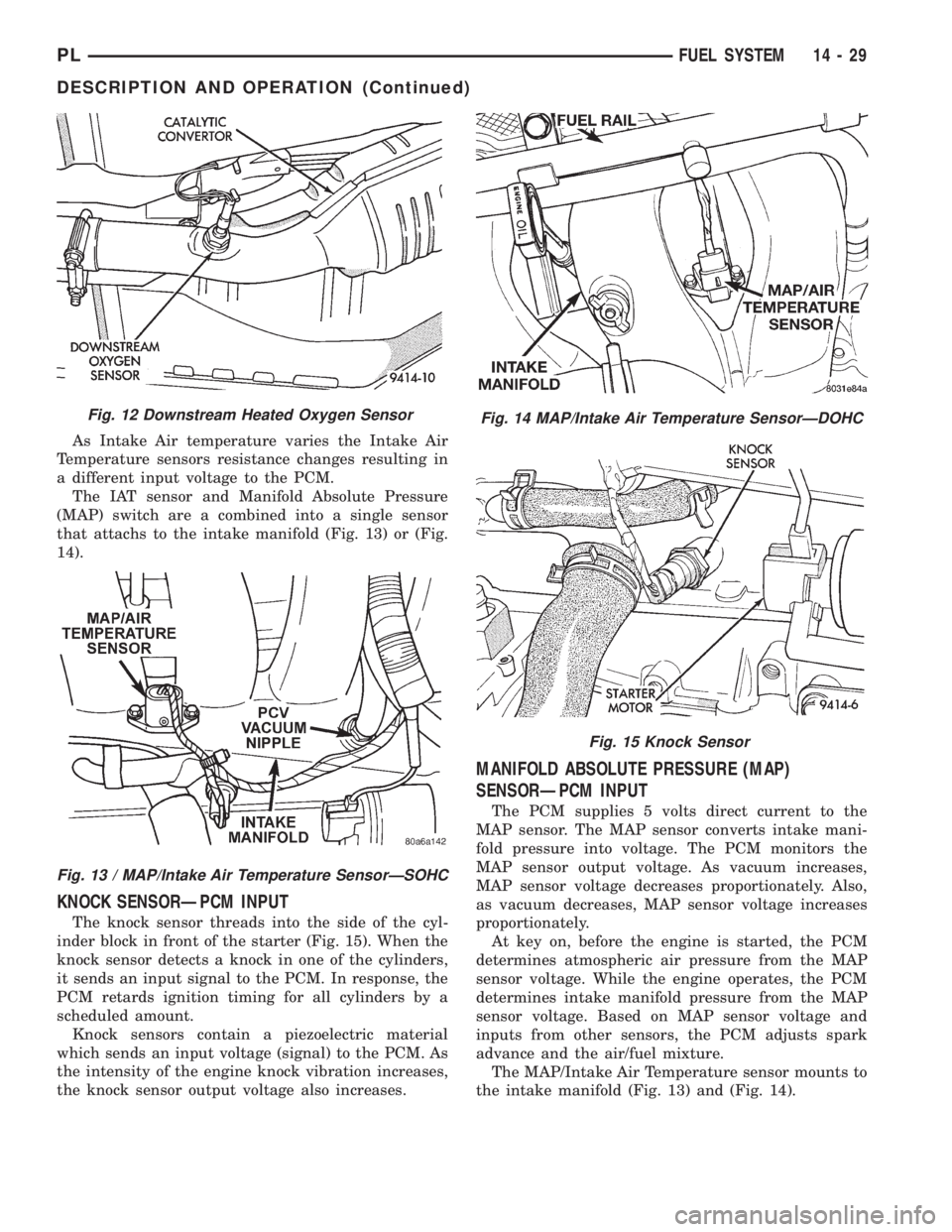
(MAP) switch are a combined into a single sensor
that attachs to the intake manifold (Fig. 13) or (Fig.
14).
KNOCK SENSORÐPCM INPUT
The knock sensor threads into the side of the cyl-
inder block in front of the starter (Fig. 15). When the
knock sensor detects a knock in one of the cylinders,
it sends an input signal to the PCM. In response, the
PCM retards ignition timing for all cylinders by a
scheduled amount.
Knock sensors contain a piezoelectric material
which sends an input voltage (signal) to the PCM. As
the intensity of the engine knock vibration increases,
the knock sensor output voltage also increases.
MANIFOLD ABSOLUTE PRESSURE (MAP)
SENSORÐPCM INPUT
The PCM supplies 5 volts direct current to the
MAP sensor. The MAP sensor converts intake mani-
fold pressure into voltage. The PCM monitors the
MAP sensor output voltage. As vacuum increases,
MAP sensor voltage decreases proportionately. Also,
as vacuum decreases, MAP sensor voltage increases
proportionately.
At key on, before the engine is started, the PCM
determines atmospheric air pressure from the MAP
sensor voltage. While the engine operates, the PCM
determines intake manifold pressure from the MAP
sensor voltage. Based on MAP sensor voltage and
inputs from other sensors, the PCM adjusts spark
advance and the air/fuel mixture.
The MAP/Intake Air Temperature sensor mounts to
the intake manifold (Fig. 13) and (Fig. 14).
Fig. 12 Downstream Heated Oxygen Sensor
Fig. 13 / MAP/Intake Air Temperature SensorÐSOHC
Fig. 14 MAP/Intake Air Temperature SensorÐDOHC
Fig. 15 Knock Sensor
PLFUEL SYSTEM 14 - 29
DESCRIPTION AND OPERATION (Continued)
Page 876 of 1200

send incorrect signals. The PCM substitutes for the
incorrect signals with inputs from other sensors.
If the PCM detects active engine misfire severe
enough to cause catalyst damage, it flashes the MIL.
At the same time the PCM also sets a Diagnostic
Trouble Code (DTC).
For signals that can trigger the MIL (Check
Engine Lamp) refer to Group 25, On-Board
Dianostics.
SOLID STATE FAN RELAYÐPCM OUTPUT
The radiator fan runs when coolant temperature
and A/C system pressure demand cooling. The radia-
tor fan circuit contains a Solid State Fan Relay
(SSFR). Refer to the Group 8W for a circuit sche-
matic.
A 5 volt signal is supplied to the SSFR. The PCM
provides a pulsed ground for the SSFR. Depending
upon the amount of pulse on time, the SSFR puts out
a proportional voltage to the fan motor at the lower
speed. For instance, if the on time is 30 percent, then
the voltage to the fan motor will be 3.6 volts.
When engine coolant reaches approximately 99ÉC
(210ÉF) the PCM grounds the SSFR relay. When the
PCM grounds the relay it operates at a 30% duty
cycle and immediately ramps up to 100% duty cycle.
The PCM de-energizes the SSFR relay when coolant
temperature drops to approximately 93ÉC (199ÉF).
Also, when the air conditioning pressure switch
closes, the PCM grounds the SSFR. The air condi-
tioning switch closes at 285 psi610 psi. When air
conditioning pressure drops approximately 40 psi, the
pressure switch opens and the fan turns off.
The SSFR relay is located on the left front inner
frame just behind the radiator.
SPEED CONTROLÐPCM INPUT
The speed control system provides five separate
voltages (inputs) to the Powertrain Control Module
(PCM). The voltages correspond to the ON/OFF, SET,
RESUME and CANCEL.
The speed control ON voltage informs the PCM
that the speed control system has been activated.
The speed control SET voltage informs the PCM that
a fixed vehicle speed has been selected. The speed
control RESUME voltage indicates the previous fixed
speed is requested. The speed control CANCEL volt-
age tells the PCM to deactivate but retain set speed
in memory (same as depressing the brake pedal). The
speed control OFF voltage tells the PCM that the
speed control system has deactivated. Refer to Group
8H for more speed control information.
SCI RECEIVEÐPCM OUTPUT
SCI Receive is the serial data communication
receive circuit for the DRB scan tool. The Powertrain
Control Module (PCM) receives data from the DRB
through the SCI Receive circuit.
TACHOMETERÐPCM OUTPUT
The PCM operates the tachometer on the instru-
ment panel. The PCM calculates engine RPM from
the crankshaft position sensor input.
TORQUE CONVERTOR CLUTCH SOLENOIDÐPCM
OUTPUT
Three-speed automatic transaxles use a torque con-
verter clutch solenoid. The PCM controls the engage-
ment of the torque converter clutch through the
solenoid (Fig. 29). The torque converter clutch is
engaged up only in direct drive mode. Refer to Group
21 for transmission information.
DIAGNOSIS AND TESTING
VISUAL INSPECTIONÐSOHC
Before diagnosing or servicing the fuel injection
system, perform a visual inspection for loose, discon-
nected, or misrouted wires and hoses (Fig. 30). A
thorough visual inspection that includes the following
checks saves unnecessary test and diagnostic time.
(1) Inspect the battery connections. Clean corroded
terminals (Fig. 31).
(2) Check the 2 PCM 40-way connector for
stretched wires on pushed out terminals (Fig. 31).
Fig. 29 Torque Convertor Clutch Solenoid
PLFUEL SYSTEM 14 - 35
DESCRIPTION AND OPERATION (Continued)
Page 997 of 1200
(3) Move selector lever on transaxle two detents
forward from full rearward position. This is selector
D position.
(4) Read pressures on both gauges as throttle lever
on transaxle is moved from full clockwise to the full
counterclockwise position.
(5) Line pressure should read 52 to 58 psi with
throttle lever clockwise. Pressure should gradually
increase to 80 to 88 psi. as lever is moved counter-
clockwise.
(6) Kickdown release is pressurized only in direct
drive and should be same as line pressure within 3
psi, up to kickdown point.
(7) This tests pump output, pressure regulation,
and condition of rear clutch, front clutch, and
hydraulic circuits.
TEST FOUR (SELECTOR IN REVERSE)
(1) Attach 300 psi gauge to low-reverse port.
(2) Operate engine at 1600 rpm for test.
(3) Move selector lever on transaxle four detents
forward from full rearward position. This is selector
R position.
(4) Low/reverse pressure should read 180 to 220
psi with throttle lever clockwise. Pressure should
gradually increase to 260 to 300 psi. as lever is
moved counterclockwise.
(5) This tests pump output, pressure regulation,
and condition of front clutch and rear servo hydraulic
circuits.
(6) Move selector lever on transaxle to D position
to check that low/reverse pressure drops to zero.
(7) This tests for leakage into rear servo, due to
case porosity, which can cause reverse band burn out.
TEST RESULT INDICATIONS
(1) If proper line pressure, minimum to maximum,
is found in any one test, the pump and pressure reg-
ulator are working properly.
(2) Low pressure in D, 1, and 2 but correct pres-
sure in R, indicates rear clutch circuit leakage.
(3) Low pressure in D and R, but correct pressure
in 1 indicates front clutch circuit leakage.
(4) Low pressure in R and 1, but correct pressure
in 2 indicates rear servo circuit leakage.
(5) Low line pressure in all positions indicates a
defective pump, a clogged filter, or a stuck pressure
regulator valve.
GOVERNOR PRESSURE
Test only if transaxle shifts at wrong vehicle
speeds when throttle cable is correctly adjusted.
(1) Connect a 0-150 psi pressure gauge to governor
pressure take-off point. It is located at lower right
side of case, below differential cover.
(2) Operate transaxle in third gear to read pres-
sures. The governor pressure should respondsmoothly to changes in mph and should return to 0
to 3 psi when vehicle is stopped. High pressure
(above 3 psi) at standstill will prevent the transaxle
from downshifting.
THROTTLE PRESSURE
No gauge port is provided for throttle pressure.
Incorrect throttle pressure should be suspected if
part throttle upshift speeds are either delayed or
occur too early in relation to vehicle speed. Engine
runaway on shifts can also be an indicator of low
throttle pressure setting, or misadjusted throttle
cable.
In no case should throttle pressure be adjusted
until the transaxle throttle cable adjustment has
been verified to be correct.
CLUTCH AND SERVO AIR PRESSURE TESTS
A no±drive condition might exist even with correct
fluid pressure, because of inoperative clutches or
bands. The inoperative units, clutches, bands, and
servos can be located through a series of tests. This
is done by substituting air pressure for fluid pressure
(Fig. 5).
The front and rear clutches, kickdown servo, and
low/reverse servo can be tested by applying air pres-
sure to their respective passages. To make air pres-
sure tests, proceed as follows:
NOTE: Compressed air supply must be free of all
dirt and moisture. Use a pressure of 30 psi.
Remove oil pan and valve body. Refer to Valve
Body for removal procedure.
FRONT CLUTCH
Apply air pressure to front clutch apply passage
and listen for a dull thud, which indicates that front
clutch is operating. Hold air pressure on for a few
seconds and inspect system for excessive oil leaks.
REAR CLUTCH
Apply air pressure to rear clutch apply passage
and listen for a dull thud, which indicates that rear
clutch is operating. Also, inspect for excessive oil
leaks. If a dull thud cannot be heard in the clutches,
place finger tips on clutch housing and again apply
air pressure. Movement of piston can be felt as the
clutch is applied.
KICKDOWN SERVO (FRONT)
Direct air pressure into KICKDOWN SERVO ON
passage. Operation of servo is indicated by a tighten-
ing of front band. Spring tension on servo piston
should release the band.
21 - 54 TRANSAXLEPL
DIAGNOSIS AND TESTING (Continued)
Page 1071 of 1200
TIRE NOISE OR VIBRATION
Radial-ply tires are sensitive to force impulses
caused by improper mounting, vibration, wheel
defects, or possibly tire imbalance.
To find out if tires are causing the noise or vibra-
tion, drive the vehicle over a smooth road at varying
speeds. Note the noise level during acceleration and
deceleration. The engine, differential and exhaust
noises will change as speed varies, while the tire
noise will usually remain constant.
LEAD CORRECTION CHART
Use the following chart to diagnose a vehicle that
has a complaint of a drift or lead condition. The use
of the chart will help to determine if the lead condi-
tion is the result of a bad tire or is caused by the
front wheel alignment.
SERVICE PROCEDURES
TIRE AND WHEEL ROTATION
NON-DIRECTIONAL TREAD PATTERN TIRES
Tires on the front and rear axles operate at differ-
ent loads and perform different functions. For these
reasons, they wear at unequal rates, and tend to
develop irregular wear patterns. These effects can be
reduced by timely rotation of tires. The benefits of
rotation are especially worthwhile. Rotation will
increase tread life, help to maintain mud, snow, and
wet traction levels, and contribute to a smooth, quiet
ride.
The suggested rotation method is the forward-cross
tire rotation method (Fig. 6). This method takes
advantage of current tire industry practice whichallows rotation of radial-ply tires. Other rotation
methods may be used, but may not have all the ben-
efits of the recommended method.
NOTE: Only the 4 tire rotation method may be used
if the vehicle is equipped with a low mileage or tem-
porary spare tire.
DIRECTIONAL TREAD PATTERN TIRES
Some vehicles are fitted with special high-perfor-
mance tires having a directional tread pattern. These
tires are designed to improve traction on wet pave-
ment. To obtain the full benefits of this design, the
tires must be installed so that they rotate in the cor-
rect direction. This is indicated by arrows on the tire
sidewalls.
When wheels and tires are being installed, extra
care is needed to ensure that this direction of rota-
tion is maintained.
Refer to Owner's Manual for rotation schedule.
REPAIRING TIRE LEAKS
For proper repairing, a radial tire must be removed
from the wheel. Repairs should only be made if the
defect, or puncture, is in the tread area (Fig. 7). The
tire should be replaced if the puncture is located in
the sidewall.
Deflate tire completely before attempting to dis-
mount the tire from the wheel.Use a lubricant
such as a mild soap solution when dismounting
or mounting tire.Use tools free of burrs or sharp
edges which could damage the tire or wheel rim.
Before mounting tire on wheel, make sure all rust
is removed from the rim bead and repaint if neces-
sary.
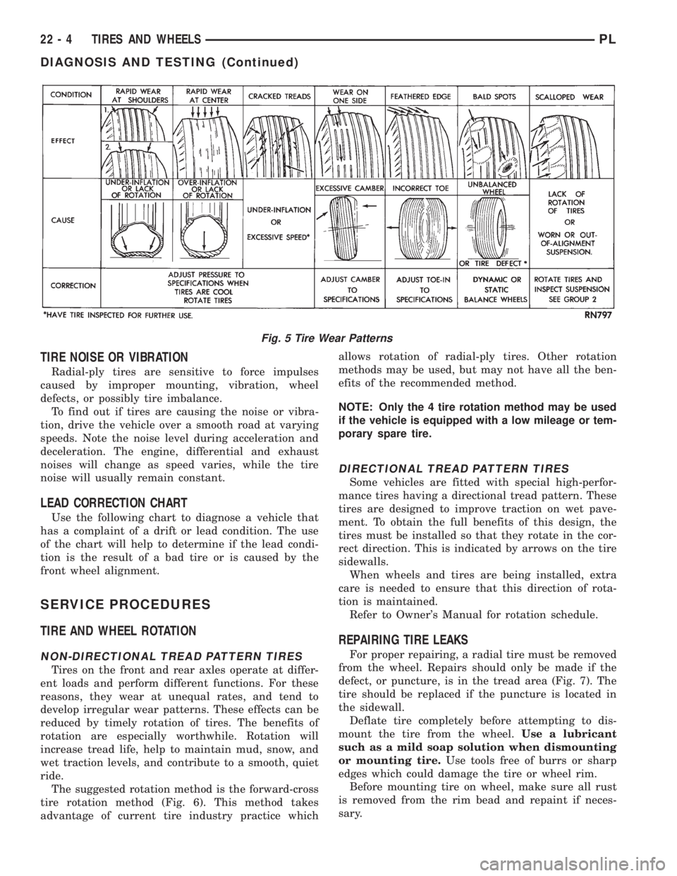
Fig. 5 Tire Wear Patterns
22 - 4 TIRES AND WHEELSPL
DIAGNOSIS AND TESTING (Continued)
Page 1166 of 1200
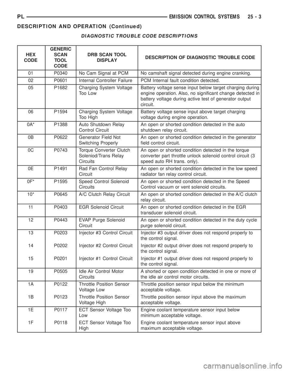
DIAGNOSTIC TROUBLE CODE DESCRIPTIONS
HEX
CODEGENERIC
SCAN
TOOL
CODEDRB SCAN TOOL
DISPLAYDESCRIPTION OF DIAGNOSTIC TROUBLE CODE
01 P0340 No Cam Signal at PCM No camshaft signal detected during engine cranking.
02 P0601 Internal Controller Failure PCM Internal fault condition detected.
05 P1682 Charging System Voltage
Too LowBattery voltage sense input below target charging during
engine operation. Also, no significant change detected in
battery voltage during active test of generator output
circuit.
06 P1594 Charging System Voltage
Too HighBattery voltage sense input above target charging
voltage during engine operation.
0A* P1388 Auto Shutdown Relay
Control CircuitAn open or shorted condition detected in the auto
shutdown relay circuit.
0B P0622 Generator Field Not
Switching ProperlyAn open or shorted condition detected in the generator
field control circuit.
0C P0743 Torque Converter Clutch
Soleniod/Trans Relay
CircuitsAn open or shorted condition detected in the torque
converter part throttle unlock solenoid control circuit (3
speed auto RH trans. only).
0E P1491 Rad Fan Control Relay
CircuitAn open or shorted condition detected in the low speed
radiator fan relay control circuit.
0F* P1595 Speed Control Solenoid
CircuitsAn open or shorted condition detected in the Speed
Control vacuum or vent solenoid circuits.
10* P0645 A/C Clutch Relay Circuit An open or shorted condition detected in the A/C clutch
relay circuit.
11 P0403 EGR Solenoid Circuit An open or shorted condition detected in the EGR
transducer solenoid circuit.
12 P0443 EVAP Purge Solenoid
CircuitAn open or shorted condition detected in the duty cycle
purge solenoid circuit.
13 P0203 Injector #3 Control Circuit Injector #3 output driver does not respond properly to
the control signal.
14 P0202 Injector #2 Control Circuit Injector #2 output driver does not respond properly to
the control signal.
15 P0201 Injector #1 Control Circuit Injector #1 output driver does not respond properly to
the control signal.
19 P0505 Idle Air Control Motor
CircuitsA shorted or open condition detected in one or more of
the idle air control motor circuits.
1A P0122 Throttle Position Sensor
Voltage LowThrottle position sensor input below the minimum
acceptable voltage.
1B P0123 Throttle Position Sensor
Voltage HighThrottle position sensor input above the maximum
acceptable voltage.
1E P0117 ECT Sensor Voltage Too
LowEngine coolant temperature sensor input below
minimum acceptable voltage.
1F P0118 ECT Sensor Voltage Too
HighEngine coolant temperature sensor input above
maximum acceptable voltage.
PLEMISSION CONTROL SYSTEMS 25 - 3
DESCRIPTION AND OPERATION (Continued)