1999 DODGE NEON ESP
[x] Cancel search: ESPPage 159 of 1200
ABS DIAGNOSTIC TROUBLE CODES
Diagnostic trouble codes (DTC) are kept in the con-
troller's memory until either erased by the technician
using the DRB or erased automatically after 3500
miles or 255 key cycles which ever occurs first. DTC's
are retained by the controller even if the ignition isturned off or the battery is disconnected. More than
one DTC can be stored at a time. The key cycle num-
ber of occurrences and the DTC that was stored is
also displayed. Most functions of the CAB and the
ABS system can be accessed by the technician for
testing and diagnostic purposes by using the DRB.
LATCHING VERSUS NON-LATCHING
DIAGNOSTIC TROUBLE CODES
Some DTC's detected by the CAB are latching; the
DTC is latched and ABS braking is disabled until the
ignition switch is reset. Thus ABS braking is non
operational even if the original DTC has disappeared.
Other DTC's are non-latching; any warning lights
that are turned on, are only turned on as long as the
DTC condition exists. As soon as the condition goes
away, the ABS Warning Light is turned off, although
a DTC will be set in most cases.
INTERMITTENT DIAGNOSTIC TROUBLE CODES
As with virtually any electronic system, intermit-
tent electrical problems in the ABS system may be
difficult to accurately diagnose.
Most intermittent electrical problems are caused
by faulty electrical connections or wiring. When an
intermittent fault is encountered, check suspect cir-
cuits for:
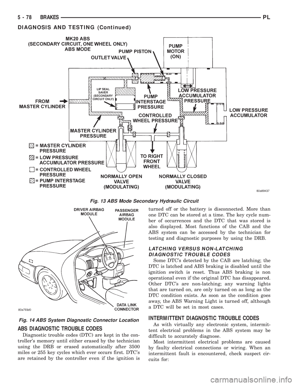
Fig. 13 ABS Mode Secondary Hydraulic Circuit
Fig. 14 ABS System Diagnostic Connector Location
5 - 78 BRAKESPL
DIAGNOSIS AND TESTING (Continued)
Page 161 of 1200
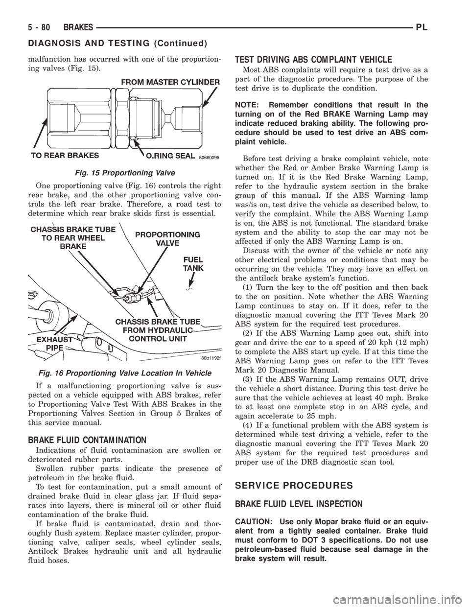
malfunction has occurred with one of the proportion-
ing valves (Fig. 15).
One proportioning valve (Fig. 16) controls the right
rear brake, and the other proportioning valve con-
trols the left rear brake. Therefore, a road test to
determine which rear brake skids first is essential.
If a malfunctioning proportioning valve is sus-
pected on a vehicle equipped with ABS brakes, refer
to Proportioning Valve Test With ABS Brakes in the
Proportioning Valves Section in Group 5 Brakes of
this service manual.
BRAKE FLUID CONTAMINATION
Indications of fluid contamination are swollen or
deteriorated rubber parts.
Swollen rubber parts indicate the presence of
petroleum in the brake fluid.
To test for contamination, put a small amount of
drained brake fluid in clear glass jar. If fluid sepa-
rates into layers, there is mineral oil or other fluid
contamination of the brake fluid.
If brake fluid is contaminated, drain and thor-
oughly flush system. Replace master cylinder, propor-
tioning valve, caliper seals, wheel cylinder seals,
Antilock Brakes hydraulic unit and all hydraulic
fluid hoses.
TEST DRIVING ABS COMPLAINT VEHICLE
Most ABS complaints will require a test drive as a
part of the diagnostic procedure. The purpose of the
test drive is to duplicate the condition.
NOTE: Remember conditions that result in the
turning on of the Red BRAKE Warning Lamp may
indicate reduced braking ability. The following pro-
cedure should be used to test drive an ABS com-
plaint vehicle.
Before test driving a brake complaint vehicle, note
whether the Red or Amber Brake Warning Lamp is
turned on. If it is the Red Brake Warning Lamp,
refer to the hydraulic system section in the brake
group of this manual. If the ABS Warning lamp
was/is on, test drive the vehicle as described below, to
verify the complaint. While the ABS Warning Lamp
is on, the ABS is not functional. The standard brake
system and the ability to stop the car may not be
affected if only the ABS Warning Lamp is on.
Discuss with the owner of the vehicle or note any
other electrical problems or conditions that may be
occurring on the vehicle. They may have an effect on
the antilock brake system's function.
(1) Turn the key to the off position and then back
to the on position. Note whether the ABS Warning
Lamp continues to stay on. If it does, refer to the
diagnostic manual covering the ITT Teves Mark 20
ABS system for the required test procedures.
(2) If the ABS Warning Lamp goes out, shift into
gear and drive the car to a speed of 20 kph (12 mph)
to complete the ABS start up cycle. If at this time the
ABS Warning Lamp goes on refer to the ITT Teves
Mark 20 Diagnostic Manual.
(3) If the ABS Warning Lamp remains OUT, drive
the vehicle a short distance. During this test drive be
sure that the vehicle achieves at least 40 mph. Brake
to at least one complete stop in an ABS cycle, and
again accelerate to 25 mph.
(4) If a functional problem with the ABS system is
determined while test driving a vehicle, refer to the
diagnostic manual covering the ITT Teves Mark 20
ABS system for the required test procedures and
proper use of the DRB diagnostic scan tool.
SERVICE PROCEDURES
BRAKE FLUID LEVEL INSPECTION
CAUTION: Use only Mopar brake fluid or an equiv-
alent from a tightly sealed container. Brake fluid
must conform to DOT 3 specifications. Do not use
petroleum-based fluid because seal damage in the
brake system will result.
Fig. 15 Proportioning Valve
Fig. 16 Proportioning Valve Location In Vehicle
5 - 80 BRAKESPL
DIAGNOSIS AND TESTING (Continued)
Page 163 of 1200
CAUTION: Certain components of the ABS System
are not intended to be serviced individually.
Attempting to remove or disconnect certain system
components may result in improper system opera-
tion. Only those components with approved
removal and installation procedures in this manual
should be serviced.
CAUTION: Brake fluid will damage painted sur-
faces. If brake fluid is spilled on any painted sur-
faces, wash off with water immediately.
CAUTION: When performing any service procedure
on a vehicle equipped with ABS do not apply a 12
volt power source to the ground circuit of the pump
motor in the HCU. Doing this will damage the pump
motor and will require replacement of the entire
HCU.
The following are general cautions which should be
observed when servicing the ABS system and/or
other vehicle systems. Failure to observe these pre-
cautions may result in ABS System component dam-
age.
If welding work is to be performed on the vehicle,
using an electric arc welder, the CAB connector
should be disconnected during the welding operation.
The CAB 25 way connector connector should never
be connected or disconnected with the ignition switch
in the ON position.
Many components of the ABS System are not ser-
viceable and must be replaced as an assembly. Do not
disassemble any component which is not designed to
be serviced.
ABS HYDRAULIC CONTROL UNIT
REMOVE
(1) Disconnect negative (ground) cable from the
battery and isolate cable.
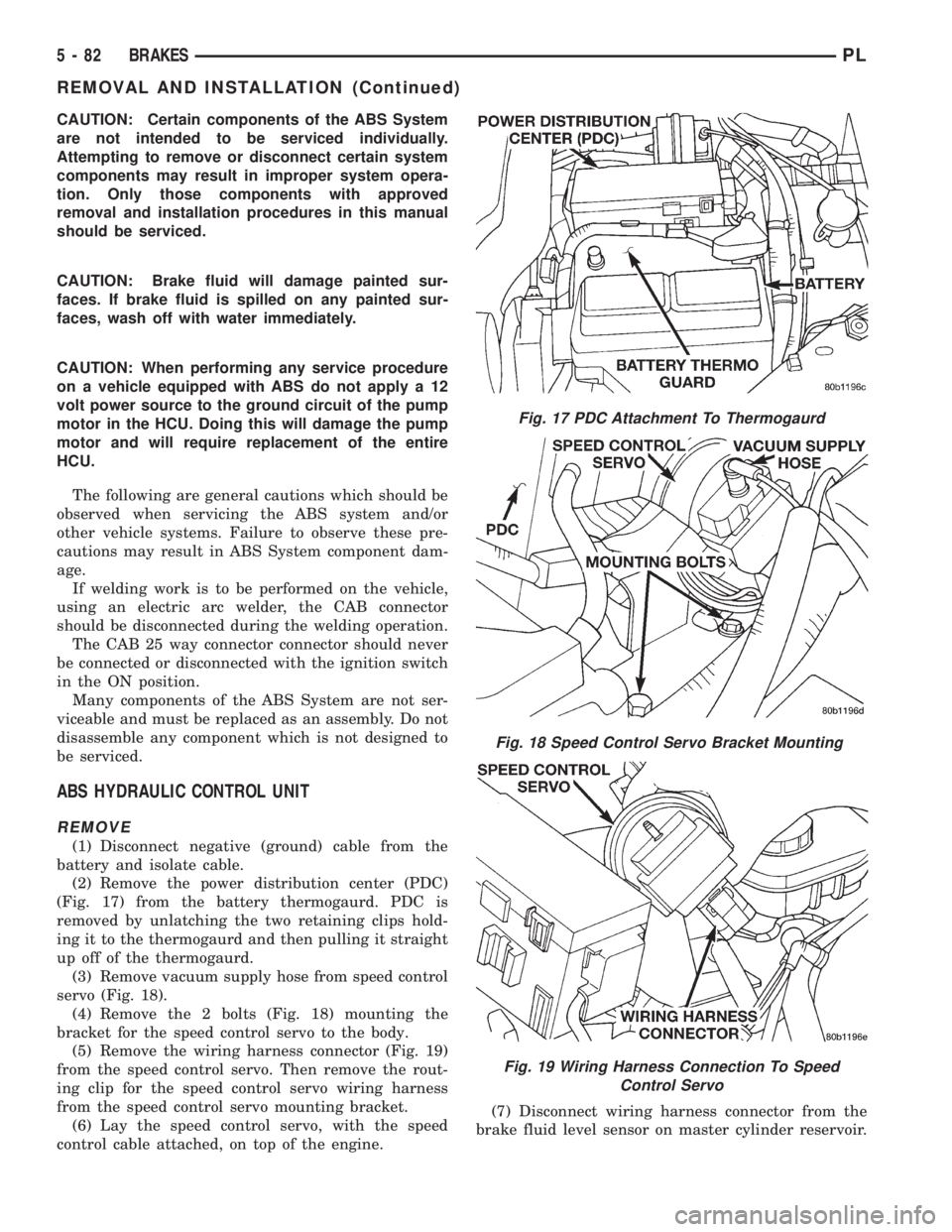
(2) Remove the power distribution center (PDC)
(Fig. 17) from the battery thermogaurd. PDC is
removed by unlatching the two retaining clips hold-
ing it to the thermogaurd and then pulling it straight
up off of the thermogaurd.
(3) Remove vacuum supply hose from speed control
servo (Fig. 18).
(4) Remove the 2 bolts (Fig. 18) mounting the
bracket for the speed control servo to the body.
(5) Remove the wiring harness connector (Fig. 19)
from the speed control servo. Then remove the rout-
ing clip for the speed control servo wiring harness
from the speed control servo mounting bracket.
(6) Lay the speed control servo, with the speed
control cable attached, on top of the engine.(7) Disconnect wiring harness connector from the
brake fluid level sensor on master cylinder reservoir.
Fig. 17 PDC Attachment To Thermogaurd
Fig. 18 Speed Control Servo Bracket Mounting
Fig. 19 Wiring Harness Connection To Speed
Control Servo
5 - 82 BRAKESPL
REMOVAL AND INSTALLATION (Continued)
Page 165 of 1200
INSTALL
(1) Install the ICU on the mounting bracket.
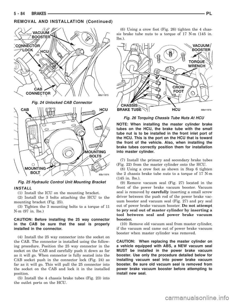
(2) Install the 3 bolts attaching the HCU to the
mounting bracket (Fig. 25).
(3) Tighten the 3 mounting bolts to a torque of 11
N´m (97 in. lbs.)
CAUTION: Before installing the 25 way connector
in the CAB be sure that the seal is properly
installed in the connector.
(4) Install the 25 way connector into the socket on
the CAB. The connector is installed using the follow-
ing procedure. Position the 25 way connector in the
socket on the CAB and carefully push it down as far
as it will go. When connector is fully seated into the
CAB socket push in the connector lock (Fig. 24) as
far as it will go. This will pull the 25 connector into
the socket on the CAB and lock it in the installed
position.
(5) Install the 4 chassis brake tubes (Fig. 23) into
the outlet ports on the HCU.(6) Using a crow foot (Fig. 26) tighten the 4 chas-
sis brake tube nuts to a torque of 17 N´m (145 in.
lbs.).
NOTE: When installing the master cylinder brake
tubes on the HCU, the brake tube with the small
tube nut is to be installed in the front inlet port of
the HCU. This is the port on the HCU that is toward
the front of the vehicle. Also, when installing the
brake tubes correctly position them for installation
into master cylinder.
(7) Install the primary and secondary brake tubes
(Fig. 22) from the master cylinder onto the HCU.
(8) Using a crow foot as shown in Step 6 tighten
the 2 chassis brake tube nuts to a torque of 17 N´m
(145 in. lbs.).
(9) Remove vacuum seal (Fig. 27) located in the
front of the power brake vacuum booster. Vacuum
seal is removed bycarefullyinserting a small screw
driver between the push rod of the power brake vac-
uum booster and vacuum seal (Fig. 27) and pry seal
out of power brake vacuum booster.Do not attempt
to pry seal out of master cylinder by inserting a
tool between seal and power brake vacuum
booster.
(10) Remove old vacuum seal from master cylinder,
if the vacuum seal came out of power brake vacuum
booster when master cylinder was removed.
CAUTION: When replacing the master cylinder on
a vehicle equipped with ABS, a NEW vacuum seal
MUST be installed in the power brake vacuum
booster. Use only the procedure detailed below for
installing vacuum seal into power brake vacuum
booster. Be sure old vacuum seal is removed from
power brake vacuum booster before attempting to
install new seal.
Fig. 24 Unlocked CAB Connector
Fig. 25 Hydraulic Control Unit Mounting Bracket
Fig. 26 Torquing Chassis Tube Nuts At HCU
5 - 84 BRAKESPL
REMOVAL AND INSTALLATION (Continued)
Page 167 of 1200
(18) Install the wiring harness connector (Fig. 19)
on the speed control servo. Then install the routing
clip for the speed control servo wiring harness on the
speed control servo mounting bracket.
Install speed control servo mounting bracket on
body.
(19) Install and securely tighten the 2 bolts (Fig.
18) mounting the bracket for the speed control servo
to the body.
(20) Install the vacuum supply hose on the speed
control servo (Fig. 18).
(21) Install the power distribution center (PDC)
(Fig. 17) on the battery thermogaurd. PDC is install
by pushing straight down on it until the two retain-
ing clips holding it to the thermogaurd are latched to
the thermogaurd.
(22) Connect the negative (ground) cable on the
battery.
(23) Bleed the base brakes and the ABS brakes
hydraulic systems. Refer to Bleeding Base Brake
Hydraulic System in Service Procedures of the Base
Brake Section and Antilock Brakes Hydraulic System
Bleeding Procedure in Service Procedures of the
Antilock Brake Section for the required procedures.
(24) Fill the master cylinder to the proper fill
level.
(25) Road test vehicle to ensure proper operation
of the base and ABS brake systems.
PROPORTIONING VALVES
CAUTION: Proportioning valves should never be
disassembled.
REMOVE
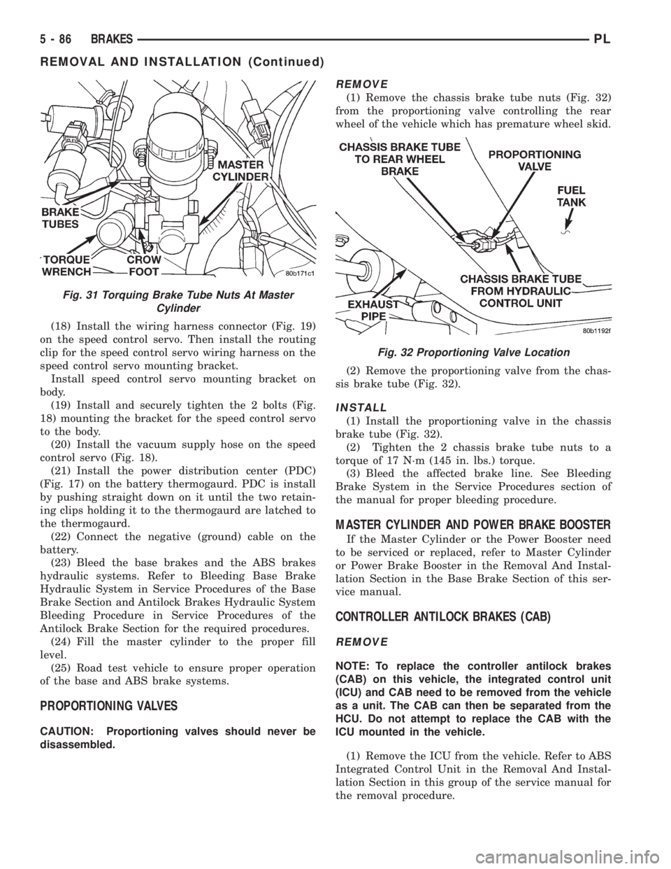
(1) Remove the chassis brake tube nuts (Fig. 32)
from the proportioning valve controlling the rear
wheel of the vehicle which has premature wheel skid.
(2) Remove the proportioning valve from the chas-
sis brake tube (Fig. 32).
INSTALL
(1) Install the proportioning valve in the chassis
brake tube (Fig. 32).
(2) Tighten the 2 chassis brake tube nuts to a
torque of 17 N´m (145 in. lbs.) torque.
(3) Bleed the affected brake line. See Bleeding
Brake System in the Service Procedures section of
the manual for proper bleeding procedure.
MASTER CYLINDER AND POWER BRAKE BOOSTER
If the Master Cylinder or the Power Booster need
to be serviced or replaced, refer to Master Cylinder
or Power Brake Booster in the Removal And Instal-
lation Section in the Base Brake Section of this ser-
vice manual.
CONTROLLER ANTILOCK BRAKES (CAB)
REMOVE
NOTE: To replace the controller antilock brakes
(CAB) on this vehicle, the integrated control unit
(ICU) and CAB need to be removed from the vehicle
as a unit. The CAB can then be separated from the
HCU. Do not attempt to replace the CAB with the
ICU mounted in the vehicle.
(1) Remove the ICU from the vehicle. Refer to ABS
Integrated Control Unit in the Removal And Instal-
lation Section in this group of the service manual for
the removal procedure.
Fig. 31 Torquing Brake Tube Nuts At Master
Cylinder
Fig. 32 Proportioning Valve Location
5 - 86 BRAKESPL
REMOVAL AND INSTALLATION (Continued)
Page 169 of 1200
INSTALL
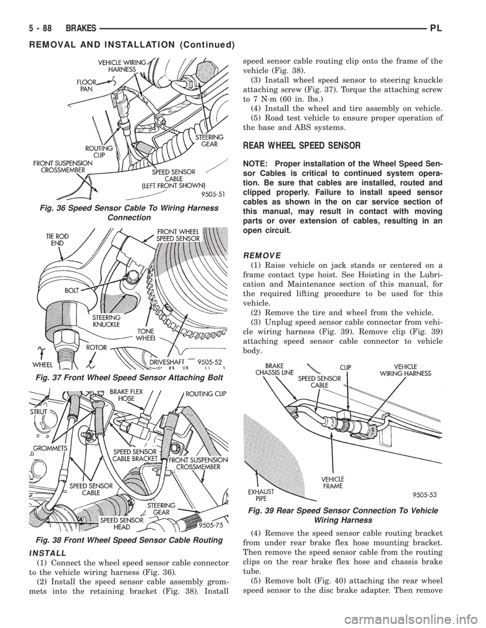
(1) Connect the wheel speed sensor cable connector
to the vehicle wiring harness (Fig. 36).
(2) Install the speed sensor cable assembly grom-
mets into the retaining bracket (Fig. 38). Installspeed sensor cable routing clip onto the frame of the
vehicle (Fig. 38).
(3) Install wheel speed sensor to steering knuckle
attaching screw (Fig. 37). Torque the attaching screw
to 7 N´m (60 in. lbs.)
(4) Install the wheel and tire assembly on vehicle.
(5) Road test vehicle to ensure proper operation of
the base and ABS systems.
REAR WHEEL SPEED SENSOR
NOTE: Proper installation of the Wheel Speed Sen-
sor Cables is critical to continued system opera-
tion. Be sure that cables are installed, routed and
clipped properly. Failure to install speed sensor
cables as shown in the on car service section of
this manual, may result in contact with moving
parts or over extension of cables, resulting in an
open circuit.
REMOVE
(1) Raise vehicle on jack stands or centered on a
frame contact type hoist. See Hoisting in the Lubri-
cation and Maintenance section of this manual, for
the required lifting procedure to be used for this
vehicle.
(2) Remove the tire and wheel from the vehicle.
(3) Unplug speed sensor cable connector from vehi-
cle wiring harness (Fig. 39). Remove clip (Fig. 39)
attaching speed sensor cable connector to vehicle
body.
(4) Remove the speed sensor cable routing bracket
from under rear brake flex hose mounting bracket.
Then remove the speed sensor cable from the routing
clips on the rear brake flex hose and chassis brake
tube.
(5) Remove bolt (Fig. 40) attaching the rear wheel
speed sensor to the disc brake adapter. Then remove
Fig. 36 Speed Sensor Cable To Wiring Harness
Connection
Fig. 37 Front Wheel Speed Sensor Attaching Bolt
Fig. 38 Front Wheel Speed Sensor Cable Routing
Fig. 39 Rear Speed Sensor Connection To Vehicle
Wiring Harness
5 - 88 BRAKESPL
REMOVAL AND INSTALLATION (Continued)
Page 251 of 1200

The major difference between the two engines is
component location which affects the ignition system
service procedures. There are various sensors that
are in different locations due to a different cylinder
head and intake manifold.
The 2.0L engines use a fixed ignition timing sys-
tem. The distributorless electronic ignition system is
referred to as the Direct Ignition System (DIS).
Basic ignition timing is not adjustable.The
Powertrain Control Module (PCM) determines spark
advance. The system's three main components are
the coil pack, crankshaft position sensor, and cam-
shaft position sensor.
POWERTRAIN CONTROL MODULE
The Powertrain Control Module (PCM) controls the
ignition system (Fig. 1). The PCM supplies battery
voltage to the ignition coil through the Auto Shut-
down (ASD) Relay. The PCM also controls the ground
circuit for the ignition coil. By switching the ground
path for the coil on and off, the PCM adjusts ignition
timing to meet changing engine operating conditions.
During the crank-start period the PCM maintains
spark advance at 9É BTDC. During engine operation
the following inputs determine the amount of spark
advance provided by the PCM.
²Intake air temperature
²Coolant temperature
²Engine RPM
²Intake manifold vacuum
²Knock sensor
The PCM also regulates the fuel injection system.
Refer to the Fuel Injection sections of Group 14.
SPARK PLUGS
The 2.0L engines uses resistor spark plugs. For
spark plug identification and specifications, Refer to
the Specifications section at the end of this group.Remove the spark plugs and examine them for
burned electrodes and fouled, cracked or broken por-
celain insulators. Keep plugs arranged in the order
in which they were removed from the engine. An iso-
lated plug displaying an abnormal condition indicates
that a problem exists in the corresponding cylinder.
Replace spark plugs at the intervals recommended in
Group 0.
Spark plugs that have low mileage may be cleaned
and reused if not otherwise defective. Refer to the
Spark Plug Condition section of this group. After
cleaning, file the center electrode flat with a small
point file or jewelers file. Adjust the gap between the
electrodes (Fig. 2) to the dimensions specified in the
chart at the end of this section.
Always tighten spark plugs to the specified torque.
Over tightening can cause distortion and damage.
Tighten spark plugs to 28 N´m (20 ft. lbs.) torque.
SPARK PLUG CABLES
Spark plug cables are sometimes referred to as sec-
ondary ignition wires. The wires transfer electrical
current from the coil pack to individual spark plugs
at each cylinder. The resistor type, nonmetallic spark
plug cables provide suppression of radio frequency
emissions from the ignition system.
Check the spark plug cable connections for good
contact at the coil and spark plugs. Terminals should
be fully seated. The nipples and spark plug covers
should be in good condition. Nipples should fit tightly
on the coil. Spark plug boot should completely cover
the spark plug hole in the cylinder head cover. Install
the boot until the terminal snaps over the spark
plug. A snap must be felt to ensure the spark plug
cable terminal engaged the spark plug.
Loose cable connections will corrode, increase resis-
tance and permit water to enter the coil towers.
These conditions can cause ignition malfunction.
Fig. 1 Powertrain Control Module
Fig. 2 Setting Spark Plug Electrode Gap
8D - 2 IGNITION SYSTEMPL
DESCRIPTION AND OPERATION (Continued)
Page 255 of 1200

SOHC
The coolant sensor threads into the end of the cyl-
inder head, next to the camshaft position sensor (Fig.
12). New sensors have sealant applied to the threads.
DOHC
The coolant sensor threads into the intake mani-
fold next to the thermostat housing (Fig. 13). New
sensors have sealant applied to the threads.
INTAKE AIR TEMPERATURE SENSOR
The intake air temperature sensor measures the
temperature of the air as it enters the engine. The
sensor supplies one of the inputs the PCM uses to
determine injector pulse-width.
The MAP/Intake Air Temperature (IAT) sensor,
located on the intake manifold, combines the MAP
and Intake Air Temperature (IAT) functions into one
sensor (Fig. 14) or (Fig. 15).
KNOCK SENSOR
The knock sensor threads into the side of the cyl-
inder block in front of the starter motor. When the
knock sensor detects a knock in one of the cylinders,
it sends an input signal to the PCM. In response, the
PCM retards ignition timing for all cylinders by a
scheduled amount.
Knock sensors contain a piezoelectric material
which constantly vibrates and sends an input voltage
(signal) to the PCM while the engine operates. As the
intensity of the crystal's vibration increase, the knock
sensor output voltage also increases.
NOTE: Over or under tightening effects knock sen-
sor performance, possibly causing improper spark
control.
MANIFOLD ABSOLUTE PRESSURE SENSOR (MAP)
The PCM supplies 5 volts to the MAP sensor. The
MAP sensor function converts intake manifold pres-
sure into voltage. The PCM monitors the MAP sensor
output voltage. As vacuum increases, MAP sensor
voltage decreases proportionately. Also, as vacuum
decreases, MAP sensor voltage increases proportion-
ately.
Key on, before the engine starts running, the PCM
determines atmospheric air pressure from the MAP
sensor voltage. While the engine operates, the PCM
determines intake manifold pressure from the MAP
sensor voltage. Based on MAP sensor voltage and
inputs from other sensors, the PCM adjusts spark
advance and the air/fuel mixture.
The MAP/IAT sensor mounts to the intake mani-
fold (Fig. 14) or (Fig. 15).
THROTTLE POSITION SENSOR (TPS)
The TPS mounts to the side of the throttle body.
The TPS connects to the throttle blade shaft. The
TPS is a variable resistor that provides the Power-
Fig. 12 Engine Coolant Temperature SensorÐSOHC
Fig. 13 Engine Coolant Temperature SensorÐDOHC
Fig. 14 MAP/IAT sensorÐSOHC
8D - 6 IGNITION SYSTEMPL
DESCRIPTION AND OPERATION (Continued)