1999 DODGE NEON ESP
[x] Cancel search: ESPPage 491 of 1200
POWER
DISTRIBUTION
CENTER
18 17
20A
FUSE
18
9
CONTROLLER
ANTI-LOCK
BRAKE
A17
12
RD/BK
32
BATT A0
D2
18
WT/BK D1
18
VT/BR
2019
1819
1112C101
D1
20
VT/BRD2
20
WT/BK
PAIR TWISTED
25 26
15A
FUSE
25
824
Z1
12
BK BK12Z1
Z1
14
BK
G101 S108
6
5
L50
20
WT/TN
12
L50
18
WT/TN
S101
F32
18
PK/DB
STOP
LAMP
SWITCH
OUTPUT
GROUND GROUND FUSED
B(+) B(+)FUSED
25
RD/DG12 A20 109
40A
FUSE
10
(IN PDC) RELAY
CLUTCH
COMPRESSOR
A/C
DATA
LINK
CONNECTOR
AIRBAG
CONTROL
MODULE
D1
20
VT/BRD2
20
WT/BK
11 3
STOP
LAMP
SWITCH
CCD
BUS
(+) (-)BUS CCD
CCD
BUS
(-) (+) BUS CCD
TPPAIR TWISTED
(8W-10-5)
(8W-10-6)
(8W-10-14)
(8W-10-15)(8W-10-5)
(8W-10-14)
(8W-10-15)
(8W-15-2)
(8W-15-3) (8W-15-2)
(8W-15-3) (8W-30-15) (8W-10-12)
(8W-42-2)
(8W-30-4)
(8W-43-2)
(8W-43-3)(8W-30-15)
8W - 35 - 2 8W-35 ANTI-LOCK BRAKESPL
J988W-18264
Page 493 of 1200
SENSOR SPEED
WHEEL
FRONT
LEFT
LEFT
REAR
WHEEL
SPEED
SENSORRIGHT
FRONT
WHEEL
SPEED
SENSOR
RIGHT
REAR
WHEEL
SPEED
SENSOR
LEFT
FRONT
WHEEL
SPEED
SENSOR
(+)LEFT
FRONT
WHEEL
SPEED
SENSOR
(-) (+)SENSORSPEED WHEELREARLEFT
(-) SENSORSPEED WHEELREARLEFT RIGHT
FRONT
WHEEL
SPEED
SENSOR
(-)RIGHT
FRONT
WHEEL
SPEED
SENSOR
(+) (+)SENSORSPEED WHEELREAR RIGHT
(-) SENSORSPEED WHEELREAR RIGHT
114210183117 B8
18
RD/DB
B9
18
RDB6
18
WT/DBB7
18
VT
B2
20
YL B1
20
YL/DB B3
20
LG/DBB4
20
LG
21
21
21
21
CONTROLLER
ANTI-LOCK
BRAKE
PAIR TWISTED
TWISTED
PAIR
TWISTED
PAIR
PAIR TWISTED
2C10813C1084
B3
18
LG/DBB4
18
LGB1
18
YL/DBB2
18
YL
TWISTED
PAIR
PAIR TWISTED
8W - 35 - 4 8W-35 ANTI-LOCK BRAKESPL
J988W-18266
Page 722 of 1200
(3) Using a black light, inspect the entire engine
for fluorescent dye, particularly at the suspected area
of oil leak. If the oil leak is found and identified,
repair per service manual instructions.
(4) If dye is not observed, drive the vehicle at var-
ious speeds for approximately 24km (15 miles), and
repeat inspection.
(5)If the oil leak source is not positively
identified at this time, proceed with the air leak
detection test method as follows:
(6) Disconnect the fresh air hose (makeup air) at
the cylinder head cover and plug or cap the nipple on
the cover.
(7) Remove the PCV valve hose from the cylinder
head cover. Cap or plug the PCV valve nipple on the
cover.
(8) Attach an air hose with pressure gauge and
regulator to the dipstick tube.
CAUTION: Do not subject the engine assembly to
more than 20.6 kpa (3 PSI) of test pressure.
(9) Gradually apply air pressure from 1 psi to 2.5
psi maximum while applying soapy water at the sus-
pected source. Adjust the regulator to the suitable
test pressure that provide the best bubbles which
will pinpoint the leak source. If the oil leak is
detected and identified, repair per service manual
procedures.
(10) If the leakage occurs at the rear oil seal area,
refer to the section, Inspection for Rear Seal Area
Leak.
(11) If no leaks are detected, turn off the air sup-
ply and remove the air hose and all plugs and caps.
Install the PCV valve and breather cap hose. Proceed
to next step.
(12) Clean the oil off the suspect oil leak area
using a suitable solvent. Drive the vehicle at various
speeds approximately 24 km (15 miles). Inspect the
engine for signs of an oil leak by using a black light.
INSPECTION FOR REAR SEAL AREA LEAKS
Since it is sometimes difficult to determine the
source of an oil leak in the rear seal area of the
engine, a more involved inspection is necessary. Thefollowing steps should be followed to help pinpoint
the source of the leak.
If the leakage occurs at the crankshaft rear oil seal
area:
(1) Disconnect the battery.
(2) Raise the vehicle.
(3) Remove torque converter or clutch housing
cover and inspect rear of block for evidence of oil.
Use a black light to check for the oil leak. If a leak is
present in this area remove transmission for further
inspection.
(a) Circular spray pattern generally indicates
seal leakage or crankshaft damage.
(b) Where leakage tends to run straight down,
possible causes are a porous block, oil galley cup
plug, bedplate to cylinder block mating surfaces
and seal bore. See proper repair procedures for
these items.
(4) If no leaks are detected, pressurized the crank-
case as outlined in the, Inspection (Engine oil Leaks
in general)
CAUTION: Do not exceed 20.6 kPa (3 psi).
(5) If the leak is not detected, very slowly turn the
crankshaft and watch for leakage. If a leak is
detected between the crankshaft and seal while
slowly turning the crankshaft, it is possible the
crankshaft seal surface is damaged. The seal area on
the crankshaft could have minor nicks or scratches
that can be polished out with emery cloth.
CAUTION: Use extreme caution when crankshaft
polishing is necessary to remove minor nicks and
scratches. The crankshaft seal flange is especially
machined to complement the function of the rear oil
seal.
(6) For bubbles that remain steady with shaft
rotation, no further inspection can be done until dis-
assembled.
(7) After the oil leak root cause and appropriate
corrective action have been identified. Refer to Rear
Crankshaft Seals, for proper replacement procedures.
PLENGINE 9 - 9
DIAGNOSIS AND TESTING (Continued)
Page 728 of 1200
inch) maximum. If the cylinder walls are badly
scuffed or scored, the cylinder block should be
rebored and honed, and new pistons and rings fitted.
Whatever type of boring equipment is used, boring
and honing operation should be closely coordinated
with the fitting of pistons and rings in order that
specified clearances may be maintained.Refer to
Honing Cylinder Bores outlined in the Stan-
dard Service Procedures for specification and
procedures.
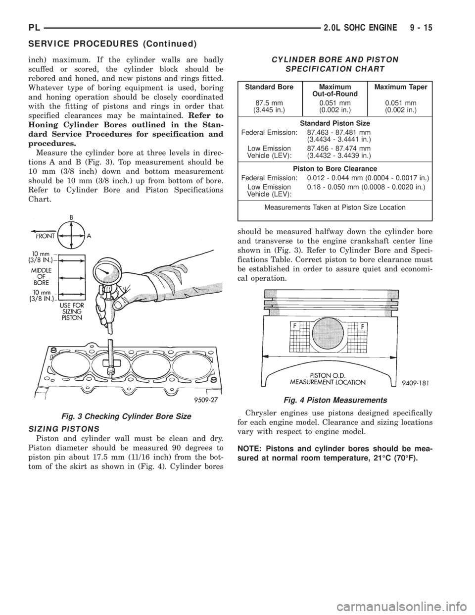
Measure the cylinder bore at three levels in direc-
tions A and B (Fig. 3). Top measurement should be
10 mm (3/8 inch) down and bottom measurement
should be 10 mm (3/8 inch.) up from bottom of bore.
Refer to Cylinder Bore and Piston Specifications
Chart.
SIZING PISTONS
Piston and cylinder wall must be clean and dry.
Piston diameter should be measured 90 degrees to
piston pin about 17.5 mm (11/16 inch) from the bot-
tom of the skirt as shown in (Fig. 4). Cylinder boresshould be measured halfway down the cylinder bore
and transverse to the engine crankshaft center line
shown in (Fig. 3). Refer to Cylinder Bore and Speci-
fications Table. Correct piston to bore clearance must
be established in order to assure quiet and economi-
cal operation.
Chrysler engines use pistons designed specifically
for each engine model. Clearance and sizing locations
vary with respect to engine model.
NOTE: Pistons and cylinder bores should be mea-
sured at normal room temperature, 21ÉC (70ÉF).
Fig. 3 Checking Cylinder Bore Size
CYLINDER BORE AND PISTON
SPECIFICATION CHART
Standard Bore Maximum
Out-of-RoundMaximum Taper
87.5 mm
(3.445 in.)0.051 mm
(0.002 in.)0.051 mm
(0.002 in.)
Standard Piston Size
Federal Emission: 87.463 - 87.481 mm
(3.4434 - 3.4441 in.)
Low Emission
Vehicle (LEV):87.456 - 87.474 mm
(3.4432 - 3.4439 in.)
Piston to Bore Clearance
Federal Emission: 0.012 - 0.044 mm (0.0004 - 0.0017 in.)
Low Emission
Vehicle (LEV):0.18 - 0.050 mm (0.0008 - 0.0020 in.)
Measurements Taken at Piston Size Location
Fig. 4 Piston Measurements
PL2.0L SOHC ENGINE 9 - 15
SERVICE PROCEDURES (Continued)
Page 735 of 1200
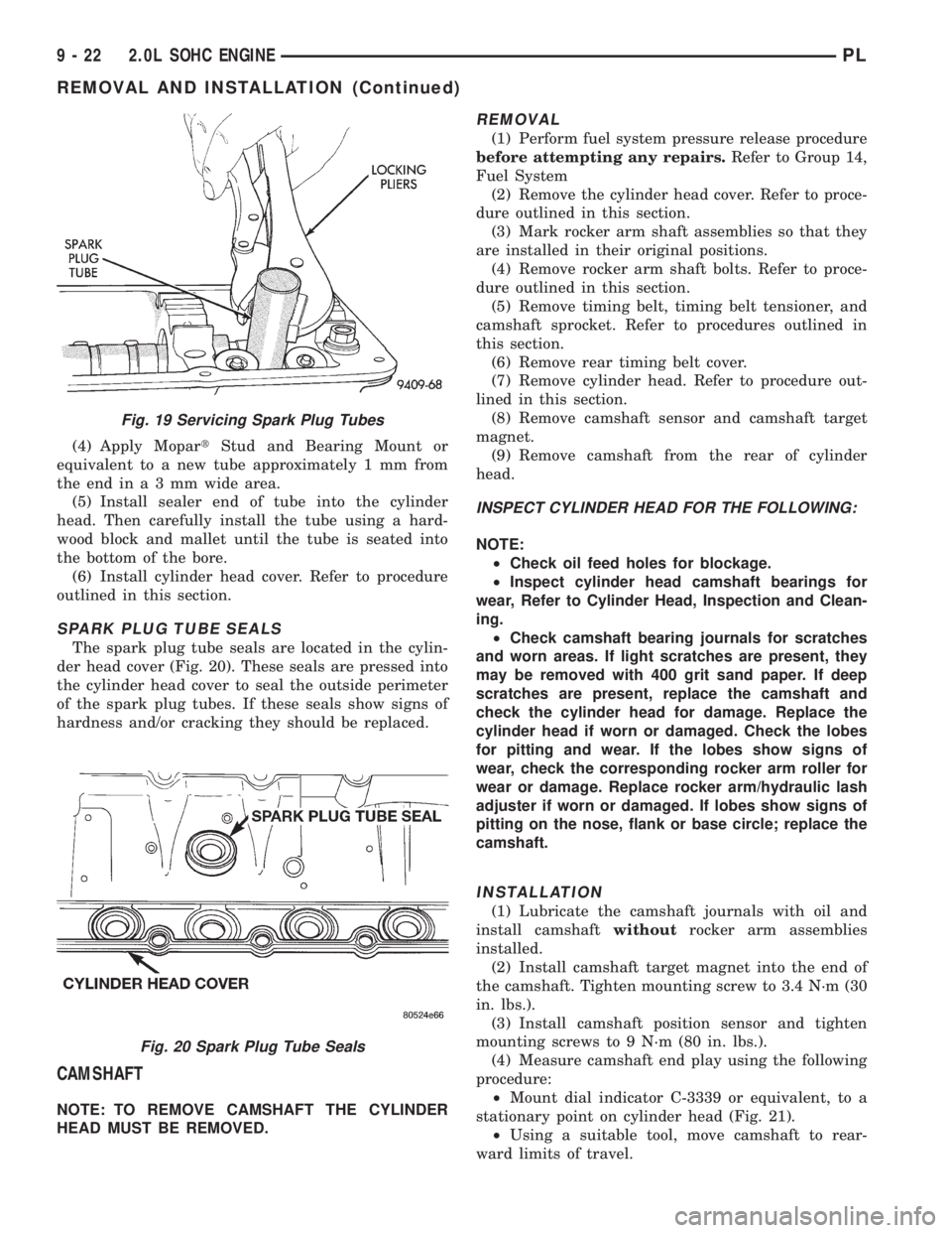
(4) Apply MopartStud and Bearing Mount or
equivalent to a new tube approximately 1 mm from
theendina3mmwide area.
(5) Install sealer end of tube into the cylinder
head. Then carefully install the tube using a hard-
wood block and mallet until the tube is seated into
the bottom of the bore.
(6) Install cylinder head cover. Refer to procedure
outlined in this section.
SPARK PLUG TUBE SEALS
The spark plug tube seals are located in the cylin-
der head cover (Fig. 20). These seals are pressed into
the cylinder head cover to seal the outside perimeter
of the spark plug tubes. If these seals show signs of
hardness and/or cracking they should be replaced.
CAMSHAFT
NOTE: TO REMOVE CAMSHAFT THE CYLINDER
HEAD MUST BE REMOVED.
REMOVAL
(1) Perform fuel system pressure release procedure
before attempting any repairs.Refer to Group 14,
Fuel System
(2) Remove the cylinder head cover. Refer to proce-
dure outlined in this section.
(3) Mark rocker arm shaft assemblies so that they
are installed in their original positions.
(4) Remove rocker arm shaft bolts. Refer to proce-
dure outlined in this section.
(5) Remove timing belt, timing belt tensioner, and
camshaft sprocket. Refer to procedures outlined in
this section.
(6) Remove rear timing belt cover.
(7) Remove cylinder head. Refer to procedure out-
lined in this section.
(8) Remove camshaft sensor and camshaft target
magnet.
(9) Remove camshaft from the rear of cylinder
head.
INSPECT CYLINDER HEAD FOR THE FOLLOWING:
NOTE:
²Check oil feed holes for blockage.
²Inspect cylinder head camshaft bearings for
wear, Refer to Cylinder Head, Inspection and Clean-
ing.
²Check camshaft bearing journals for scratches
and worn areas. If light scratches are present, they
may be removed with 400 grit sand paper. If deep
scratches are present, replace the camshaft and
check the cylinder head for damage. Replace the
cylinder head if worn or damaged. Check the lobes
for pitting and wear. If the lobes show signs of
wear, check the corresponding rocker arm roller for
wear or damage. Replace rocker arm/hydraulic lash
adjuster if worn or damaged. If lobes show signs of
pitting on the nose, flank or base circle; replace the
camshaft.
INSTALLATION
(1) Lubricate the camshaft journals with oil and
install camshaftwithoutrocker arm assemblies
installed.
(2) Install camshaft target magnet into the end of
the camshaft. Tighten mounting screw to 3.4 N´m (30
in. lbs.).
(3) Install camshaft position sensor and tighten
mounting screws to 9 N´m (80 in. lbs.).
(4) Measure camshaft end play using the following
procedure:
²Mount dial indicator C-3339 or equivalent, to a
stationary point on cylinder head (Fig. 21).
²Using a suitable tool, move camshaft to rear-
ward limits of travel.
Fig. 19 Servicing Spark Plug Tubes
Fig. 20 Spark Plug Tube Seals
9 - 22 2.0L SOHC ENGINEPL
REMOVAL AND INSTALLATION (Continued)
Page 763 of 1200
CAUTION: When depressing the valve spring
retainers with valve spring compressor the locks
can become dislocated. Check to make sure both
locks are in their correct location after removing
tool.
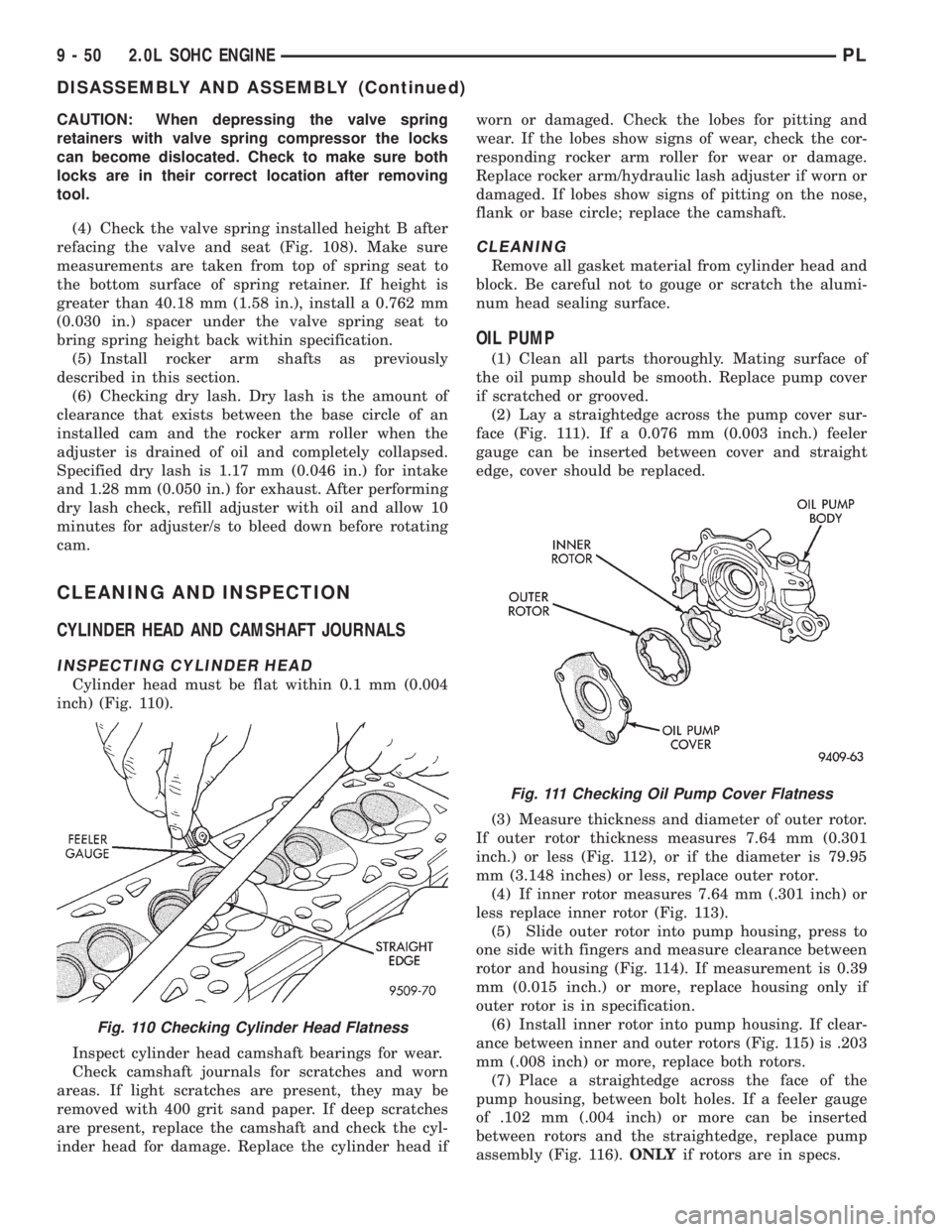
(4) Check the valve spring installed height B after
refacing the valve and seat (Fig. 108). Make sure
measurements are taken from top of spring seat to
the bottom surface of spring retainer. If height is
greater than 40.18 mm (1.58 in.), install a 0.762 mm
(0.030 in.) spacer under the valve spring seat to
bring spring height back within specification.
(5) Install rocker arm shafts as previously
described in this section.
(6) Checking dry lash. Dry lash is the amount of
clearance that exists between the base circle of an
installed cam and the rocker arm roller when the
adjuster is drained of oil and completely collapsed.
Specified dry lash is 1.17 mm (0.046 in.) for intake
and 1.28 mm (0.050 in.) for exhaust. After performing
dry lash check, refill adjuster with oil and allow 10
minutes for adjuster/s to bleed down before rotating
cam.
CLEANING AND INSPECTION
CYLINDER HEAD AND CAMSHAFT JOURNALS
INSPECTING CYLINDER HEAD
Cylinder head must be flat within 0.1 mm (0.004
inch) (Fig. 110).
Inspect cylinder head camshaft bearings for wear.
Check camshaft journals for scratches and worn
areas. If light scratches are present, they may be
removed with 400 grit sand paper. If deep scratches
are present, replace the camshaft and check the cyl-
inder head for damage. Replace the cylinder head ifworn or damaged. Check the lobes for pitting and
wear. If the lobes show signs of wear, check the cor-
responding rocker arm roller for wear or damage.
Replace rocker arm/hydraulic lash adjuster if worn or
damaged. If lobes show signs of pitting on the nose,
flank or base circle; replace the camshaft.
CLEANING
Remove all gasket material from cylinder head and
block. Be careful not to gouge or scratch the alumi-
num head sealing surface.
OIL PUMP
(1) Clean all parts thoroughly. Mating surface of
the oil pump should be smooth. Replace pump cover
if scratched or grooved.
(2) Lay a straightedge across the pump cover sur-
face (Fig. 111). If a 0.076 mm (0.003 inch.) feeler
gauge can be inserted between cover and straight
edge, cover should be replaced.
(3) Measure thickness and diameter of outer rotor.
If outer rotor thickness measures 7.64 mm (0.301
inch.) or less (Fig. 112), or if the diameter is 79.95
mm (3.148 inches) or less, replace outer rotor.
(4) If inner rotor measures 7.64 mm (.301 inch) or
less replace inner rotor (Fig. 113).
(5) Slide outer rotor into pump housing, press to
one side with fingers and measure clearance between
rotor and housing (Fig. 114). If measurement is 0.39
mm (0.015 inch.) or more, replace housing only if
outer rotor is in specification.
(6) Install inner rotor into pump housing. If clear-
ance between inner and outer rotors (Fig. 115) is .203
mm (.008 inch) or more, replace both rotors.
(7) Place a straightedge across the face of the
pump housing, between bolt holes. If a feeler gauge
of .102 mm (.004 inch) or more can be inserted
between rotors and the straightedge, replace pump
assembly (Fig. 116).ONLYif rotors are in specs.
Fig. 110 Checking Cylinder Head Flatness
Fig. 111 Checking Oil Pump Cover Flatness
9 - 50 2.0L SOHC ENGINEPL
DISASSEMBLY AND ASSEMBLY (Continued)
Page 774 of 1200
with the fitting of pistons and rings in order that
specified clearances may be maintained.Refer to
Honing Cylinder Bores outlined in the Stan-
dard Service Procedures for specification and
procedures.
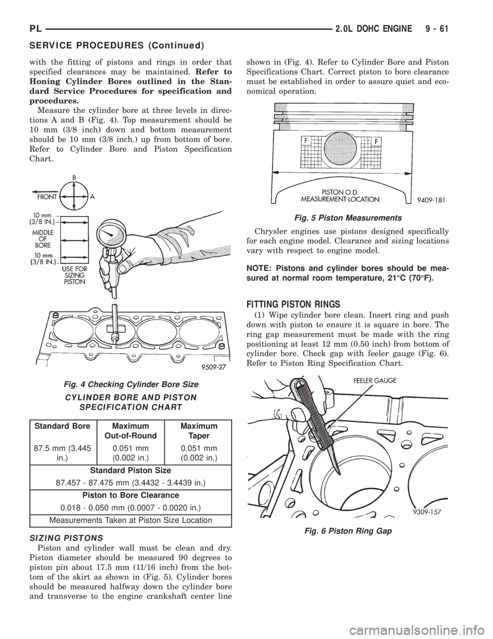
Measure the cylinder bore at three levels in direc-
tions A and B (Fig. 4). Top measurement should be
10 mm (3/8 inch) down and bottom measurement
should be 10 mm (3/8 inch.) up from bottom of bore.
Refer to Cylinder Bore and Piston Specification
Chart.
SIZING PISTONS
Piston and cylinder wall must be clean and dry.
Piston diameter should be measured 90 degrees to
piston pin about 17.5 mm (11/16 inch) from the bot-
tom of the skirt as shown in (Fig. 5). Cylinder bores
should be measured halfway down the cylinder bore
and transverse to the engine crankshaft center lineshown in (Fig. 4). Refer to Cylinder Bore and Piston
Specifications Chart. Correct piston to bore clearance
must be established in order to assure quiet and eco-
nomical operation.
Chrysler engines use pistons designed specifically
for each engine model. Clearance and sizing locations
vary with respect to engine model.
NOTE: Pistons and cylinder bores should be mea-
sured at normal room temperature, 21ÉC (70ÉF).
FITTING PISTON RINGS
(1) Wipe cylinder bore clean. Insert ring and push
down with piston to ensure it is square in bore. The
ring gap measurement must be made with the ring
positioning at least 12 mm (0.50 inch) from bottom of
cylinder bore. Check gap with feeler gauge (Fig. 6).
Refer to Piston Ring Specification Chart.
Fig. 4 Checking Cylinder Bore Size
CYLINDER BORE AND PISTON
SPECIFICATION CHART
Standard Bore Maximum
Out-of-RoundMaximum
Taper
87.5 mm (3.445
in.)0.051 mm
(0.002 in.)0.051 mm
(0.002 in.)
Standard Piston Size
87.457 - 87.475 mm (3.4432 - 3.4439 in.)
Piston to Bore Clearance
0.018 - 0.050 mm (0.0007 - 0.0020 in.)
Measurements Taken at Piston Size Location
Fig. 5 Piston Measurements
Fig. 6 Piston Ring Gap
PL2.0L DOHC ENGINE 9 - 61
SERVICE PROCEDURES (Continued)
Page 807 of 1200
CAUTION: If oversize valves are used, there is only
one oversize valve available. The same stem seal is
used on both the standard and oversize valve.
(3) Install valve springs and retainers. Compress
valve springs only enough to install locks, taking
care not to misalign the direction of compression.
Nicked valve stems may result from misalignment of
the valve spring compressor.
CAUTION: When depressing the valve spring
retainers with valve spring compressor the locks
can become dislocated. Check to make sure both
locks are in their correct location after removing
tool.
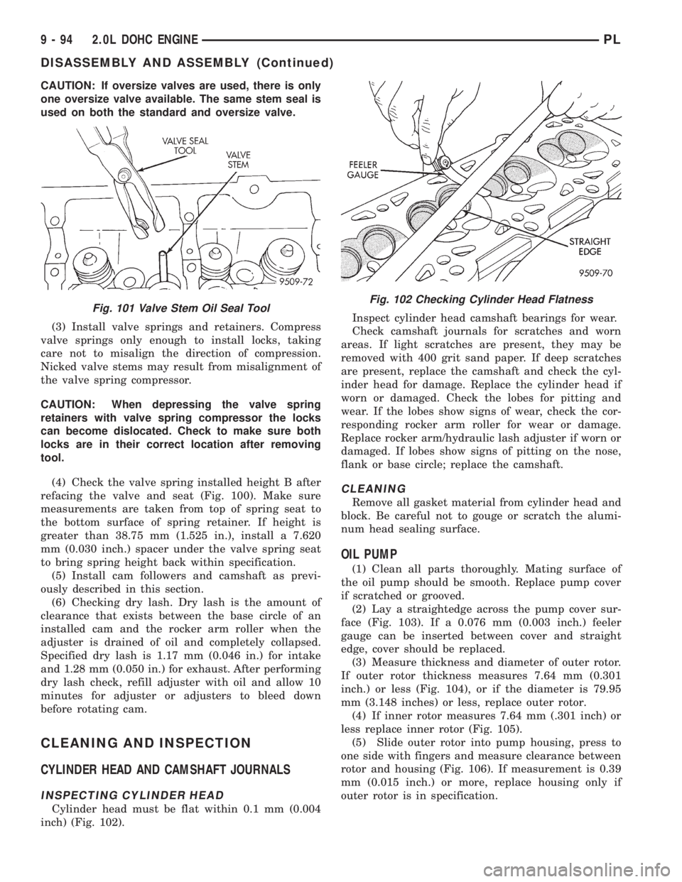
(4) Check the valve spring installed height B after
refacing the valve and seat (Fig. 100). Make sure
measurements are taken from top of spring seat to
the bottom surface of spring retainer. If height is
greater than 38.75 mm (1.525 in.), install a 7.620
mm (0.030 inch.) spacer under the valve spring seat
to bring spring height back within specification.
(5) Install cam followers and camshaft as previ-
ously described in this section.
(6) Checking dry lash. Dry lash is the amount of
clearance that exists between the base circle of an
installed cam and the rocker arm roller when the
adjuster is drained of oil and completely collapsed.
Specified dry lash is 1.17 mm (0.046 in.) for intake
and 1.28 mm (0.050 in.) for exhaust. After performing
dry lash check, refill adjuster with oil and allow 10
minutes for adjuster or adjusters to bleed down
before rotating cam.
CLEANING AND INSPECTION
CYLINDER HEAD AND CAMSHAFT JOURNALS
INSPECTING CYLINDER HEAD
Cylinder head must be flat within 0.1 mm (0.004
inch) (Fig. 102).Inspect cylinder head camshaft bearings for wear.
Check camshaft journals for scratches and worn
areas. If light scratches are present, they may be
removed with 400 grit sand paper. If deep scratches
are present, replace the camshaft and check the cyl-
inder head for damage. Replace the cylinder head if
worn or damaged. Check the lobes for pitting and
wear. If the lobes show signs of wear, check the cor-
responding rocker arm roller for wear or damage.
Replace rocker arm/hydraulic lash adjuster if worn or
damaged. If lobes show signs of pitting on the nose,
flank or base circle; replace the camshaft.
CLEANING
Remove all gasket material from cylinder head and
block. Be careful not to gouge or scratch the alumi-
num head sealing surface.
OIL PUMP
(1) Clean all parts thoroughly. Mating surface of
the oil pump should be smooth. Replace pump cover
if scratched or grooved.
(2) Lay a straightedge across the pump cover sur-
face (Fig. 103). If a 0.076 mm (0.003 inch.) feeler
gauge can be inserted between cover and straight
edge, cover should be replaced.
(3) Measure thickness and diameter of outer rotor.
If outer rotor thickness measures 7.64 mm (0.301
inch.) or less (Fig. 104), or if the diameter is 79.95
mm (3.148 inches) or less, replace outer rotor.
(4) If inner rotor measures 7.64 mm (.301 inch) or
less replace inner rotor (Fig. 105).
(5) Slide outer rotor into pump housing, press to
one side with fingers and measure clearance between
rotor and housing (Fig. 106). If measurement is 0.39
mm (0.015 inch.) or more, replace housing only if
outer rotor is in specification.
Fig. 101 Valve Stem Oil Seal ToolFig. 102 Checking Cylinder Head Flatness
9 - 94 2.0L DOHC ENGINEPL
DISASSEMBLY AND ASSEMBLY (Continued)