1999 DODGE NEON ESP
[x] Cancel search: ESPPage 257 of 1200
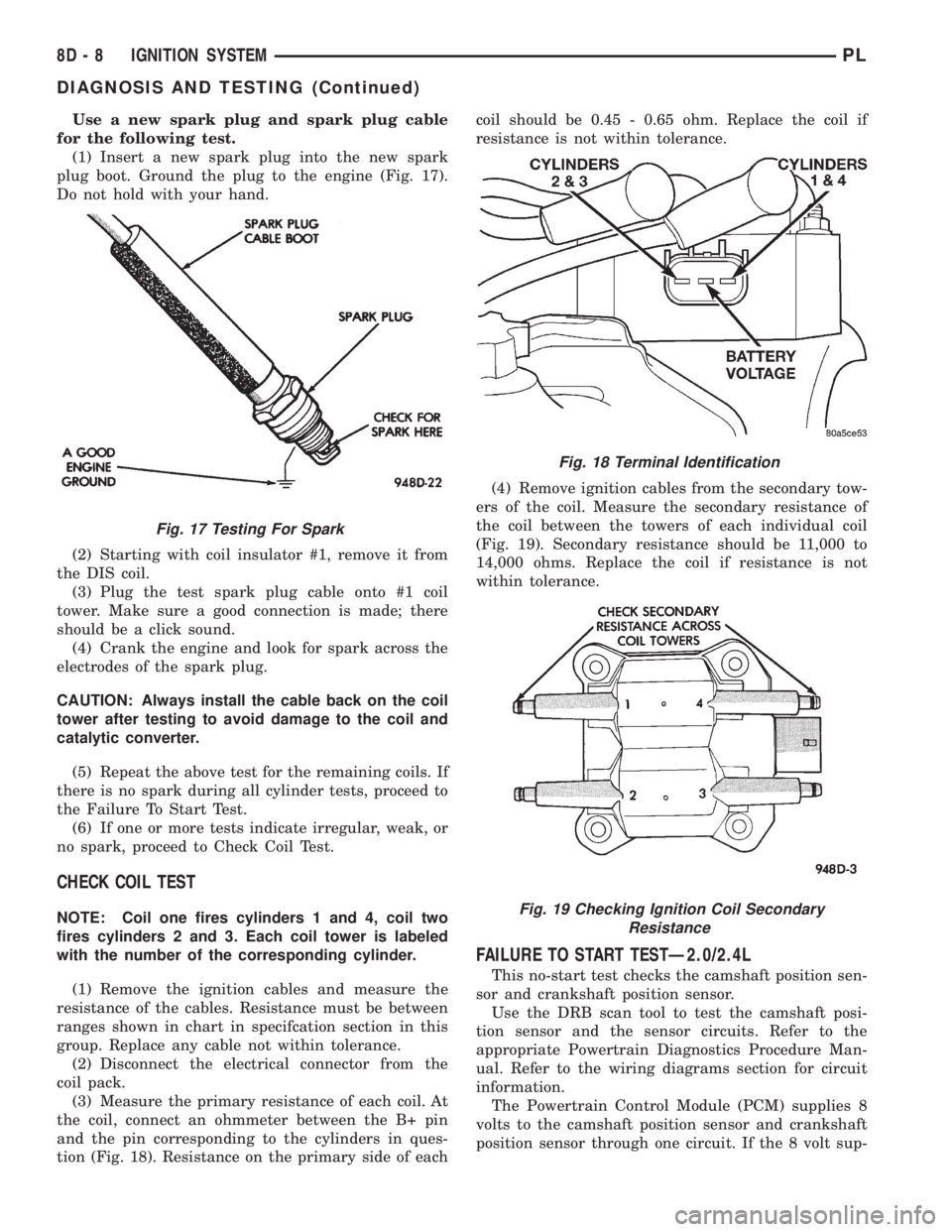
Use a new spark plug and spark plug cable
for the following test.
(1) Insert a new spark plug into the new spark
plug boot. Ground the plug to the engine (Fig. 17).
Do not hold with your hand.
(2) Starting with coil insulator #1, remove it from
the DIS coil.
(3) Plug the test spark plug cable onto #1 coil
tower. Make sure a good connection is made; there
should be a click sound.
(4) Crank the engine and look for spark across the
electrodes of the spark plug.
CAUTION: Always install the cable back on the coil
tower after testing to avoid damage to the coil and
catalytic converter.
(5) Repeat the above test for the remaining coils. If
there is no spark during all cylinder tests, proceed to
the Failure To Start Test.
(6) If one or more tests indicate irregular, weak, or
no spark, proceed to Check Coil Test.
CHECK COIL TEST
NOTE: Coil one fires cylinders 1 and 4, coil two
fires cylinders 2 and 3. Each coil tower is labeled
with the number of the corresponding cylinder.
(1) Remove the ignition cables and measure the
resistance of the cables. Resistance must be between
ranges shown in chart in specifcation section in this
group. Replace any cable not within tolerance.
(2) Disconnect the electrical connector from the
coil pack.
(3) Measure the primary resistance of each coil. At
the coil, connect an ohmmeter between the B+ pin
and the pin corresponding to the cylinders in ques-
tion (Fig. 18). Resistance on the primary side of eachcoil should be 0.45 - 0.65 ohm. Replace the coil if
resistance is not within tolerance.
(4) Remove ignition cables from the secondary tow-
ers of the coil. Measure the secondary resistance of
the coil between the towers of each individual coil
(Fig. 19). Secondary resistance should be 11,000 to
14,000 ohms. Replace the coil if resistance is not
within tolerance.
FAILURE TO START TESTÐ2.0/2.4L
This no-start test checks the camshaft position sen-
sor and crankshaft position sensor.
Use the DRB scan tool to test the camshaft posi-
tion sensor and the sensor circuits. Refer to the
appropriate Powertrain Diagnostics Procedure Man-
ual. Refer to the wiring diagrams section for circuit
information.
The Powertrain Control Module (PCM) supplies 8
volts to the camshaft position sensor and crankshaft
position sensor through one circuit. If the 8 volt sup-
Fig. 17 Testing For Spark
Fig. 18 Terminal Identification
Fig. 19 Checking Ignition Coil Secondary
Resistance
8D - 8 IGNITION SYSTEMPL
DIAGNOSIS AND TESTING (Continued)
Page 296 of 1200
the correct fuse. If the horn fail to sound and the
new fuse blows when depressing the horn switch, a
short circuit in the horn or the horn wiring between
the fuse terminal and the horn is responsible, or a
defective horn switch allowed the horn to burn out is
responsible.
If the fuse is OK, test horn relay refer to Horn
Relay Test.
If the relay is OK, test horn refer to Horn Test.CAUTION: Continuous sounding of horn may
cause horn relay to fail.
Should the horn sound continuously:
²Unplug the horn relay from Power Distribution
Center.
²Refer to Horn Relay Test.
Refer to Group 8W, wiring Disgrams for circuit and
wiring information.
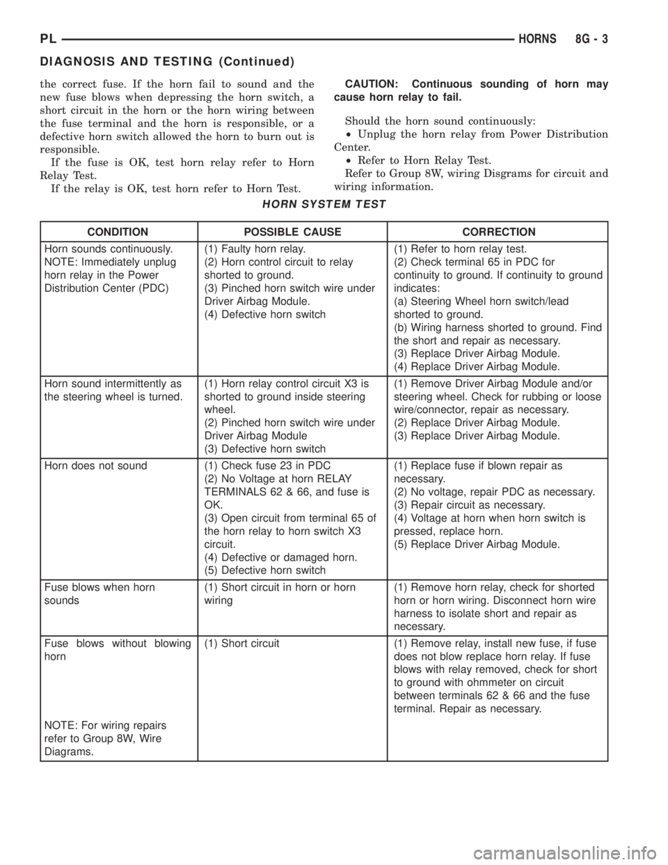
HORN SYSTEM TEST
CONDITION POSSIBLE CAUSE CORRECTION
Horn sounds continuously.
NOTE: Immediately unplug
horn relay in the Power
Distribution Center (PDC)(1) Faulty horn relay.
(2) Horn control circuit to relay
shorted to ground.
(3) Pinched horn switch wire under
Driver Airbag Module.
(4) Defective horn switch(1) Refer to horn relay test.
(2) Check terminal 65 in PDC for
continuity to ground. If continuity to ground
indicates:
(a) Steering Wheel horn switch/lead
shorted to ground.
(b) Wiring harness shorted to ground. Find
the short and repair as necessary.
(3) Replace Driver Airbag Module.
(4) Replace Driver Airbag Module.
Horn sound intermittently as
the steering wheel is turned.(1) Horn relay control circuit X3 is
shorted to ground inside steering
wheel.
(2) Pinched horn switch wire under
Driver Airbag Module
(3) Defective horn switch(1) Remove Driver Airbag Module and/or
steering wheel. Check for rubbing or loose
wire/connector, repair as necessary.
(2) Replace Driver Airbag Module.
(3) Replace Driver Airbag Module.
Horn does not sound (1) Check fuse 23 in PDC
(2) No Voltage at horn RELAY
TERMINALS 62 & 66, and fuse is
OK.
(3) Open circuit from terminal 65 of
the horn relay to horn switch X3
circuit.
(4) Defective or damaged horn.
(5) Defective horn switch(1) Replace fuse if blown repair as
necessary.
(2) No voltage, repair PDC as necessary.
(3) Repair circuit as necessary.
(4) Voltage at horn when horn switch is
pressed, replace horn.
(5) Replace Driver Airbag Module.
Fuse blows when horn
sounds(1) Short circuit in horn or horn
wiring(1) Remove horn relay, check for shorted
horn or horn wiring. Disconnect horn wire
harness to isolate short and repair as
necessary.
Fuse blows without blowing
horn(1) Short circuit (1) Remove relay, install new fuse, if fuse
does not blow replace horn relay. If fuse
blows with relay removed, check for short
to ground with ohmmeter on circuit
between terminals 62 & 66 and the fuse
terminal. Repair as necessary.
NOTE: For wiring repairs
refer to Group 8W, Wire
Diagrams.
PLHORNS 8G - 3
DIAGNOSIS AND TESTING (Continued)
Page 300 of 1200
The individual switches cannot be repaired. If one
switch fails, the entire switch module must be
replaced.
STOP LAMP SWITCH
Vehicles equipped with the speed control option use
a dual function stop lamp switch. The switch is
mounted on the brake pedal mounting bracket under
the instrument panel. The PCM monitors the state of
the dual function stop lamp switch. Refer to Group 5,
Brakes for more information on stop lamp switch ser-
vice and adjustment procedures.
SERVO CABLE
The speed control servo cable is connected between
the speed control vacuum servo diaphragm and the
throttle body control linkage. This cable causes the
throttle control linkage to open or close the throttle
valve in response to movement of the vacuum servo
diaphragm.
POWERTRAIN CONTROL MODULE
The speed control electronic control circuitry is
integrated into the Powertrain Control Module
(PCM). The PCM is located in the engine compart-
ment. The PCM speed control functions are moni-
tored by the On-Board Diagnostics (OBD). All OBD-
sensed systems are monitored by the PCM. Each
monitored circuit is assigned a Diagnostic Trouble
Code (DTC). The PCM will store a DTC in electronic
memory for any failure it detects. See On-Board
Diagnostic Tests in this group for more information.
The PCM cannot be repaired and must be replaced if
faulty.
USE THE DRB SCAN TOOL TO REPROGRAM
THE NEW PCM WITH THE VEHICLES ORIGI-
NAL IDENTIFICATION NUMBER (VIN) AND
THE ORIGINAL VEHICLES MILEAGE. IF THIS
STEP IS NOT DONE A DIAGNOSTIC TROUBLE
CODE (DTC) MAY BE SET.
VACUUM RESERVOIR
The reservoir contains a one-way check valve to
trap engine vacuum in the reservoir. When engine
vacuum drops, as in climbing a grade while driving,
the reservoir supplies the vacuum needed to main-
tain proper speed control operation. The vacuum res-
ervoir cannot be repaired and must be replaced if
faulty.
VEHICLE SPEED AND DISTANCE
The 4 speed automatic Transmission Control Mod-
ule (TCM) supplies the speed input to the PCM. The
PCM determines acceleration rates. The speed con-
trol software in the PCM uses vehicle speed and
acceleration to control to the set speed.Vehicles with a 3 speed automatic or manual trans-
mission have a vehicle speed sensor (VSS) mounted
to an adapter near the transmission output shaft.
The sensor is driven through the adapter by a speed-
ometer pinion gear. The VSS pulse signal is moni-
tored by the PCM to determine vehicle speed and to
maintain speed control set speed. Refer to the appro-
priate Powertrain Diagnostic Procedures manual for
diagnosis and testing of this component. Refer to
group 14, Fuel System for Removal/Installation
DIAGNOSIS AND TESTING
ROAD TEST
Perform a vehicle road test to verify reports of
speed control system malfunction. The road test
should include attention to the speedometer. Speed-
ometer operation should be smooth and without flut-
ter at all speeds.
Flutter in the speedometer indicates a problem
which might cause surging in the speed control sys-
tem. The cause of any speedometer problems should
be corrected before proceeding. Refer to Group 8E,
Instrument Panel and Gauges for speedometer diag-
nosis.
If a road test verifies a surge following a set and
the speedometer operates properly see ªOvershoot/
Undershoot on speed control setº.
If a road test verifies an inoperative system, and
the speedometer operates properly, check for:
²A Diagnostic Trouble Code (DTC). If a DTC
exists, conduct tests per the Powertrain Diagnostic
Procedures service manual.
²A misadjusted brake (stop) lamp switch. This
could also cause an intermittent problem.
²Loose or corroded electrical connections at the
servo. Corrosion should be removed from electrical
terminals and a light coating of Mopar Multipurpose
Grease, or equivalent, applied.
²Leaking vacuum reservoir.
²Loose or leaking vacuum hoses or connections.
²Defective one-way vacuum check valve.
²Secure attachment at both ends of the speed
control servo cable.
²Smooth operation of throttle linkage and throttle
body air valve.
²Conduct electrical test at PCM.
²Failed speed control servo. Do the servo vacuum
test.
CAUTION: When test probing for voltage or conti-
nuity at electrical connectors, care must be taken
not to damage connector, terminals or seals. If
these components are damaged, intermittent or
complete system failure may occur.
PLVEHICLE SPEED CONTROL SYSTEM 8H - 3
DESCRIPTION AND OPERATION (Continued)
Page 370 of 1200
POWER DOOR LOCKS
CONTENTS
page page
POWER DOOR LOCKS..................... 1REMOTE KEYLESS ENTRY.................. 3
POWER DOOR LOCKS
INDEX
page page
DESCRIPTION AND OPERATION
INTRODUCTION......................... 1
DIAGNOSIS AND TESTING
DOOR LOCK MOTOR..................... 1
DOOR LOCK SWITCH..................... 1WIRING................................ 1
REMOVAL AND INSTALLATION
DOOR LOCK MOTOR..................... 2
DOOR LOCK SWITCH..................... 2
DESCRIPTION AND OPERATION
INTRODUCTION
All doors can be locked or unlocked electrically by
operating the switch on either front door panels.
The rear doors can be locked or unlocked by actu-
ation of the front door switch, or can be locked or
unlocked mechanically and independently with their
respective locking knobs.
The front doors can be locked or unlocked mechan-
ically with the locking knob regardless of electrical
locking and unlocking actuation with the front door
knobs.
The right and left front door can be locked or
unlocked mechanically from the outside with the key
or electrically as described above.
CHILD PROTECTION LOCK
The child protection lock is on the rear door only.
The lock will disable the inside door handle from
opening the door when engaged. The lock is part of
the latch/lock assembly. The lock is engaged by mov-
ing a lever that is located on the rearward inside
edge of the door.
DIAGNOSIS AND TESTING
DOOR LOCK MOTOR
Make certain battery is in normal condition before
circuits are tested.To determine which motor is faulty, check each
individual door for electrical lock and unlock or dis-
connect the motor connectors one at a time, while
operating the door lock switch. In the event that
none of the motors work, the problem maybe caused
by a shorted motor, or a bad switch. Disconnecting
the defective motor will allow the others to work.
To test an individual door lock motor, disconnect
the electrical connector from the motor. To lock the
door, connect a 12 volt power source to the positive
pin of the lock motor and a ground wire to the other
pin (Fig. 1) To unlock the door reverse the wire con-
nections at the motor pin terminals. If these results
are NOT obtained, replace the door latch assembly.
DOOR LOCK SWITCH
Remove the switch from its mounting location.
Using an ohmmeter, refer to (Fig. 2) to determine if
continuity is correct in the Lock and Unlock switch
positions. If these results are not obtained, replace
the switch.
WIRING
The following wiring test sequence determines
whether or not voltage is continuous through the
body harness to switch.
(1) Remove left side switch from door trim panel.
(2) Carefully separate multiple terminal block on
wiring harness from switch body.
PLPOWER DOOR LOCKS 8P - 1
Page 376 of 1200
IMMOBILIZER SYSTEM
CONTENTS
page page
DESCRIPTION AND OPERATION
IMMOBILIZER RECEIVER................ 1
IMMOBILIZER SYSTEM.................. 1
IMMOBILIZER TRANSMITTER............. 2
POWER-UP MODE...................... 2
DIAGNOSIS AND TESTING
IMMOBILIZER DIAGNOSIS............... 2SERVICE PROCEDURES
VEHICLE IMMOBILIZER SYSTEM.......... 3
REMOVAL AND INSTALLATION
IMMOBILIZER RECEIVER................ 3
DESCRIPTION AND OPERATION
IMMOBILIZER SYSTEM
The Immobilizer system includes the following
unique items:
²An immobilizer module receiver that controls
system operation and also controls the RKE and Illu-
minated entry systems, if equipped.
²An encoded Crankshaft Position Sensor for the
ignition system. The Immobilizer module decodes the
signal from the crankshaft so the PCM can recognize
it as a valid Crankshaft Position Sensor signal, and
allow the engine to run.
²A wiring harness that interconnects the crank-
shaft sensor, the immobilizer receiver, and the PCM.
²Two key fob transmitters.
The Immobilizer System prevents unauthorized
operation of the vehicle by disabling the engine and
starter. The system will NOT allow the vehicle to
start unless the UNLOCK button on the RKE trans-
mitter is pressed. The system will be activated after
turning the ignition switch to the OFF position and
using one of the following methods.
(1) Press the LOCK button on the RKE transmit-
ter.
(2) LOCK the doors by pressing a power lock but-
ton switch.
(3) LOCK the driver or passenger door using the
key.
²The Security light will flash, for about 16 sec-
onds, indicating that the engine and starter will be
disabled.
²The Security light remaining on, indicates the
system is not operational.
²The Immobilizer will activate automatically
within 10 minutes of the ignition switch being in the
OFF position, whether the vehicle has been locked or
unlocked.²An attempt to start the vehicle without pressing
the UNLOCK button on the RKE transmitter will
result in a warning chime and the Security light
flashing.
NOTE: The ignition switch must be in the OFF posi-
tion in order for the system to be activated, whether
the doors are closed or not.
IMMOBILIZER RECEIVER
The immobilizer receiver is programmed to
respond to the Lock and Unlock radio signals issued
by the immobilizer transmitters. The receiver will
only respond to the radio signals of transmitters (up
to four) whose vehicle access codes have been stored
in the receiver's electronic memory. The receiver is
programmed at the assembly plant with the vehicle
access codes of the two transmitters that are shipped
with the vehicle.
The immobilizer receiver also has a central pro-
cessing unit, which contains the immobilizer system
logic. The programming in the immobilizer receiver
allows the system to learn and retain transmitter
vehicle access codes, as well as to communicate with
the Powertrain Control Module (PCM) and/or the
DRB scan tool on the Chrysler Collision Detection
(CCD) data bus network.
The CCD data bus network allows the sharing of
sensor information. This helps to reduce wiring har-
ness complexity, reduce internal controller hardware,
and reduce component sensor current loads. At the
same time, the CCD data bus network provides
increased reliability and enhanced diagnostic capabil-
ities.
Each immobilizer transmitter has a different vehi-
cle access code, which must be programmed into the
memory of the immobilizer receiver in the vehicle in
order to operate the immobilizer system. A DRB scan
tool must be used to program new or additional
PLIMMOBILIZER SYSTEM 8Q - 1
Page 385 of 1200
MIRROR MOTOR
(1) Remove door trim panel, refer to Group 23
Front Door Trim.
(2) Remove switch mounting screws from back side
of trim panel and remove switch.
(3) Disconnect wire connector.
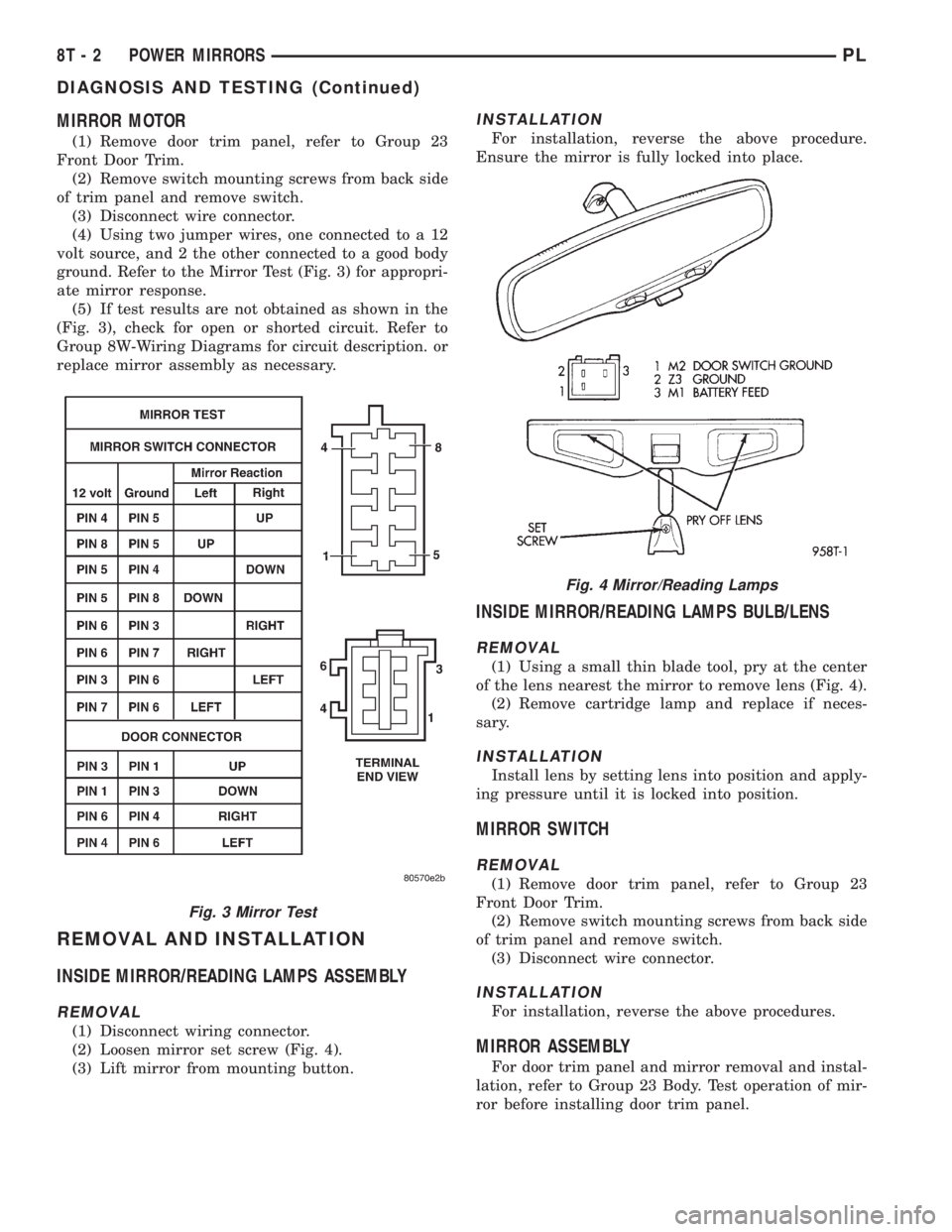
(4) Using two jumper wires, one connected to a 12
volt source, and 2 the other connected to a good body
ground. Refer to the Mirror Test (Fig. 3) for appropri-
ate mirror response.
(5) If test results are not obtained as shown in the
(Fig. 3), check for open or shorted circuit. Refer to
Group 8W-Wiring Diagrams for circuit description. or
replace mirror assembly as necessary.
REMOVAL AND INSTALLATION
INSIDE MIRROR/READING LAMPS ASSEMBLY
REMOVAL
(1) Disconnect wiring connector.
(2) Loosen mirror set screw (Fig. 4).
(3) Lift mirror from mounting button.
INSTALLATION
For installation, reverse the above procedure.
Ensure the mirror is fully locked into place.
INSIDE MIRROR/READING LAMPS BULB/LENS
REMOVAL
(1) Using a small thin blade tool, pry at the center
of the lens nearest the mirror to remove lens (Fig. 4).
(2) Remove cartridge lamp and replace if neces-
sary.
INSTALLATION
Install lens by setting lens into position and apply-
ing pressure until it is locked into position.
MIRROR SWITCH
REMOVAL
(1) Remove door trim panel, refer to Group 23
Front Door Trim.
(2) Remove switch mounting screws from back side
of trim panel and remove switch.
(3) Disconnect wire connector.
INSTALLATION
For installation, reverse the above procedures.
MIRROR ASSEMBLY
For door trim panel and mirror removal and instal-
lation, refer to Group 23 Body. Test operation of mir-
ror before installing door trim panel.
Fig. 3 Mirror Test
Fig. 4 Mirror/Reading Lamps
8T - 2 POWER MIRRORSPL
DIAGNOSIS AND TESTING (Continued)
Page 387 of 1200
MIRROR MOTOR
(1) Remove door trim panel, refer to Group 23
Front Door Trim.
(2) Remove switch mounting screws from back side
of trim panel and remove switch.
(3) Disconnect wire connector.
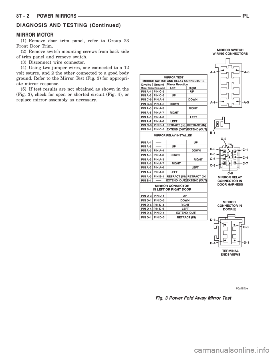
(4) Using two jumper wires, one connected to a 12
volt source, and 2 the other connected to a good body
ground. Refer to the Mirror Test (Fig. 3) for appropri-
ate mirror response.
(5) If test results are not obtained as shown in the
(Fig. 3), check for open or shorted circuit (Fig. 4), or
replace mirror assembly as necessary.
Fig. 3 Power Fold Away Mirror Test
8T - 2 POWER MIRRORSPL
DIAGNOSIS AND TESTING (Continued)
Page 401 of 1200
WARNING: BE SURE THAT THE IGNITION SWITCH
ALWAYS IS IN THE OFF POSITION, UNLESS THE
PROCEDURE REQUIRES IT TO BE ON.
WARNING: SET THE PARKING BRAKE WHEN
WORKING ON ANY VEHICLE. AN AUTOMATIC
TRANSMISSION SHOULD BE IN PARK. A MANUAL
TRANSMISSION SHOULD BE IN NEUTRAL.
WARNING: OPERATE THE ENGINE ONLY IN A
WELL-VENTILATED AREA.
WARNING: KEEP AWAY FROM MOVING PARTS
WHEN THE ENGINE IS RUNNING, ESPECIALLY THE
FAN AND BELTS.
WARNING: TO PREVENT SERIOUS BURNS, AVOID
CONTACT WITH HOT PARTS SUCH AS THE RADIA-
TOR, EXHAUST MANIFOLD(S), TAIL PIPE, CATA-
LYTIC CONVERTER, AND MUFFLER.
WARNING: DO NOT ALLOW FLAME OR SPARKS
NEAR THE BATTERY. GASES ARE ALWAYS
PRESENT IN AND AROUND THE BATTERY.
WARNING: ALWAYS REMOVE RINGS, WATCHES,
LOOSE HANGING JEWELRY, AND LOOSE CLOTH-
ING.
TAKE OUTS
The abbreviation T/O is used in the component
location section to indicate a point in which the wir-
ing harness branches out to a component.
ELECTROSTATIC DISCHARGE (ESD) SENSITIVE
DEVICES
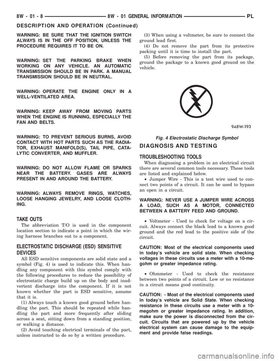
All ESD sensitive components are solid state and a
symbol (Fig. 4) is used to indicate this. When han-
dling any component with this symbol comply with
the following procedures to reduce the possibility of
electrostatic charge build up on the body and inad-
vertent discharge into the component. If it is not
known whether the part is ESD sensitive, assume
that it is.
(1) Always touch a known good ground before han-
dling the part. This should be repeated while han-
dling the part and more frequently after sliding
across a seat, sitting down from a standing position,
or walking a distance.
(2) Avoid touching electrical terminals of the part,
unless instructed to do so by a written procedure.(3) When using a voltmeter, be sure to connect the
ground lead first.
(4) Do not remove the part from its protective
packing until it is time to install the part.
(5) Before removing the part from its package,
ground the package to a known good ground on the
vehicle.
DIAGNOSIS AND TESTING
TROUBLESHOOTING TOOLS
When diagnosing a problem in an electrical circuit
there are several common tools necessary. These tools
are listed and explained below.
²Jumper Wire - This is a test wire used to con-
nect two points of a circuit. It can be used to bypass
an open in a circuit.
WARNING: NEVER USE A JUMPER WIRE ACROSS
A LOAD, SUCH AS A MOTOR, CONNECTED
BETWEEN A BATTERY FEED AND GROUND.
²Voltmeter - Used to check for voltage on a cir-
cuit. Always connect the black lead to a known good
ground and the red lead to the positive side of the
circuit.
CAUTION: Most of the electrical components used
in today's vehicle are solid state. When checking
voltages in these circuits use a meter with a 10-me-
gohm or greater impedance rating.
²Ohmmeter - Used to check the resistance
between two points of a circuit. Low or no resistance
in a circuit means good continuity.
CAUTION: - Most of the electrical components used
in today's vehicle are Solid State. When checking
resistance in these circuits use a meter with a 10-
megohm or greater impedance rating. In addition,
make sure the power is disconnected from the cir-
cuit. Circuits that are powered up by the vehicle
electrical system can cause damage to the equip-
ment and provide false readings.
Fig. 4 Electrostatic Discharge Symbol
8W - 01 - 8 8W - 01 GENERAL INFORMATIONPL
DESCRIPTION AND OPERATION (Continued)