1999 DODGE NEON warning
[x] Cancel search: warningPage 357 of 1200
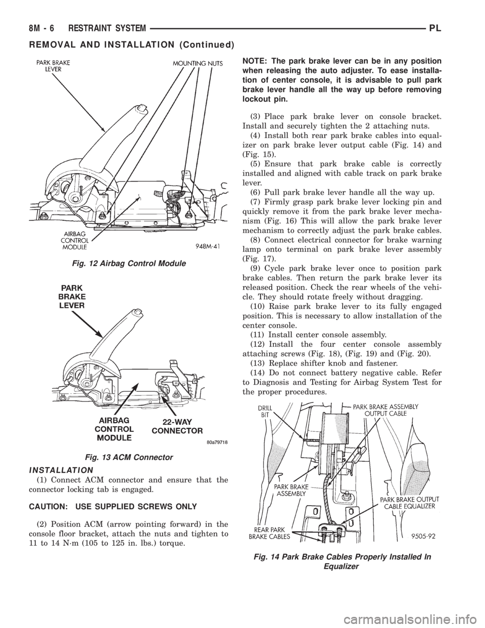
INSTALLATION
(1) Connect ACM connector and ensure that the
connector locking tab is engaged.
CAUTION: USE SUPPLIED SCREWS ONLY
(2) Position ACM (arrow pointing forward) in the
console floor bracket, attach the nuts and tighten to
11 to 14 N´m (105 to 125 in. lbs.) torque.NOTE: The park brake lever can be in any position
when releasing the auto adjuster. To ease installa-
tion of center console, it is advisable to pull park
brake lever handle all the way up before removing
lockout pin.
(3) Place park brake lever on console bracket.
Install and securely tighten the 2 attaching nuts.
(4) Install both rear park brake cables into equal-
izer on park brake lever output cable (Fig. 14) and
(Fig. 15).
(5) Ensure that park brake cable is correctly
installed and aligned with cable track on park brake
lever.
(6) Pull park brake lever handle all the way up.
(7) Firmly grasp park brake lever locking pin and
quickly remove it from the park brake lever mecha-
nism (Fig. 16) This will allow the park brake lever
mechanism to correctly adjust the park brake cables.
(8) Connect electrical connector for brake warning
lamp onto terminal on park brake lever assembly
(Fig. 17).
(9) Cycle park brake lever once to position park
brake cables. Then return the park brake lever its
released position. Check the rear wheels of the vehi-
cle. They should rotate freely without dragging.
(10) Raise park brake lever to its fully engaged
position. This is necessary to allow installation of the
center console.
(11) Install center console assembly.
(12) Install the four center console assembly
attaching screws (Fig. 18), (Fig. 19) and (Fig. 20).
(13) Replace shifter knob and fastener.
(14) Do not connect battery negative cable. Refer
to Diagnosis and Testing for Airbag System Test for
the proper procedures.
Fig. 12 Airbag Control Module
Fig. 13 ACM Connector
Fig. 14 Park Brake Cables Properly Installed In
Equalizer
8M - 6 RESTRAINT SYSTEMPL
REMOVAL AND INSTALLATION (Continued)
Page 358 of 1200
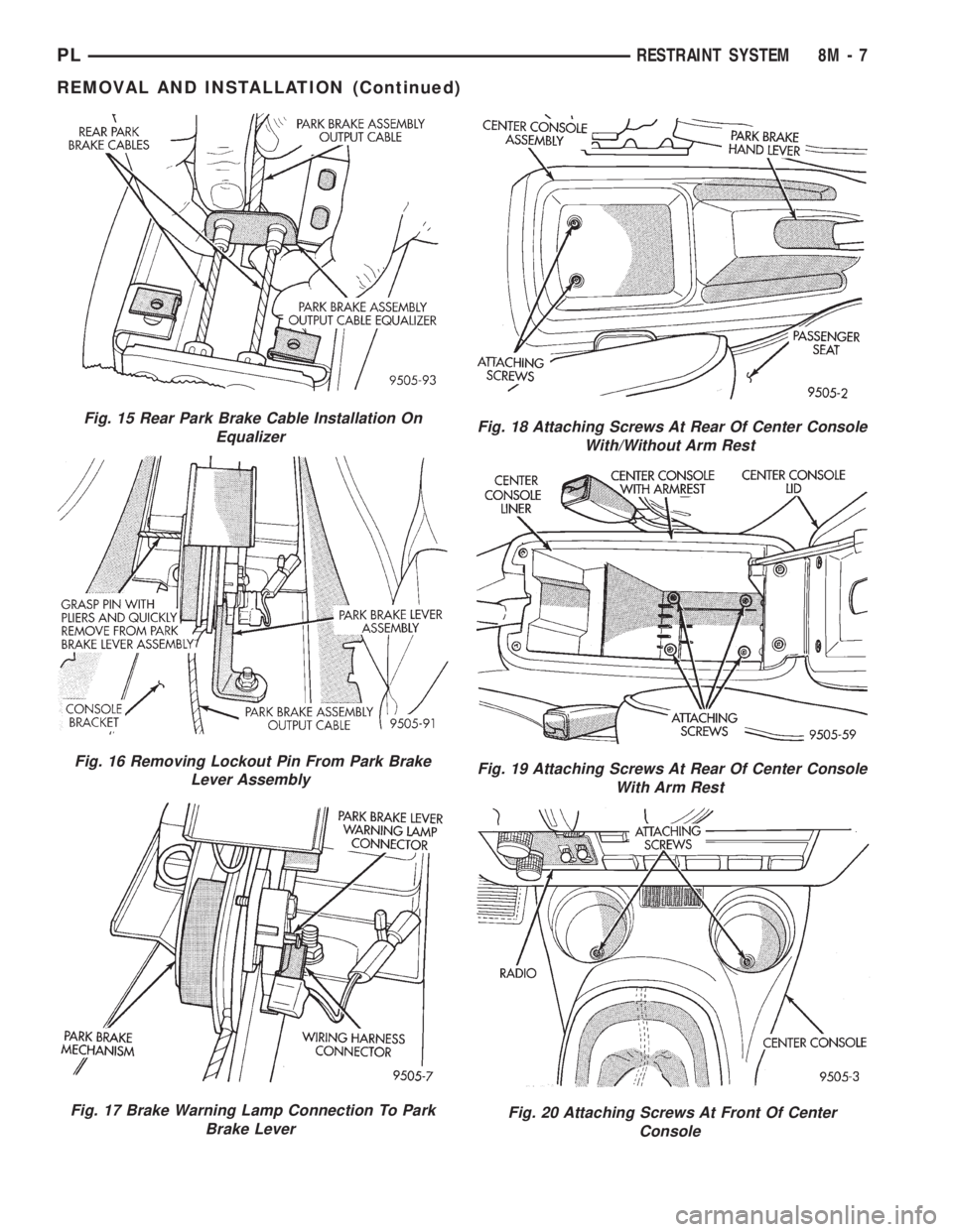
Fig. 15 Rear Park Brake Cable Installation On
Equalizer
Fig. 16 Removing Lockout Pin From Park Brake
Lever Assembly
Fig. 17 Brake Warning Lamp Connection To Park
Brake Lever
Fig. 18 Attaching Screws At Rear Of Center Console
With/Without Arm Rest
Fig. 19 Attaching Screws At Rear Of Center Console
With Arm Rest
Fig. 20 Attaching Screws At Front Of Center
Console
PLRESTRAINT SYSTEM 8M - 7
REMOVAL AND INSTALLATION (Continued)
Page 359 of 1200
CLOCKSPRING
REMOVAL
WARNING: DISCONNECT AND ISOLATE THE BAT-
TERY NEGATIVE (GROUND) CABLE BEFORE
BEGINNING ANY AIRBAG SYSTEM COMPONENT
REMOVAL OR INSTALLATION PROCEDURE. THIS
WILL DISABLE THE AIRBAG SYSTEM. FAILURE TO
DISCONNECT BATTERY COULD RESULT IN ACCI-
DENTAL AIRBAG DEPLOYMENT AND POSSIBLE
PERSONAL INJURY. ALLOW SYSTEM CAPACITOR
TO DISCHARGE FOR 2 MINUTES BEFORE REMOV-
ING ANY AIRBAG COMPONENTS.
(1) Place the front road wheels in the straight
ahead position then:
²Rotate the steering wheel half turn (180
degrees) to the right (clockwise)
²Lock column with ignition lock cylinder.
(2) Disconnect and isolate the battery negative
cable.
(3) Wait two minutes for the reserve capacitor to
discharge before removing non-deployed module.
(4) Remove speed control switch mounting screws,
switches and disconnect the wire connectors or
remove covers.
(5) Remove the Driver Airbag Module attaching
bolts from under the speed control switches or covers.
(6) Lift module and disconnect the airbag and horn
wire connectors.
(7) Remove the steering wheel, refer to Steering
Wheel removal procedures.
(8) Remove upper and lower steering column
shrouds to gain access to clockspring wiring.
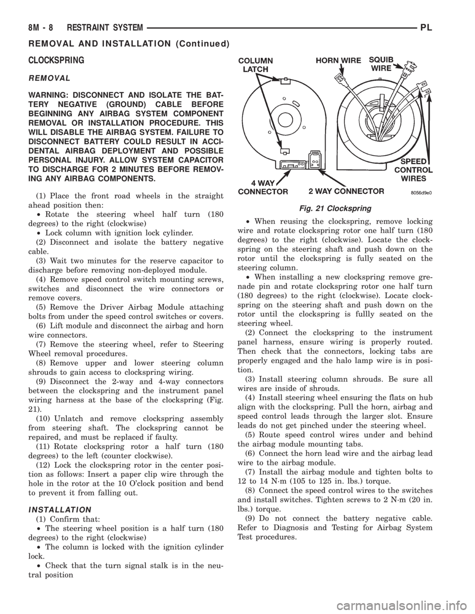
(9) Disconnect the 2-way and 4-way connectors
between the clockspring and the instrument panel
wiring harness at the base of the clockspring (Fig.
21).
(10) Unlatch and remove clockspring assembly
from steering shaft. The clockspring cannot be
repaired, and must be replaced if faulty.
(11) Rotate clockspring rotor a half turn (180
degrees) to the left (counter clockwise).
(12) Lock the clockspring rotor in the center posi-
tion as follows: Insert a paper clip wire through the
hole in the rotor at the 10 O'clock position and bend
to prevent it from falling out.
INSTALLATION
(1) Confirm that:
²The steering wheel position is a half turn (180
degrees) to the right (clockwise)
²The column is locked with the ignition cylinder
lock.
²Check that the turn signal stalk is in the neu-
tral position²When reusing the clockspring, remove locking
wire and rotate clockspring rotor one half turn (180
degrees) to the right (clockwise). Locate the clock-
spring on the steering shaft and push down on the
rotor until the clockspring is fully seated on the
steering column.
²When installing a new clockspring remove gre-
nade pin and rotate clockspring rotor one half turn
(180 degrees) to the right (clockwise). Locate clock-
spring on the steering shaft and push down on the
rotor until the clockspring is fullly seated on the
steering wheel.
(2) Connect the clockspring to the instrument
panel harness, ensure wiring is properly routed.
Then check that the connectors, locking tabs are
properly engaged and the halo lamp wire is in posi-
tion.
(3) Install steering column shrouds. Be sure all
wires are inside of shrouds.
(4) Install steering wheel ensuring the flats on hub
align with the clockspring. Pull the horn, airbag and
speed control leads through the larger slot. Ensure
leads do not get pinched under the steering wheel.
(5) Route speed control wires under and behind
the airbag module mounting tabs.
(6) Connect the horn lead wire and the airbag lead
wire to the airbag module.
(7) Install the airbag module and tighten bolts to
12 to 14 N´m (105 to 125 in. lbs.) torque.
(8) Connect the speed control wires to the switches
and install switches. Tighten screws to 2 N´m (20 in.
lbs.) torque.
(9) Do not connect the battery negative cable.
Refer to Diagnosis and Testing for Airbag System
Test procedures.
Fig. 21 Clockspring
8M - 8 RESTRAINT SYSTEMPL
REMOVAL AND INSTALLATION (Continued)
Page 360 of 1200
DRIVER AIRBAG MODULE
REMOVAL
WARNING: DISCONNECT AND ISOLATE THE BAT-
TERY NEGATIVE (GROUND) CABLE BEFORE
BEGINNING ANY AIRBAG SYSTEM COMPONENT
REMOVAL OR INSTALLATION PROCEDURE. THIS
WILL DISABLE THE AIRBAG SYSTEM. FAILURE TO
DISCONNECT BATTERY COULD RESULT IN ACCI-
DENTAL AIRBAG DEPLOYMENT AND POSSIBLE
PERSONAL INJURY. ALLOW SYSTEM CAPACITOR
TO DISCHARGE FOR 2 MINUTES BEFORE REMOV-
ING ANY AIRBAG COMPONENTS.
When removing a deployed module, rubber gloves,
eye protection and long sleeved shirt should be worn,
as there may be deposits on the surface which could
irritate the skin and eyes.
(1) Disconnect and isolate the battery negative
cable.
(2) Remove speed control switches or covers from
steering wheel armature and disconnect the wires.
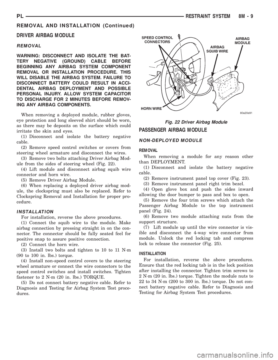
(3) Remove two bolts attaching Driver Airbag Mod-
ule from the sides of steering wheel (Fig. 22).
(4) Lift module and disconnect airbag squib wire
connector and horn wire.
(5) Remove Driver Airbag Module.
(6) When replacing a deployed driver airbag mod-
ule, the clockspring must also be replaced. Refer to
Clockspring Removal and Installation for proper pro-
cedure.
INSTALLATION
For installation, reverse the above procedures.
(1) Connect the squib wire to the module. Make
airbag connection by pressing straight in on the con-
nector. The connector should be fully seated feel for
positive snap to assure positive connection.
(2) Connect the horn wire.
(3) Install two bolts and tighten to 10 to 11 N´m
(90 to 100 in. lbs.) torque.
(4) Install non-speed control covers to the steering
wheel armature or connect the wire connectors to the
speed control switches and install switches. Tighten
fastener to 2 N´m (20 in. lbs.) TORQUE.
(5) Do not connect battery negative cable. Refer to
Diagnosis and Testing for Airbag System Test proce-
dures.
PASSENGER AIRBAG MODULE
NON-DEPLOYED MODULE
REMOVAL
When removing a module for any reason other
than DEPLOYMENT.
(1) Disconnect and isolate the battery negative
cable.
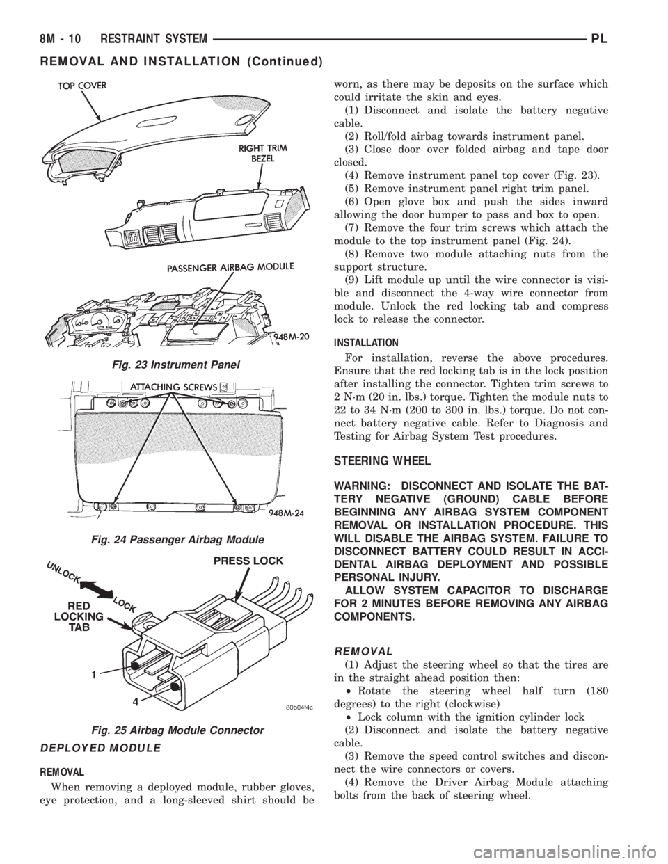
(2) Remove instrument panel top cover (Fig. 23).
(3) Remove instrument panel right trim bezel.
(4) Open glove box and push the sides inward
allowing the door bumper to pass and box to open.
(5) Remove the four trim screws which attach the
Passenger Airbag Module to the top instrument
panel (Fig. 24).
(6) Remove two module attaching nuts from the
support structure.
(7) Lift module up until the wire connector is vis-
ible and disconnect the 4-way wire connector from
module. Unlock the red locking tab and compress
lock to release the connector (Fig. 25).
INSTALLATION
For installation, reverse the above procedures.
Ensure that the red locking tab is in the lock position
after installing the connector. Tighten trim screws to
2 N´m (20 in. lbs.) torque. Tighten the module nuts to
22 to 34 N´m (200 to 300 in. lbs.) torque. Do not con-
nect battery negative cable. Refer to Diagnosis and
Testing for Airbag System Test procedures.
Fig. 22 Driver Airbag Module
PLRESTRAINT SYSTEM 8M - 9
REMOVAL AND INSTALLATION (Continued)
Page 361 of 1200
DEPLOYED MODULE
REMOVAL
When removing a deployed module, rubber gloves,
eye protection, and a long-sleeved shirt should beworn, as there may be deposits on the surface which
could irritate the skin and eyes.
(1) Disconnect and isolate the battery negative
cable.
(2) Roll/fold airbag towards instrument panel.
(3) Close door over folded airbag and tape door
closed.
(4) Remove instrument panel top cover (Fig. 23).
(5) Remove instrument panel right trim panel.
(6) Open glove box and push the sides inward
allowing the door bumper to pass and box to open.
(7) Remove the four trim screws which attach the
module to the top instrument panel (Fig. 24).
(8) Remove two module attaching nuts from the
support structure.
(9) Lift module up until the wire connector is visi-
ble and disconnect the 4-way wire connector from
module. Unlock the red locking tab and compress
lock to release the connector.
INSTALLATION
For installation, reverse the above procedures.
Ensure that the red locking tab is in the lock position
after installing the connector. Tighten trim screws to
2 N´m (20 in. lbs.) torque. Tighten the module nuts to
22 to 34 N´m (200 to 300 in. lbs.) torque. Do not con-
nect battery negative cable. Refer to Diagnosis and
Testing for Airbag System Test procedures.
STEERING WHEEL
WARNING: DISCONNECT AND ISOLATE THE BAT-
TERY NEGATIVE (GROUND) CABLE BEFORE
BEGINNING ANY AIRBAG SYSTEM COMPONENT
REMOVAL OR INSTALLATION PROCEDURE. THIS
WILL DISABLE THE AIRBAG SYSTEM. FAILURE TO
DISCONNECT BATTERY COULD RESULT IN ACCI-
DENTAL AIRBAG DEPLOYMENT AND POSSIBLE
PERSONAL INJURY.
ALLOW SYSTEM CAPACITOR TO DISCHARGE
FOR 2 MINUTES BEFORE REMOVING ANY AIRBAG
COMPONENTS.
REMOVAL
(1) Adjust the steering wheel so that the tires are
in the straight ahead position then:
²Rotate the steering wheel half turn (180
degrees) to the right (clockwise)
²Lock column with the ignition cylinder lock
(2) Disconnect and isolate the battery negative
cable.
(3) Remove the speed control switches and discon-
nect the wire connectors or covers.
(4) Remove the Driver Airbag Module attaching
bolts from the back of steering wheel.
Fig. 23 Instrument Panel
Fig. 24 Passenger Airbag Module
Fig. 25 Airbag Module Connector
8M - 10 RESTRAINT SYSTEMPL
REMOVAL AND INSTALLATION (Continued)
Page 362 of 1200
(5) Lift module and disconnect the airbag and horn
wire connectors.
(6) Remove steering wheel retaining nut.
(7) Remove the steering wheel with a steering
wheel puller. While removing the steering wheel take
care to feed the wires gently through the holes in the
clockspring armature.
INSTALLATION
(1) Confirm that:
²The steering wheel position is a half turn (180
degrees) to the right (clockwise)
²The column is locked with the ignition cylinder
lock.
²Check that the turn signal stalk is in the neu-
tral position
(2) Install the steering wheel ensuring the flats on
hub align with the clockspring. Pull the horn lead,
airbag and speed control leads through the larger
slot. Ensure leads do not get pinched under the steer-
ing wheel.
(3) Install the steering wheel retaining nut, and
tighten it to 61 N´m (45 ft. lbs.) torque.
(4) Install the airbag module. Refer to Driver Air-
bag Module Removal and Installation for proper pro-
cedures.
(5) Do not connect the battery negative cable.
Refer to Diagnosis and Testing for Airbag System
Test procedures.
ADJUSTMENTS
CLOCKSPRING CENTERING PROCEDURE
If the rotating tape within the clockspring is not
positioned properly with the steering wheel and the
front wheels, the clockspring may fail during use.
The following procedure MUST BE USED to center
the clockspring if:²The clockspring is not known to be properly
positioned
²The front wheels were moved
²The steering wheel was moved from the half
turn (180 degrees) to the right (clockwise) position.
WARNING: DISCONNECT AND ISOLATE THE BAT-
TERY NEGATIVE (GROUND) CABLE BEFORE
BEGINNING ANY AIRBAG SYSTEM COMPONENT
REMOVAL OR INSTALLATION PROCEDURE. THIS
WILL DISABLE THE AIRBAG SYSTEM. FAILURE TO
DISCONNECT BATTERY COULD RESULT IN ACCI-
DENTAL AIRBAG DEPLOYMENT AND POSSIBLE
PERSONAL INJURY.
ALLOW SYSTEM CAPACITOR TO DISCHARGE
FOR 2 MINUTES BEFORE REMOVING ANY AIRBAG
COMPONENTS.
(1) Remove clockspring, refer to Clockspring
Removal.
(2) Rotate the clockspring rotor in the CLOCK-
WISE DIRECTION to the end of travel. Do not apply
excessive torque.
(3) From the end of travel, rotate the rotor two full
turns and a half in the counterclockwise direction.
The horn wire and the squib wire should end up at
the bottom. If not, rotate the rotor counter clockwise
until the wires are properly orientated, but not more
than half turn (180 degrees). Engage clockspring
locking mechanism.
(4) For installation, refer to Clockspring Installa-
tion
(5) Do not connect battery negative cable. Refer to
Diagnosis and Testing for Airbag System Test
procedures.
PLRESTRAINT SYSTEM 8M - 11
REMOVAL AND INSTALLATION (Continued)
Page 366 of 1200
Instrument Panel and Systems for removal proce-
dures.
(2) Turn the ignition switch ON.
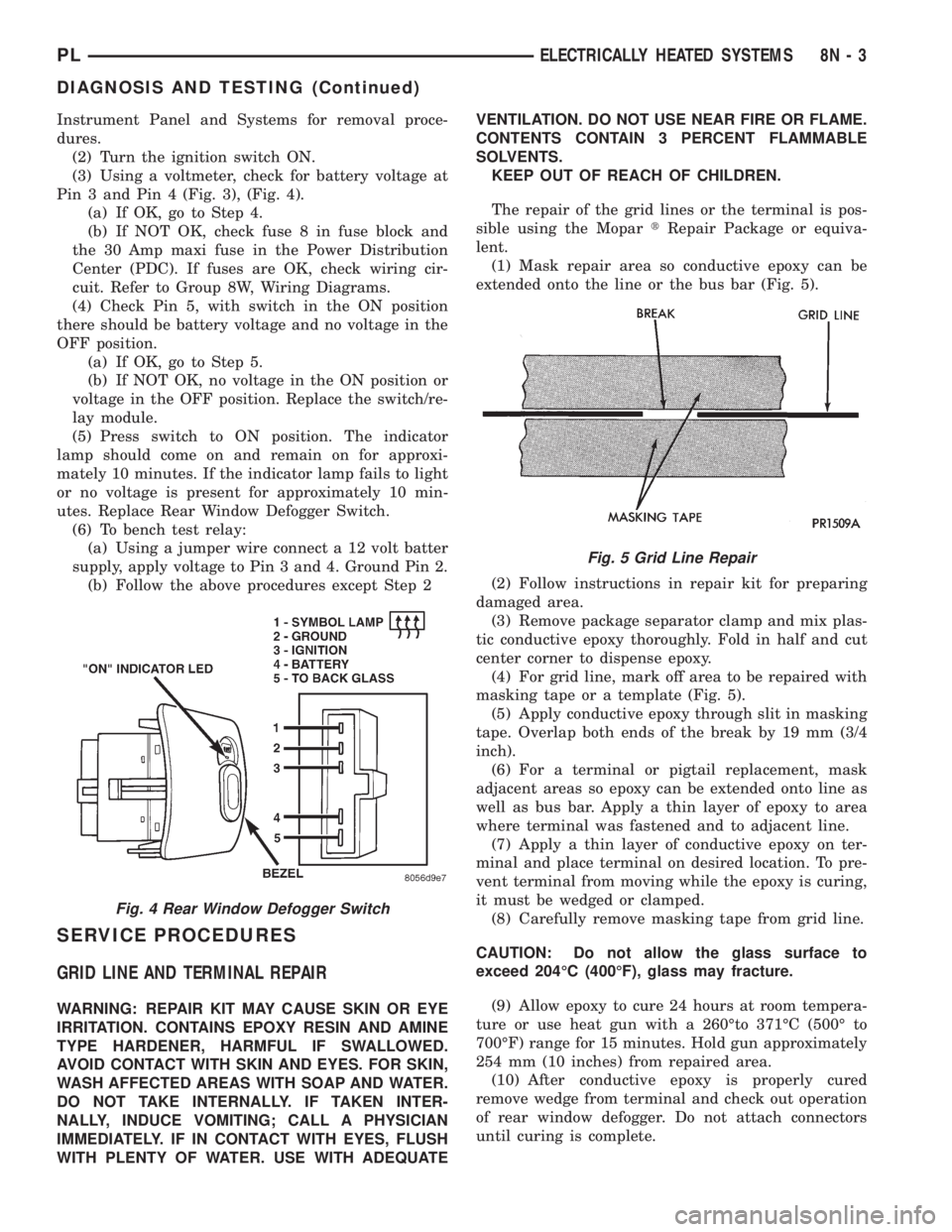
(3) Using a voltmeter, check for battery voltage at
Pin 3 and Pin 4 (Fig. 3), (Fig. 4).
(a) If OK, go to Step 4.
(b) If NOT OK, check fuse 8 in fuse block and
the 30 Amp maxi fuse in the Power Distribution
Center (PDC). If fuses are OK, check wiring cir-
cuit. Refer to Group 8W, Wiring Diagrams.
(4) Check Pin 5, with switch in the ON position
there should be battery voltage and no voltage in the
OFF position.
(a) If OK, go to Step 5.
(b) If NOT OK, no voltage in the ON position or
voltage in the OFF position. Replace the switch/re-
lay module.
(5) Press switch to ON position. The indicator
lamp should come on and remain on for approxi-
mately 10 minutes. If the indicator lamp fails to light
or no voltage is present for approximately 10 min-
utes. Replace Rear Window Defogger Switch.
(6) To bench test relay:
(a) Using a jumper wire connect a 12 volt batter
supply, apply voltage to Pin 3 and 4. Ground Pin 2.
(b) Follow the above procedures except Step 2
SERVICE PROCEDURES
GRID LINE AND TERMINAL REPAIR
WARNING: REPAIR KIT MAY CAUSE SKIN OR EYE
IRRITATION. CONTAINS EPOXY RESIN AND AMINE
TYPE HARDENER, HARMFUL IF SWALLOWED.
AVOID CONTACT WITH SKIN AND EYES. FOR SKIN,
WASH AFFECTED AREAS WITH SOAP AND WATER.
DO NOT TAKE INTERNALLY. IF TAKEN INTER-
NALLY, INDUCE VOMITING; CALL A PHYSICIAN
IMMEDIATELY. IF IN CONTACT WITH EYES, FLUSH
WITH PLENTY OF WATER. USE WITH ADEQUATEVENTILATION. DO NOT USE NEAR FIRE OR FLAME.
CONTENTS CONTAIN 3 PERCENT FLAMMABLE
SOLVENTS.
KEEP OUT OF REACH OF CHILDREN.
The repair of the grid lines or the terminal is pos-
sible using the MopartRepair Package or equiva-
lent.
(1) Mask repair area so conductive epoxy can be
extended onto the line or the bus bar (Fig. 5).
(2) Follow instructions in repair kit for preparing
damaged area.
(3) Remove package separator clamp and mix plas-
tic conductive epoxy thoroughly. Fold in half and cut
center corner to dispense epoxy.
(4) For grid line, mark off area to be repaired with
masking tape or a template (Fig. 5).
(5) Apply conductive epoxy through slit in masking
tape. Overlap both ends of the break by 19 mm (3/4
inch).
(6) For a terminal or pigtail replacement, mask
adjacent areas so epoxy can be extended onto line as
well as bus bar. Apply a thin layer of epoxy to area
where terminal was fastened and to adjacent line.
(7) Apply a thin layer of conductive epoxy on ter-
minal and place terminal on desired location. To pre-
vent terminal from moving while the epoxy is curing,
it must be wedged or clamped.
(8) Carefully remove masking tape from grid line.
CAUTION: Do not allow the glass surface to
exceed 204ÉC (400ÉF), glass may fracture.
(9) Allow epoxy to cure 24 hours at room tempera-
ture or use heat gun with a 260Éto 371ÉC (500É to
700ÉF) range for 15 minutes. Hold gun approximately
254 mm (10 inches) from repaired area.
(10) After conductive epoxy is properly cured
remove wedge from terminal and check out operation
of rear window defogger. Do not attach connectors
until curing is complete.
Fig. 4 Rear Window Defogger Switch
Fig. 5 Grid Line Repair
PLELECTRICALLY HEATED SYSTEMS 8N - 3
DIAGNOSIS AND TESTING (Continued)
Page 376 of 1200
IMMOBILIZER SYSTEM
CONTENTS
page page
DESCRIPTION AND OPERATION
IMMOBILIZER RECEIVER................ 1
IMMOBILIZER SYSTEM.................. 1
IMMOBILIZER TRANSMITTER............. 2
POWER-UP MODE...................... 2
DIAGNOSIS AND TESTING
IMMOBILIZER DIAGNOSIS............... 2SERVICE PROCEDURES
VEHICLE IMMOBILIZER SYSTEM.......... 3
REMOVAL AND INSTALLATION
IMMOBILIZER RECEIVER................ 3
DESCRIPTION AND OPERATION
IMMOBILIZER SYSTEM
The Immobilizer system includes the following
unique items:
²An immobilizer module receiver that controls
system operation and also controls the RKE and Illu-
minated entry systems, if equipped.
²An encoded Crankshaft Position Sensor for the
ignition system. The Immobilizer module decodes the
signal from the crankshaft so the PCM can recognize
it as a valid Crankshaft Position Sensor signal, and
allow the engine to run.
²A wiring harness that interconnects the crank-
shaft sensor, the immobilizer receiver, and the PCM.
²Two key fob transmitters.
The Immobilizer System prevents unauthorized
operation of the vehicle by disabling the engine and
starter. The system will NOT allow the vehicle to
start unless the UNLOCK button on the RKE trans-
mitter is pressed. The system will be activated after
turning the ignition switch to the OFF position and
using one of the following methods.
(1) Press the LOCK button on the RKE transmit-
ter.
(2) LOCK the doors by pressing a power lock but-
ton switch.
(3) LOCK the driver or passenger door using the
key.
²The Security light will flash, for about 16 sec-
onds, indicating that the engine and starter will be
disabled.
²The Security light remaining on, indicates the
system is not operational.
²The Immobilizer will activate automatically
within 10 minutes of the ignition switch being in the
OFF position, whether the vehicle has been locked or
unlocked.²An attempt to start the vehicle without pressing
the UNLOCK button on the RKE transmitter will
result in a warning chime and the Security light
flashing.
NOTE: The ignition switch must be in the OFF posi-
tion in order for the system to be activated, whether
the doors are closed or not.
IMMOBILIZER RECEIVER
The immobilizer receiver is programmed to
respond to the Lock and Unlock radio signals issued
by the immobilizer transmitters. The receiver will
only respond to the radio signals of transmitters (up
to four) whose vehicle access codes have been stored
in the receiver's electronic memory. The receiver is
programmed at the assembly plant with the vehicle
access codes of the two transmitters that are shipped
with the vehicle.
The immobilizer receiver also has a central pro-
cessing unit, which contains the immobilizer system
logic. The programming in the immobilizer receiver
allows the system to learn and retain transmitter
vehicle access codes, as well as to communicate with
the Powertrain Control Module (PCM) and/or the
DRB scan tool on the Chrysler Collision Detection
(CCD) data bus network.
The CCD data bus network allows the sharing of
sensor information. This helps to reduce wiring har-
ness complexity, reduce internal controller hardware,
and reduce component sensor current loads. At the
same time, the CCD data bus network provides
increased reliability and enhanced diagnostic capabil-
ities.
Each immobilizer transmitter has a different vehi-
cle access code, which must be programmed into the
memory of the immobilizer receiver in the vehicle in
order to operate the immobilizer system. A DRB scan
tool must be used to program new or additional
PLIMMOBILIZER SYSTEM 8Q - 1