Page 1177 of 1200

The label contains the vehicle's emission specifica-
tions and vacuum hose routings. All hoses must be
connected and routed according to the label.
DIAGNOSIS AND TESTING
LEAK DETECTION PUMP
Refer to the appropriate Powertrain Diagnostic
Procedures Manual for testing procedures.
PCV VALVE TEST
WARNING: APPLY PARKING BRAKE AND/OR
BLOCK WHEELS BEFORE PERFORMING ANY TEST
OR ADJUSTMENT WITH THE ENGINE OPERATING.
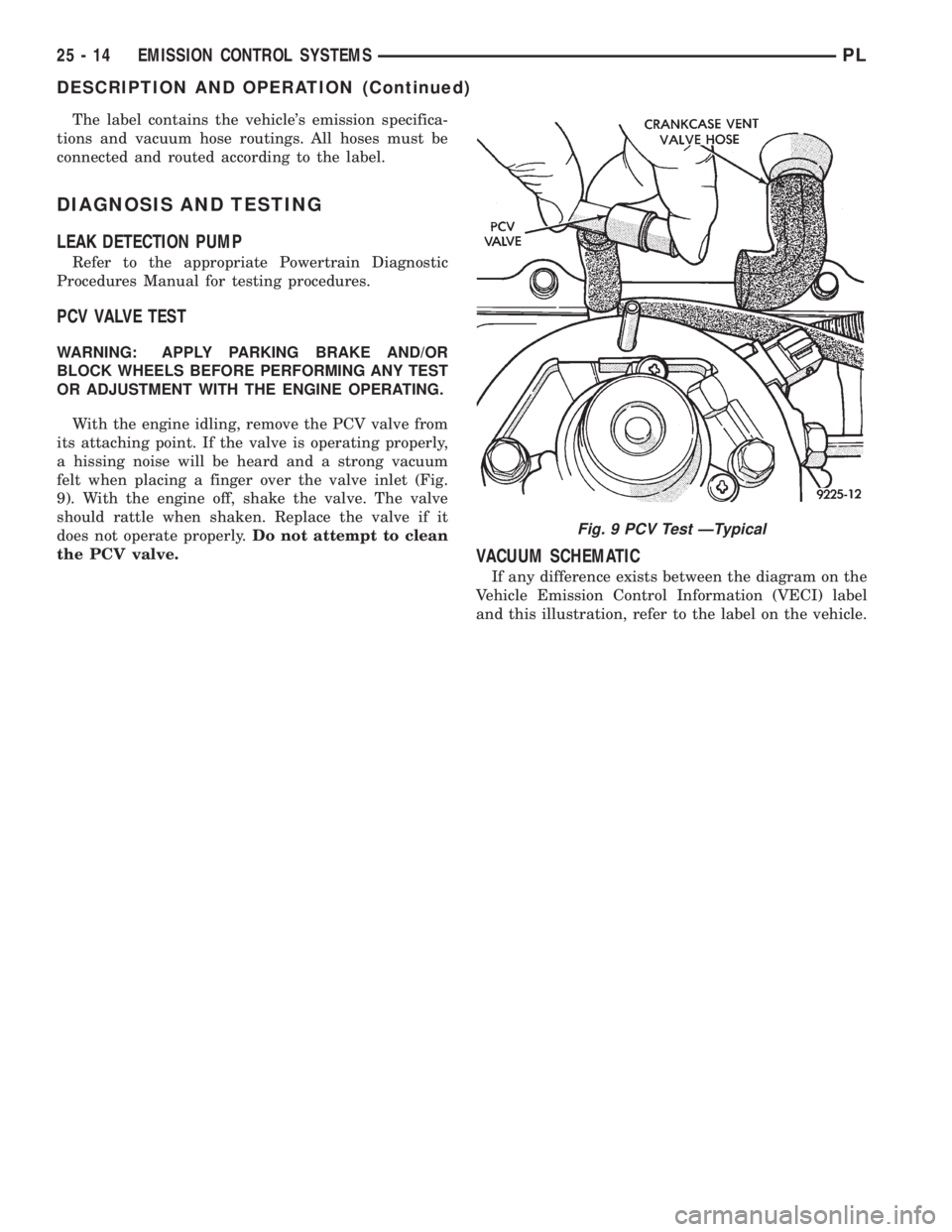
With the engine idling, remove the PCV valve from
its attaching point. If the valve is operating properly,
a hissing noise will be heard and a strong vacuum
felt when placing a finger over the valve inlet (Fig.
9). With the engine off, shake the valve. The valve
should rattle when shaken. Replace the valve if it
does not operate properly.Do not attempt to clean
the PCV valve.
VACUUM SCHEMATIC
If any difference exists between the diagram on the
Vehicle Emission Control Information (VECI) label
and this illustration, refer to the label on the vehicle.
Fig. 9 PCV Test ÐTypical
25 - 14 EMISSION CONTROL SYSTEMSPL
DESCRIPTION AND OPERATION (Continued)
Page 1182 of 1200

DIAGNOSIS AND TESTING
EGR SYSTEM ON-BOARD DIAGNOSTICS
The PCM performs an on-board diagnostic check of
the EGR system. The diagnostic system uses the
electronic EGR transducer for the system tests.
The diagnostic check activates only during selected
engine/driving conditions. When the conditions are
met, the PCM energizes the transducer solenoid to
disable the EGR. The PCM checks for a change in
the heated oxygen sensor signal. If the air-fuel mix-
ture goes lean, the PCM will attempt to enrichen the
mixture. The PCM registers a Diagnostic Trouble
Code (DTC) if the EGR system is not operating cor-
rectly. After registering a DTC, the PCM turns on the
malfunction indicator (Check Engine) lamp after 2
consecutive trips. There are 2 types of failures sensed
by the PCM. The first is a short or open in the elec-
trical solenoid circuit. the second is a mechhanical
failure or loss of vacuum. The Malfunction Indicator
Lamp (MIL) indicates the need for service.
If a problem is indicated by the MIL and a DTC for
the EGR system is set, check for proper operation of
the EGR system. Use the System Test, EGR Gas
Flow Test. If the EGR system tests properly, check
the system using the DRB scan tool. Refer to
On-Board Diagnosis sections in this Group. Also,
refer to the DRB scan tool and the appropriate Pow-
ertrain Diagnostics Procedure manual.
EGR SYSTEM TEST
WARNING: APPLY PARKING BRAKE AND/OR
BLOCK WHEELS BEFORE TESTING THE EGR SYS-
TEM.
(1) Check the condition of all EGR system hoses
and tubes for leaks, blockages, cracks, kinks and
hardening of rubber hoses. Repair and correct these
conditions before performing any tests.
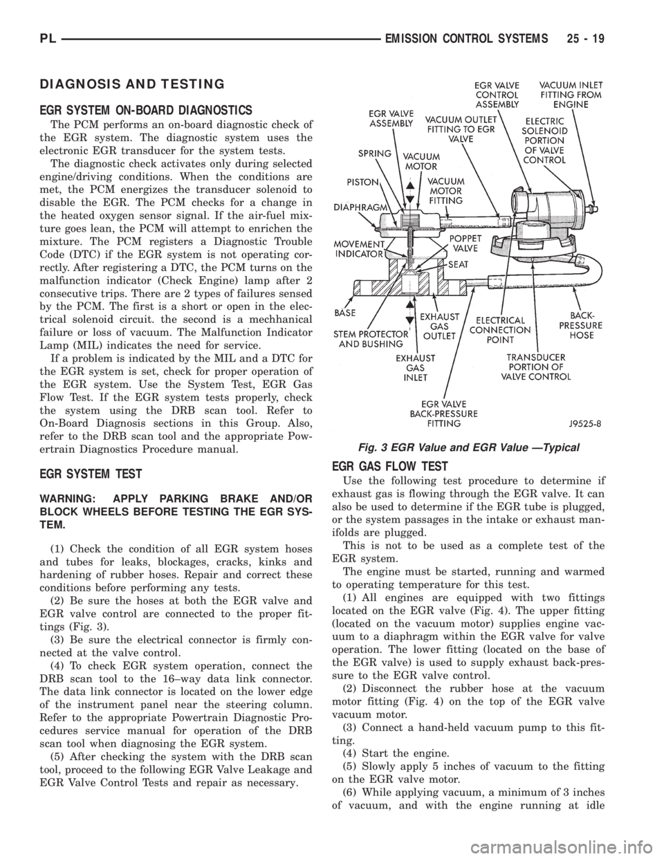
(2) Be sure the hoses at both the EGR valve and
EGR valve control are connected to the proper fit-
tings (Fig. 3).
(3) Be sure the electrical connector is firmly con-
nected at the valve control.
(4) To check EGR system operation, connect the
DRB scan tool to the 16±way data link connector.
The data link connector is located on the lower edge
of the instrument panel near the steering column.
Refer to the appropriate Powertrain Diagnostic Pro-
cedures service manual for operation of the DRB
scan tool when diagnosing the EGR system.
(5) After checking the system with the DRB scan
tool, proceed to the following EGR Valve Leakage and
EGR Valve Control Tests and repair as necessary.
EGR GAS FLOW TEST
Use the following test procedure to determine if
exhaust gas is flowing through the EGR valve. It can
also be used to determine if the EGR tube is plugged,
or the system passages in the intake or exhaust man-
ifolds are plugged.
This is not to be used as a complete test of the
EGR system.
The engine must be started, running and warmed
to operating temperature for this test.
(1) All engines are equipped with two fittings
located on the EGR valve (Fig. 4). The upper fitting
(located on the vacuum motor) supplies engine vac-
uum to a diaphragm within the EGR valve for valve
operation. The lower fitting (located on the base of
the EGR valve) is used to supply exhaust back-pres-
sure to the EGR valve control.
(2) Disconnect the rubber hose at the vacuum
motor fitting (Fig. 4) on the top of the EGR valve
vacuum motor.
(3) Connect a hand-held vacuum pump to this fit-
ting.
(4) Start the engine.
(5) Slowly apply 5 inches of vacuum to the fitting
on the EGR valve motor.
(6) While applying vacuum, a minimum of 3 inches
of vacuum, and with the engine running at idle
Fig. 3 EGR Value and EGR Value ÐTypical
PLEMISSION CONTROL SYSTEMS 25 - 19
Page 1195 of 1200
METRIC SYSTEM
WARNING: USE OF AN INCORRECT FASTENER
MAY RESULT IN COMPONENT DAMAGE OR PER-
SONAL INJURY.
Figure art, specifications and torque references in
this Service Manual are identified in metric and SAE
format.
During any maintenance or repair procedures, it is
important to salvage metric fasteners (nuts, bolts,
etc.) for reassembly. If the fastener is not salvage-
able, a fastener of equivalent specification should be
used.
The metric system is based on quantities of one,
ten, one hundred, one thousand and one million (Fig.
5).The following chart will assist in converting metric
units to equivalent English and SAE units, or vise
versa.
Refer to the Conversion Chart to convert torque
values listed in metric Newton meters (N´m). Also,
use the chart to convert between millimeters (mm)
and inches (in.).
CONVERSION FORMULAS AND EQUIVALENT VALUES
Fig. 5 Metric Prefixes
8 INTRODUCTIONPL
GENERAL INFORMATION (Continued)
Page 1200 of 1200

GROUP TAB LOCATOR
INIntroduction
INaIntroduction
0Lubrication and Maintenance
2Suspension
3Differential and Driveline
5Brakes
6Clutch
6aClutch
7Cooling
8ABattery
8BStarting
8CCharging System
8CaCharging System
8DIgnition System
8EInstrument Panel and Systems
8EaInstrument Panel and Systems
8FAudio System
8GHorns
8HVehicle Speed Control System
8HaVehicle Speed Control System
8JTurn Signal and Flashers
8KWindshield Wipers and Washers
8KaWindshield Wipers and Washers
8LLamps
8LaLamps
8MRestraint System
8NElectrically Heated Systems
8NaElectrically Heated Systems
8PPower Door Locks
8QaImmobilizer System
8SPower Windows
8TPower Mirrors
8TaPower Mirrors
8UChime Warning/Reminder System
8WWiring Diagrams - LHD and RHD
9Engine
9aEngine
11Exhaust System and Intake Manifold
11aExhaust System and Intake Manifold
13Frame and Bumpers
13aFrame and Bumpers
14Fuel System
14aFuel System - 1.8L Engine
19Steering
19aSteering
21Transaxle
21aTransaxle
22Tires and Wheels
23Body
24Heating and Air Conditioning
25Emission Control Systems
25aEmission Control System - 1.8L Engine