1999 DODGE NEON warning
[x] Cancel search: warningPage 919 of 1200
(2) Install power steering fluid supply hose on
power steering fluid reservoir fitting. Install hose
clamp on power steering fluid supply hose at power
steering fluid reservoir (Fig. 19).Be sure hose
clamp is installed on return hose past upset
bead on power steering fluid reservoir.
(3) Install power steering fluid supply hose on
power steering pump fitting. Install hose clamp on
power steering fluid supply hose at power steering
pump fitting (Fig. 20).Be sure hose clamp is
installed on power steering fluid supply hose
past upset bead on power steering pump fit-
ting.
(4) Start the engine and let run for a few seconds.
Then turn the engine off.
(5) Add fluid if necessary. Repeat the above proce-
dure until the fluid level remains constant after run-
ning the engine.
(6) Raise front wheels of vehicle off the ground.
(7) Start the engine. Slowly turn the steering
wheel right and left, lightly contacting the wheel
stops. Then turn the engine off.
(8) Add power steering fluid if necessary.
(9) Lower the vehicle and turn the steering wheel
slowly from lock to lock.
(10) Stop the engine. Check the fluid level and
refill as required.
(11) If the fluid is extremely foamy, allow the vehi-
cle to stand a few minutes and repeat the above pro-
cedure.
(12) After hose is installed, check for leaks at all
hose connections.
POWER STEERING PUMP (ALL ENGINES)
WARNING: POWER STEERING OIL, ENGINE COM-
PONENTS AND EXHAUST SYSTEM MAY BE
EXTREMELY HOT IF ENGINE HAS BEEN RUNNING.
DO NOT START ENGINE WITH ANY LOOSE OR DIS-
CONNECTED HOSES, OR ALLOW HOSES TO
TOUCH HOT EXHAUST MANIFOLD OR CATALYST.
The power steering pump removal procedure and
pump and bracket fastener locations are the same for
both engine applications used for this vehicle. The
front power steering pump bracket must be removed
as an assembly with the power steering pump and
removed from the pump after removing the pulley
from the power steering pump.
REMOVE
(1) Remove battery cable from (-) negative post on
battery.
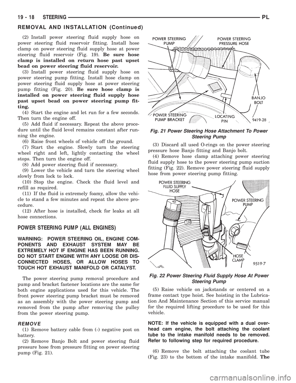
(2) Remove Banjo Bolt and power steering fluid
pressure hose from pressure fitting on power steering
pump (Fig. 21).(3) Discard all used O-rings on the power steering
pressure hose Banjo fitting and Banjo bolt.
(4) Remove hose clamp attaching power steering
fluid supply hose to the power steering pump suction
fitting (Fig. 22). Remove power steering fluid supply
hose from power steering pump fitting.
(5) Raise vehicle on jackstands or centered on a
frame contact type hoist. See hoisting in the Lubrica-
tion And Maintenance Section of this service manual
for the required lifting procedure to be used for this
vehicle.
NOTE: If the vehicle is equipped with a dual over-
head cam engine, the bolt attaching the coolant
tube to the intake manifold needs to be removed.
Refer to following step for required procedure.
(6) Remove the bolt attaching the coolant tube
(Fig. 23) to the bottom of the intake manifold.The
Fig. 21 Power Steering Hose Attachment To Power
Steering Pump
Fig. 22 Power Steering Fluid Supply Hose At Power
Steering Pump
19 - 18 STEERINGPL
REMOVAL AND INSTALLATION (Continued)
Page 936 of 1200
STEERING COLUMN
INDEX
page page
DESCRIPTION AND OPERATION
STEERING COLUMN ASSEMBLY............ 35
STEERING GEAR TO STEERING
COLUMN COUPLING................... 36
DIAGNOSIS AND TESTING
STEERING COLUMN TO STEERING
GEAR COUPLING...................... 36
STEERING COLUMN..................... 36REMOVAL AND INSTALLATION
STEERING COLUMN SERVICE
PROCEDURE WARNINGS............... 37
STEERING COLUMN..................... 38
SPECIFICATIONS
STEERING COLUMN FASTEER
TORQUE SPECIFICATIONS.............. 42
DESCRIPTION AND OPERATION
STEERING COLUMN ASSEMBLY
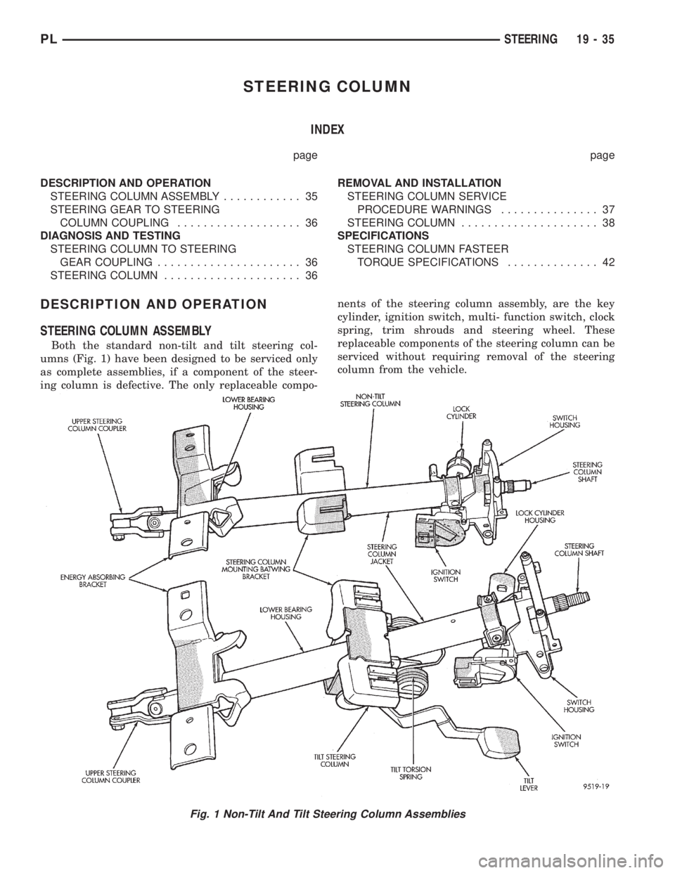
Both the standard non-tilt and tilt steering col-
umns (Fig. 1) have been designed to be serviced only
as complete assemblies, if a component of the steer-
ing column is defective. The only replaceable compo-nents of the steering column assembly, are the key
cylinder, ignition switch, multi- function switch, clock
spring, trim shrouds and steering wheel. These
replaceable components of the steering column can be
serviced without requiring removal of the steering
column from the vehicle.
Fig. 1 Non-Tilt And Tilt Steering Column Assemblies
PLSTEERING 19 - 35
Page 938 of 1200
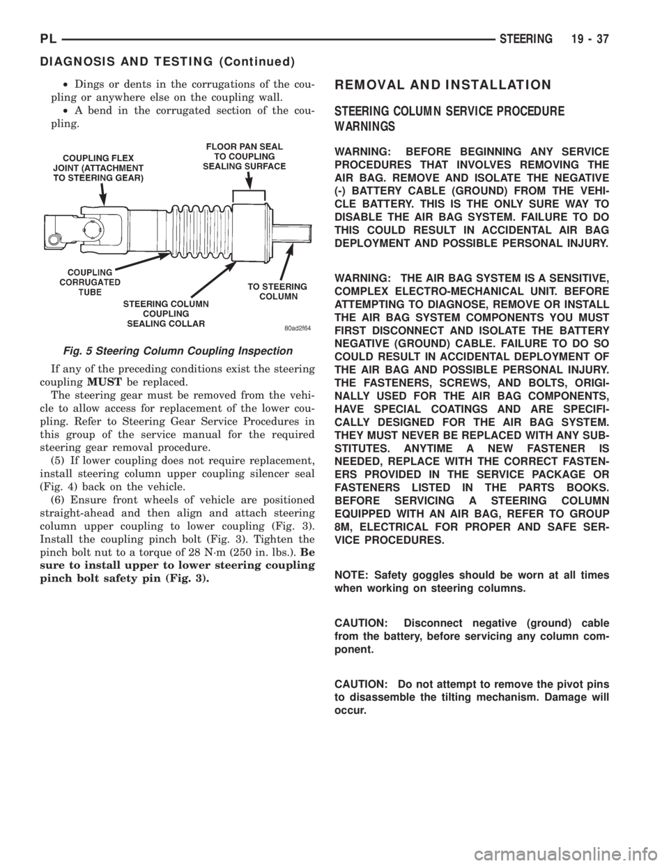
²Dings or dents in the corrugations of the cou-
pling or anywhere else on the coupling wall.
²A bend in the corrugated section of the cou-
pling.
If any of the preceding conditions exist the steering
couplingMUSTbe replaced.
The steering gear must be removed from the vehi-
cle to allow access for replacement of the lower cou-
pling. Refer to Steering Gear Service Procedures in
this group of the service manual for the required
steering gear removal procedure.
(5) If lower coupling does not require replacement,
install steering column upper coupling silencer seal
(Fig. 4) back on the vehicle.
(6) Ensure front wheels of vehicle are positioned
straight-ahead and then align and attach steering
column upper coupling to lower coupling (Fig. 3).
Install the coupling pinch bolt (Fig. 3). Tighten the
pinch bolt nut to a torque of 28 N´m (250 in. lbs.).Be
sure to install upper to lower steering coupling
pinch bolt safety pin (Fig. 3).REMOVAL AND INSTALLATION
STEERING COLUMN SERVICE PROCEDURE
WARNINGS
WARNING: BEFORE BEGINNING ANY SERVICE
PROCEDURES THAT INVOLVES REMOVING THE
AIR BAG. REMOVE AND ISOLATE THE NEGATIVE
(-) BATTERY CABLE (GROUND) FROM THE VEHI-
CLE BATTERY. THIS IS THE ONLY SURE WAY TO
DISABLE THE AIR BAG SYSTEM. FAILURE TO DO
THIS COULD RESULT IN ACCIDENTAL AIR BAG
DEPLOYMENT AND POSSIBLE PERSONAL INJURY.
WARNING: THE AIR BAG SYSTEM IS A SENSITIVE,
COMPLEX ELECTRO-MECHANICAL UNIT. BEFORE
ATTEMPTING TO DIAGNOSE, REMOVE OR INSTALL
THE AIR BAG SYSTEM COMPONENTS YOU MUST
FIRST DISCONNECT AND ISOLATE THE BATTERY
NEGATIVE (GROUND) CABLE. FAILURE TO DO SO
COULD RESULT IN ACCIDENTAL DEPLOYMENT OF
THE AIR BAG AND POSSIBLE PERSONAL INJURY.
THE FASTENERS, SCREWS, AND BOLTS, ORIGI-
NALLY USED FOR THE AIR BAG COMPONENTS,
HAVE SPECIAL COATINGS AND ARE SPECIFI-
CALLY DESIGNED FOR THE AIR BAG SYSTEM.
THEY MUST NEVER BE REPLACED WITH ANY SUB-
STITUTES. ANYTIME A NEW FASTENER IS
NEEDED, REPLACE WITH THE CORRECT FASTEN-
ERS PROVIDED IN THE SERVICE PACKAGE OR
FASTENERS LISTED IN THE PARTS BOOKS.
BEFORE SERVICING A STEERING COLUMN
EQUIPPED WITH AN AIR BAG, REFER TO GROUP
8M, ELECTRICAL FOR PROPER AND SAFE SER-
VICE PROCEDURES.
NOTE: Safety goggles should be worn at all times
when working on steering columns.
CAUTION: Disconnect negative (ground) cable
from the battery, before servicing any column com-
ponent.
CAUTION: Do not attempt to remove the pivot pins
to disassemble the tilting mechanism. Damage will
occur.
Fig. 5 Steering Column Coupling Inspection
PLSTEERING 19 - 37
DIAGNOSIS AND TESTING (Continued)
Page 939 of 1200
STEERING COLUMN
REMOVE
(1) Disconnect the negative (ground) cable from
the battery and isolate cable.
(2) Before beginning removal of steering column
assembly from vehicle, be sure front wheels of vehicle
are in thestraight aheadposition.
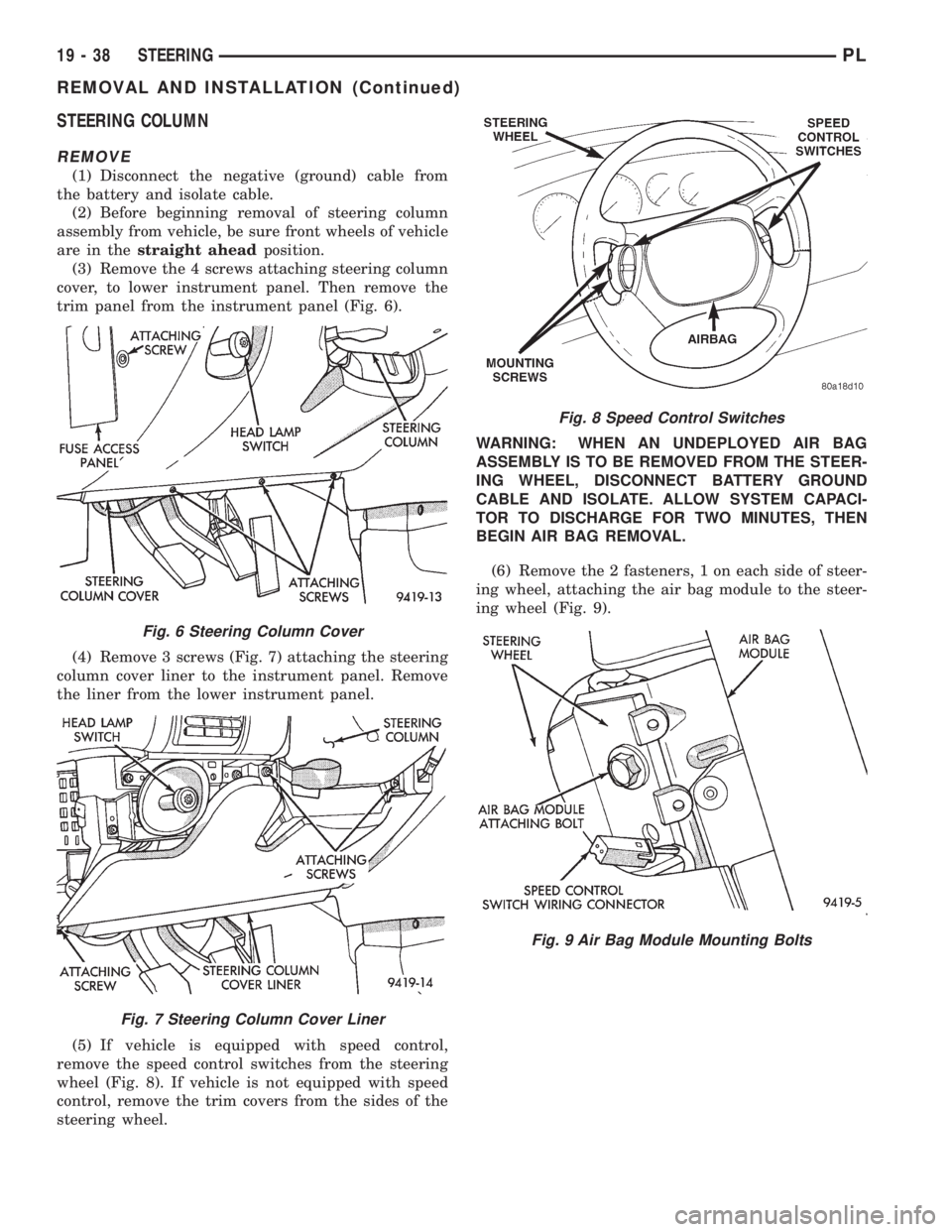
(3) Remove the 4 screws attaching steering column
cover, to lower instrument panel. Then remove the
trim panel from the instrument panel (Fig. 6).
(4) Remove 3 screws (Fig. 7) attaching the steering
column cover liner to the instrument panel. Remove
the liner from the lower instrument panel.
(5) If vehicle is equipped with speed control,
remove the speed control switches from the steering
wheel (Fig. 8). If vehicle is not equipped with speed
control, remove the trim covers from the sides of the
steering wheel.WARNING: WHEN AN UNDEPLOYED AIR BAG
ASSEMBLY IS TO BE REMOVED FROM THE STEER-
ING WHEEL, DISCONNECT BATTERY GROUND
CABLE AND ISOLATE. ALLOW SYSTEM CAPACI-
TOR TO DISCHARGE FOR TWO MINUTES, THEN
BEGIN AIR BAG REMOVAL.
(6) Remove the 2 fasteners, 1 on each side of steer-
ing wheel, attaching the air bag module to the steer-
ing wheel (Fig. 9).
Fig. 6 Steering Column Cover
Fig. 7 Steering Column Cover Liner
Fig. 8 Speed Control Switches
Fig. 9 Air Bag Module Mounting Bolts
19 - 38 STEERINGPL
REMOVAL AND INSTALLATION (Continued)
Page 940 of 1200
WARNING: WHEN HANDLING AN UNDEPLOYED
AIR BAG MODULE DURING SERVICING OF THE
STEERING COLUMN THE FOLLOWING PRECAU-
TIONS SHOULD BE OBSERVED. AT NO TIME
SHOULD ANY SOURCE OF ELECTRICITY BE PER-
MITTED NEAR THE INFLATOR ON THE BACK OF
THE AIR BAG MODULE. WHEN CARRYING A LIVE
MODULE, THE TRIM COVER SHOULD BE POINTED
AWAY FROM THE BODY TO MINIMIZE INJURY IF
MODULE ACCIDENTLY DEPLOYS. IF AIR BAG MOD-
ULE IS PLACED ON A BENCH OR OTHER SUR-
FACE, PLASTIC COVER SHOULD BE FACE UP TO
MINIMIZE MOVEMENT IN CASE OF ACCIDENTAL
DEPLOYMENT.
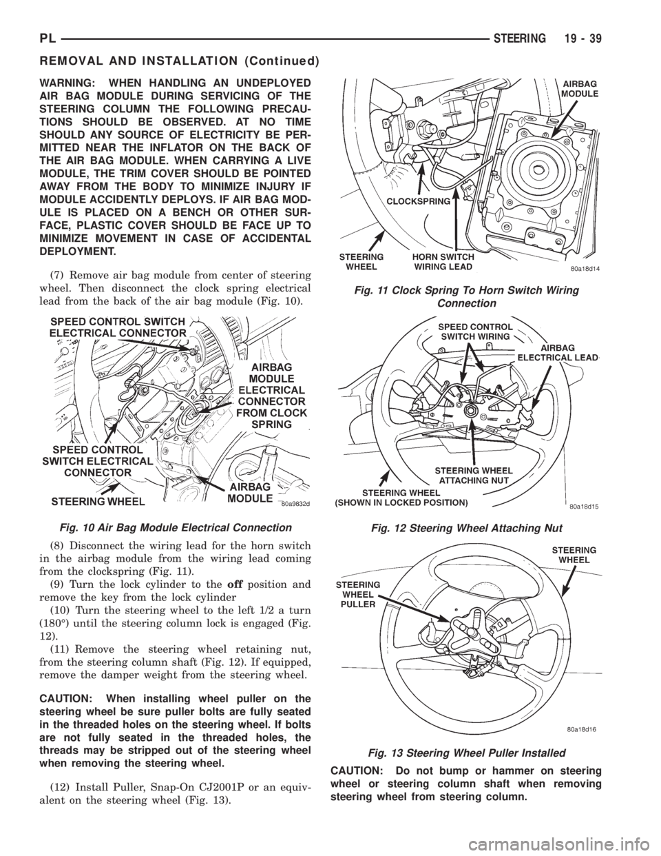
(7) Remove air bag module from center of steering
wheel. Then disconnect the clock spring electrical
lead from the back of the air bag module (Fig. 10).
(8) Disconnect the wiring lead for the horn switch
in the airbag module from the wiring lead coming
from the clockspring (Fig. 11).
(9) Turn the lock cylinder to theoffposition and
remove the key from the lock cylinder
(10) Turn the steering wheel to the left 1/2 a turn
(180É) until the steering column lock is engaged (Fig.
12).
(11) Remove the steering wheel retaining nut,
from the steering column shaft (Fig. 12). If equipped,
remove the damper weight from the steering wheel.
CAUTION: When installing wheel puller on the
steering wheel be sure puller bolts are fully seated
in the threaded holes on the steering wheel. If bolts
are not fully seated in the threaded holes, the
threads may be stripped out of the steering wheel
when removing the steering wheel.
(12) Install Puller, Snap-On CJ2001P or an equiv-
alent on the steering wheel (Fig. 13).CAUTION: Do not bump or hammer on steering
wheel or steering column shaft when removing
steering wheel from steering column.
Fig. 11 Clock Spring To Horn Switch Wiring
Connection
Fig. 12 Steering Wheel Attaching Nut
Fig. 13 Steering Wheel Puller Installed
Fig. 10 Air Bag Module Electrical Connection
PLSTEERING 19 - 39
REMOVAL AND INSTALLATION (Continued)
Page 943 of 1200
CAUTION: Do not install steering wheel onto shaft
of steering column assembly by driving it onto the
shaft. Pull steering wheel down onto steering col-
umn shaft using ONLY the steering wheel retaining
nut.
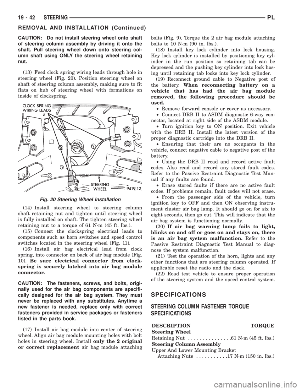
(13) Feed clock spring wiring leads through hole in
steering wheel (Fig. 20). Position steering wheel on
shaft of steering column assembly, making sure to fit
flats on hub of steering wheel with formations on
inside of clockspring.
(14) Install steering wheel to steering column
shaft retaining nut and tighten until steering wheel
is fully installed on shaft. The tighten steering wheel
retaining nut to a torque of 61 N´m (45 ft. lbs.).
(15) Connect the clockspring electrical leads to
components such as horn switches and speed control
switches located in the steering wheel (Fig. 11).
(16) Install air bag electrical lead from clock
spring, into connector on back of air bag module (Fig.
10).Be sure electrical connector from clock-
spring is securely latched into air bag module
connector.
CAUTION: The fasteners, screws, and bolts, origi-
nally used for the air bag components are specifi-
cally designed for the air bag system. They must
never be replaced with any substitutes. Anytime a
new fastener is needed, replace only with correct
fasteners provided in service packages or fasteners
listed in the parts book.
(17) Install air bag module into center of steering
wheel. Align air bag module mounting holes with bolt
holes in steering wheel. Installonly the 2 original
or correct replacementair bag module attachingbolts (Fig. 9). Torque the 2 air bag module attaching
bolts to 10 N´m (90 in. lbs.).
(18) Install key lock cylinder into lock housing.
Key lock cylinder is installed by positioning key cyl-
inder in the run position so retaining tab can be
depressed and the pushing key cylinder into lock hos-
ing until retaining tab locks into key lock cylinder.
(19) Reconnect ground cable to Negative post of
the battery.When reconnecting battery on a
vehicle that has had the air bag module
removed, the following procedure should be
used.
²Remove forward console or cover as necessary.
²Connect DRB II to ASDM diagnostic 6-way con-
nector, located at right side of the ASDM module.
²Turn ignition key to ON position. Exit vehicle
with the DRB II. Install the latest version of the
proper diagnostic cartridge into the DRB II.
²Ensuring that their are no occupants in the
vehicle, connect negative cable to negative post of the
battery.
²Using the DRB II read and record active fault
codes. Also read and record any stored fault codes.
Refer to the Passive Restraint Diagnostic Test Man-
ual if any faults are found.
²Erase stored faults if there are no active fault
codes. If problems remain, fault codes will not erase.
²From the passenger side of the vehicle, turn
ignition key to OFF and then ON observing instru-
ment cluster air bag lamp. It should go on for six to
eight seconds, then go out. This will indicate that the
air bag system is functioning normally.
(20)If air bag warning lamp fails to light,
blinks on and off or goes on and stays on, there
is an air bag system malfunction.Refer to the
Passive Restraint Diagnostic Test Manual to diag-
nose the system malfunction.
(21) Test the operation of the horn, lights and any
other functions that are steering column operated. If
applicable reset the radio and the clock.
(22) Road test vehicle to ensure proper operation
of the steering system and the speed control system.
SPECIFICATIONS
STEERING COLUMN FASTENER TORQUE
SPECIFICATIONS
DESCRIPTION TORQUE
Steering Wheel
Retaining Nut...............61N´m(45ft.lbs.)
Steering Column Assembly
Upper And Lower Mounting Bracket
Attaching Nuts...........17N´m(150 in. lbs.)
Fig. 20 Steering Wheel Installation
19 - 42 STEERINGPL
REMOVAL AND INSTALLATION (Continued)
Page 1001 of 1200
(8) Recheck fluid level after transaxle is at normal
operating temperature. The level should be in the
HOT region.
ALUMINUM THREAD REPAIR
Damaged or worn threads in the aluminum tran-
saxle case and valve body can be repaired by the use
of Heli-Coils. This repair consists of drilling out the
worn-out or damaged threads. Then tap the hole with
a Heli-Coil tap, and install a Heli-Coil insert into the
hole. This brings the hole back to its original thread
size.
Heli-Coil tools and inserts are readily available
from most automotive parts suppliers.
FLUSHING COOLERS AND TUBES
When a transaxle failure has contaminated the
fluid, the oil cooler(s) must be flushed. The cooler
bypass valve in the transaxle must be replaced also.
The torque converter must also be replaced with an
exchange unit. This will ensure that metal particles
or sludged oil are not later transferred back into the
reconditioned (or replaced) transaxle.
The recommended procedure for flushing the cool-
ers and tubes is to use Tool 6906A Cooler Flusher.
WARNING: WEAR PROTECTIVE EYEWEAR THAT
MEETS THE REQUIREMENTS OF OSHA AND ANSI
Z87.1±1968. WEAR STANDARD INDUSTRIAL RUB-
BER GLOVES.
KEEP LIGHTED CIGARETTES, SPARKS, FLAMES,
AND OTHER IGNITION SOURCES AWAY FROM THE
AREA TO PREVENT THE IGNITION OF COMBUSTI-
BLE LIQUIDS AND GASES. KEEP A CLASS (B) FIRE
EXTINGUISHER IN THE AREA WHERE THE
FLUSHER WILL BE USED.
KEEP THE AREA WELL VENTILATED.
DO NOT LET FLUSHING SOLVENT COME IN CON-
TACT WITH YOUR EYES OR SKIN: IF EYE CONTAM-
INATION OCCURS, FLUSH EYES WITH WATER FOR
15 TO 20 SECONDS. REMOVE CONTAMINATED
CLOTHING AND WASH AFFECTED SKIN WITH
SOAP AND WATER. SEEK MEDICAL ATTENTION.
COOLER FLUSH USING TOOL 6906A
(1) Remove cover plate filler plug on Tool 6906A.
Fill reservoir 1/2 to 3/4 full of fresh flushing solution.
Flushing solvents are petroleum based solutions gen-
erally used to clean automatic transmission compo-
nents.DO NOTuse solvents containing acids, water,
gasoline, or any other corrosive liquids.
(2) Reinstall filler plug on Tool 6906A.
(3) Verify pump power switch is turned OFF. Con-
nect red alligator clip to positive (+) battery post.
Connect black (-) alligator clip to a good ground.
(4) Disconnect the cooler lines at the transmission.NOTE: When flushing transmission cooler and
lines, ALWAYS reverse flush.
(5) Connect the BLUE pressure line to the OUT-
LET (From) cooler line.
(6) Connect the CLEAR return line to the INLET
(To) cooler line
(7) Turn pump ON for two to three minutes to
flush cooler(s) and lines. Monitor pressure readings
and clear return lines. Pressure readings should sta-
bilize below 20 psi. for vehicles equipped with a sin-
gle cooler and 30 psi. for vehicles equipped with dual
coolers. If flow is intermittent or exceeds these pres-
sures, replace cooler.
(8) Turn pump OFF.
(9) Disconnect CLEAR suction line from reservoir
at cover plate. Disconnect CLEAR return line at
cover plate, and place it in a drain pan.
(10) Turn pump ON for 30 seconds to purge flush-
ing solution from cooler and lines. Turn pump OFF.
(11) Place CLEAR suction line into a one quart
container of Mopar ATF Plus 3ttype 7176 automatic
transmission fluid.
(12) Turn pump ON until all transmission fluid is
removed from the one quart container and lines. This
purges any residual cleaning solvent from the trans-
mission cooler and lines. Turn pump OFF.
(13) Disconnect alligator clips from battery. Recon-
nect flusher lines to cover plate, and remove flushing
adapters from cooler lines.
OIL PUMP VOLUME CHECK
After the new or repaired transmission has been
installed, fill to the proper level with Mopar ATF
PLUS 3 (Type 7176) automatic transmission fluid.
The volume should be checked using the following
procedure:
(1) Disconnect theFrom coolerline at the trans-
mission and place a collecting container under the
disconnected line.
CAUTION: With the fluid set at the proper level,
fluid collection should not exceed (1) quart or inter-
nal damage to the transmission may occur.
(2) Run the engineat curb idle speed, with the
shift selector in neutral.
(3) If fluid flow is intermittent or it takes more
than 20 seconds to collect one quart of ATF, discon-
nect theTo Coolerline at the transaxle.
(4) Refill the transaxle to proper level and recheck
pump volume.
(5) If flow is found to be within acceptable limits,
replace the cooler. Then fill transmission to the
proper level, using Mopar ATF PLUS 3 (Type 7176)
automatic transmission fluid.
21 - 58 TRANSAXLEPL
SERVICE PROCEDURES (Continued)
Page 1040 of 1200
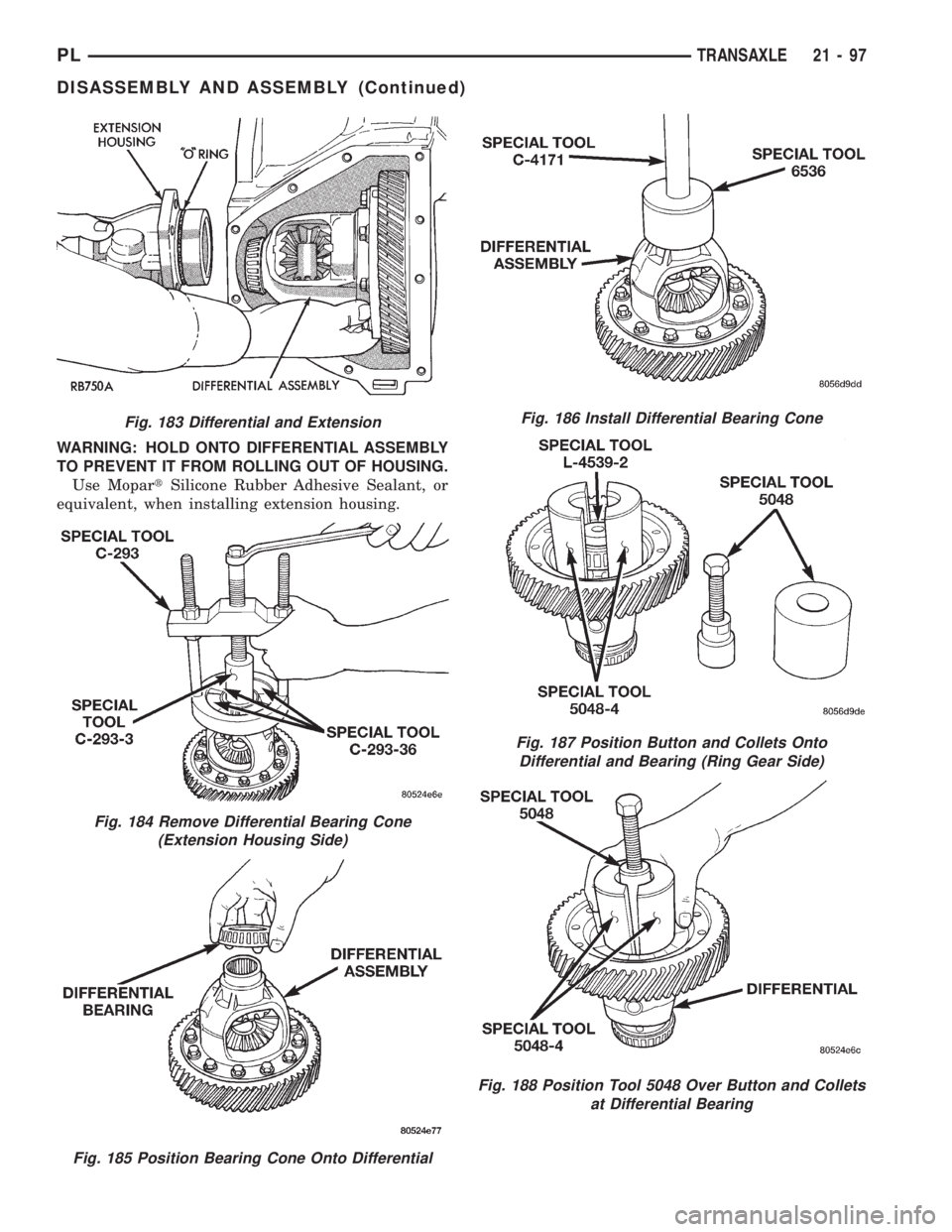
WARNING: HOLD ONTO DIFFERENTIAL ASSEMBLY
TO PREVENT IT FROM ROLLING OUT OF HOUSING.
Use MopartSilicone Rubber Adhesive Sealant, or
equivalent, when installing extension housing.
Fig. 183 Differential and Extension
Fig. 184 Remove Differential Bearing Cone
(Extension Housing Side)
Fig. 185 Position Bearing Cone Onto Differential
Fig. 186 Install Differential Bearing Cone
Fig. 187 Position Button and Collets Onto
Differential and Bearing (Ring Gear Side)
Fig. 188 Position Tool 5048 Over Button and Collets
at Differential Bearing
PLTRANSAXLE 21 - 97
DISASSEMBLY AND ASSEMBLY (Continued)