1999 DODGE NEON warning
[x] Cancel search: warningPage 853 of 1200
WARNING: THE FUEL RESERVOIR OF THE FUEL
PUMP MODULE DOES NOT EMPTY OUT WHEN THE
TANK IS DRAINED. THE FUEL IN THE RESERVOIR
WILL SPILL OUT WHEN THE MODULE IS
REMOVED.
(2) Disconnect fuel line from fuel pump module by
depressing quick connect retainers with thumb and
fore finger.
(3) Slide fuel pump module electrical connecter
lock to unlock.
(4) Disconnect the electrical connection from the
fuel pump module, by pushing down on connector
retainer and pulling connector off of module.
(5) Use a transmission jack to support the fuel
tank. remove bolts from fuel tank straps.
(6) Lower tank slightly.
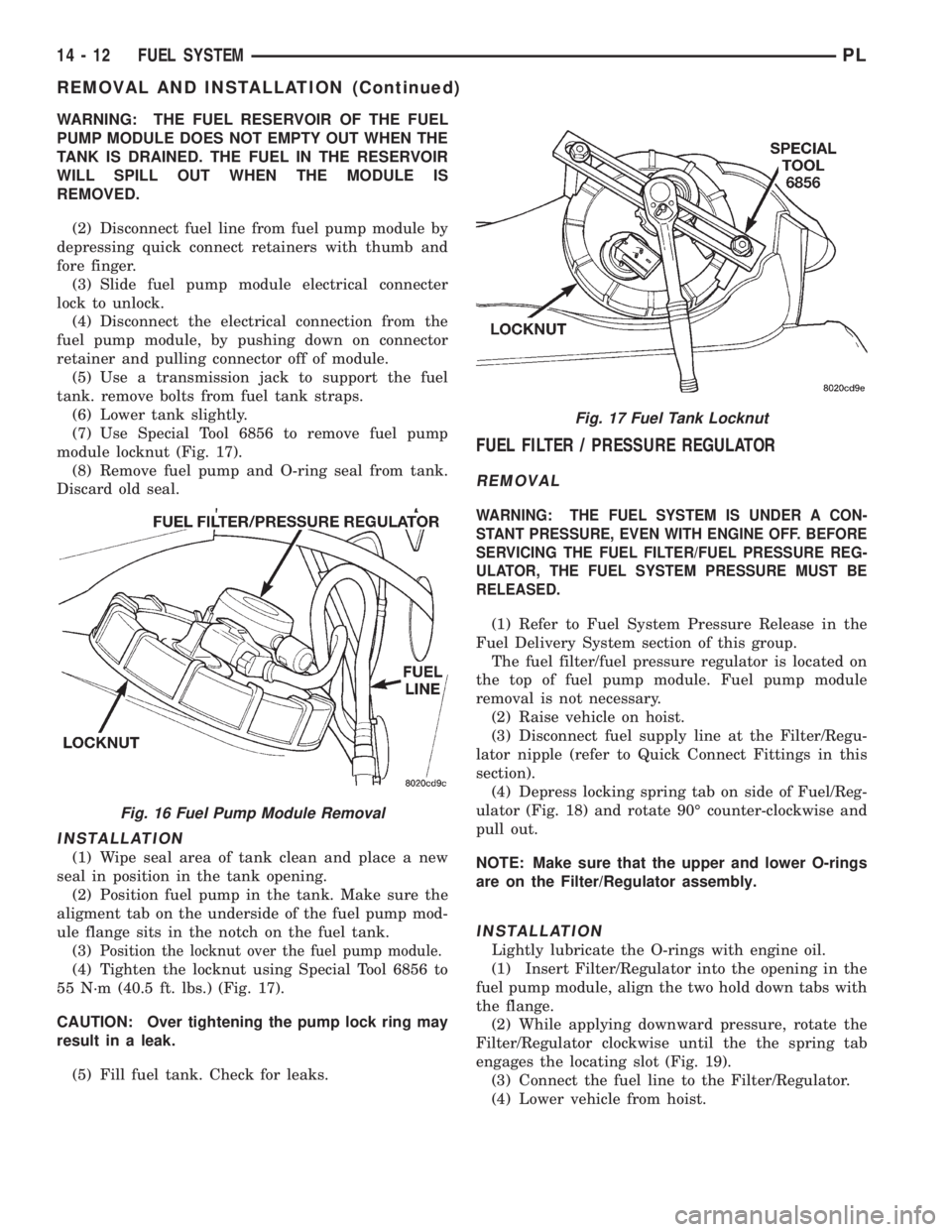
(7) Use Special Tool 6856 to remove fuel pump
module locknut (Fig. 17).
(8) Remove fuel pump and O-ring seal from tank.
Discard old seal.
INSTALLATION
(1) Wipe seal area of tank clean and place a new
seal in position in the tank opening.
(2) Position fuel pump in the tank. Make sure the
aligment tab on the underside of the fuel pump mod-
ule flange sits in the notch on the fuel tank.
(3)
Position the locknut over the fuel pump module.
(4) Tighten the locknut using Special Tool 6856 to
55 N´m (40.5 ft. lbs.) (Fig. 17).
CAUTION: Over tightening the pump lock ring may
result in a leak.
(5) Fill fuel tank. Check for leaks.
FUEL FILTER / PRESSURE REGULATOR
REMOVAL
WARNING: THE FUEL SYSTEM IS UNDER A CON-
STANT PRESSURE, EVEN WITH ENGINE OFF. BEFORE
SERVICING THE FUEL FILTER/FUEL PRESSURE REG-
ULATOR, THE FUEL SYSTEM PRESSURE MUST BE
RELEASED.
(1) Refer to Fuel System Pressure Release in the
Fuel Delivery System section of this group.
The fuel filter/fuel pressure regulator is located on
the top of fuel pump module. Fuel pump module
removal is not necessary.
(2) Raise vehicle on hoist.
(3) Disconnect fuel supply line at the Filter/Regu-
lator nipple (refer to Quick Connect Fittings in this
section).
(4) Depress locking spring tab on side of Fuel/Reg-
ulator (Fig. 18) and rotate 90É counter-clockwise and
pull out.
NOTE: Make sure that the upper and lower O-rings
are on the Filter/Regulator assembly.
INSTALLATION
Lightly lubricate the O-rings with engine oil.
(1) Insert Filter/Regulator into the opening in the
fuel pump module, align the two hold down tabs with
the flange.
(2) While applying downward pressure, rotate the
Filter/Regulator clockwise until the the spring tab
engages the locating slot (Fig. 19).
(3) Connect the fuel line to the Filter/Regulator.
(4) Lower vehicle from hoist.
Fig. 16 Fuel Pump Module Removal
Fig. 17 Fuel Tank Locknut
14 - 12 FUEL SYSTEMPL
REMOVAL AND INSTALLATION (Continued)
Page 856 of 1200
(5) Remove fuel rail mounting screws.
(6) Lift rail off of intake manifold. Cover the fuel
injector openings in the intake manifold.
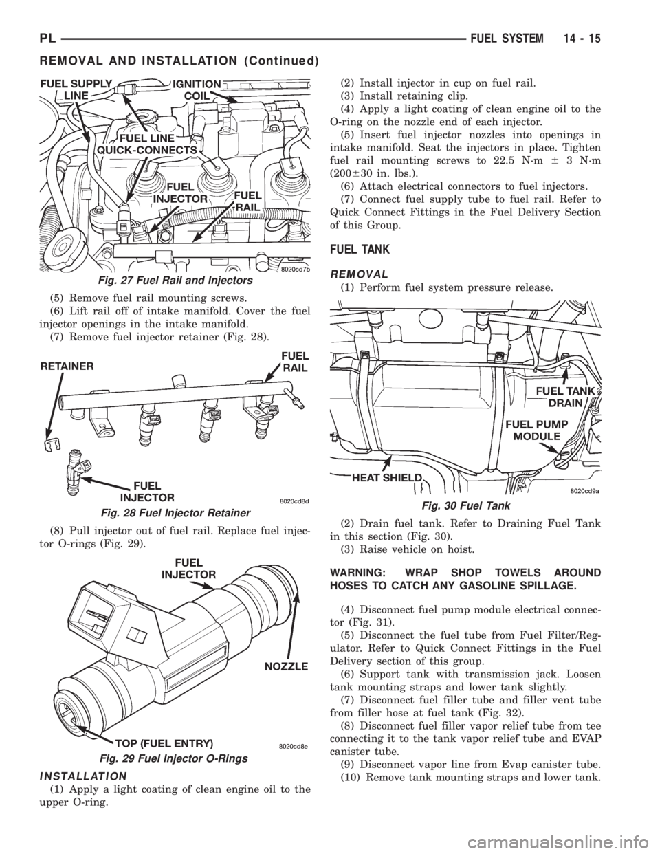
(7) Remove fuel injector retainer (Fig. 28).
(8) Pull injector out of fuel rail. Replace fuel injec-
tor O-rings (Fig. 29).
INSTALLATION
(1) Apply a light coating of clean engine oil to the
upper O-ring.(2) Install injector in cup on fuel rail.
(3) Install retaining clip.
(4) Apply a light coating of clean engine oil to the
O-ring on the nozzle end of each injector.
(5) Insert fuel injector nozzles into openings in
intake manifold. Seat the injectors in place. Tighten
fuel rail mounting screws to 22.5 N´m63 N´m
(200630 in. lbs.).
(6) Attach electrical connectors to fuel injectors.
(7) Connect fuel supply tube to fuel rail. Refer to
Quick Connect Fittings in the Fuel Delivery Section
of this Group.
FUEL TANK
REMOVAL
(1) Perform fuel system pressure release.
(2) Drain fuel tank. Refer to Draining Fuel Tank
in this section (Fig. 30).
(3) Raise vehicle on hoist.
WARNING: WRAP SHOP TOWELS AROUND
HOSES TO CATCH ANY GASOLINE SPILLAGE.
(4) Disconnect fuel pump module electrical connec-
tor (Fig. 31).
(5) Disconnect the fuel tube from Fuel Filter/Reg-
ulator. Refer to Quick Connect Fittings in the Fuel
Delivery section of this group.
(6) Support tank with transmission jack. Loosen
tank mounting straps and lower tank slightly.
(7) Disconnect fuel filler tube and filler vent tube
from filler hose at fuel tank (Fig. 32).
(8) Disconnect fuel filler vapor relief tube from tee
connecting it to the tank vapor relief tube and EVAP
canister tube.
(9) Disconnect vapor line from Evap canister tube.
(10) Remove tank mounting straps and lower tank.Fig. 27 Fuel Rail and Injectors
Fig. 28 Fuel Injector Retainer
Fig. 29 Fuel Injector O-Rings
Fig. 30 Fuel Tank
PLFUEL SYSTEM 14 - 15
REMOVAL AND INSTALLATION (Continued)
Page 887 of 1200
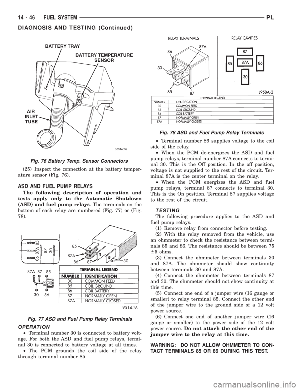
(25) Inspect the connection at the battery temper-
ature sensor (Fig. 76).
ASD AND FUEL PUMP RELAYS
The following description of operation and
tests apply only to the Automatic Shutdown
(ASD) and fuel pump relays. The terminals on the
bottom of each relay are numbered (Fig. 77) or (Fig.
78).
OPERATION
²Terminal number 30 is connected to battery volt-
age. For both the ASD and fuel pump relays, termi-
nal 30 is connected to battery voltage at all times.
²The PCM grounds the coil side of the relay
through terminal number 85.²Terminal number 86 supplies voltage to the coil
side of the relay.
²When the PCM de-energizes the ASD and fuel
pump relays, terminal number 87A connects to termi-
nal 30. This is the Off position. In the off position,
voltage is not supplied to the rest of the circuit. Ter-
minal 87A is the center terminal on the relay.
²When the PCM energizes the ASD and fuel
pump relays, terminal 87 connects to terminal 30.
This is the On position. Terminal 87 supplies voltage
to the rest of the circuit.
TESTING
The following procedure applies to the ASD and
fuel pump relays.
(1) Remove relay from connector before testing.
(2) With the relay removed from the vehicle, use
an ohmmeter to check the resistance between termi-
nals 85 and 86. The resistance should be between 75
65 ohms.
(3) Connect the ohmmeter between terminals 30
and 87A. The ohmmeter should show continuity
between terminals 30 and 87A.
(4) Connect the ohmmeter between terminals 87
and 30. The ohmmeter should not show continuity at
this time.
(5) Connect one end of a jumper wire (16 gauge or
smaller) to relay terminal 85. Connect the other end
of the jumper wire to the ground side of a 12 volt
power source.
(6) Connect one end of another jumper wire (16
gauge or smaller) to the power side of the 12 volt
power source.Do not attach the other end of the
jumper wire to the relay at this time.
WARNING: DO NOT ALLOW OHMMETER TO CON-
TACT TERMINALS 85 OR 86 DURING THIS TEST.
Fig. 76 Battery Temp. Sensor Connectors
Fig. 77 ASD and Fuel Pump Relay Terminals
Fig. 78 ASD and Fuel Pump Relay Terminals
14 - 46 FUEL SYSTEMPL
DIAGNOSIS AND TESTING (Continued)
Page 890 of 1200
(6) Connect the DRB scan tool to the data link
connector inside the passenger compartment.
(7) Run engine in Park or Neutral until the cooling
fan has cycled on and off at least once (180ÉF).
(8) Using the DRB scan tool, access Minimum Air-
flow Idle Speed.
(9) The following will then occur:
²Idle air control motor will fully close
²Idle spark advance will become fixed
²PCM will go open loop enriched
²DRB scan tool displays engine RPM
(10) If idle RPM is within the range shown in the
Idle Specification chart, throttle body minimum air-
flow is set correctly.
IDLE SPECIFICATION Ð2.0L ENGINEOdometer Reading Idle RPM
Below 1000 Miles.................550±1300 RPM
Above 1000 Miles.................600±1300 Miles
(11) If idle RPM is above specifications, use the
DRB scan tool to check idle air control motor opera-
tion. If idle air control motor is OK, replace throttle
body. If idle air flow is below specification, shut off
the engine and clean the throttle body as follows:
WARNING: CLEAN THROTTLE BODY IN A WELL
VENTILATED AREA. WEAR RUBBER OR BUTYL
GLOVES, DO NOT LET MOPAR PARTS CLEANER
COME IN CONTACT WITH EYES OR SKIN. AVOID
INGESTING THE CLEANER. WASH THOROUGHLY
AFTER USING CLEANER.
(a) Remove the throttle body from engine.
(b) While holding the throttle open, spray the
entire throttle body bore and the manifold side of
the throttle plate with Mopar Parts Cleaner.Only
use Mopar Parts Cleaner to clean the throttle
body.
(c) Using a soft scuff pad, clean the top and bot-
tom of throttle body bore and the edges and mani-
fold side of the throttle blade.The edges of the
throttle blade and portions of the throttle
bore that are closest to the throttle blade
when closed, must be free of deposits.
(d) Use compressed air to dry the throttle body.
(e) Inspect throttle body for foreign material.
(f) Install throttle body on manifold.
(g) Repeat steps 1 through 14. If the minimum
air flow is still not within specifications, the prob-
lem is not caused by the throttle body.
(12) Shut off engine.
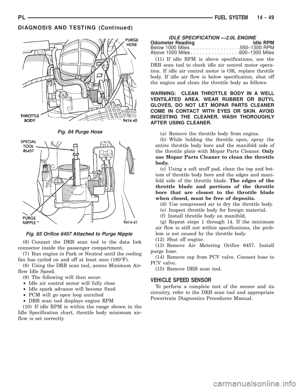
(13) Remove Air Metering Orifice 6457. Install
purge hose.
(14) Remove cap from PCV valve. Connect hose to
PCV valve.
(15) Remove DRB scan tool.
VEHICLE SPEED SENSOR
To perform a complete test of the sensor and its
circuitry, refer to the DRB scan tool and appropriate
Powertrain Diagnostics Procedures Manual.
Fig. 84 Purge Hose
Fig. 85 Orifice 6457 Attached to Purge Nipple
PLFUEL SYSTEM 14 - 49
DIAGNOSIS AND TESTING (Continued)
Page 912 of 1200
should be in the range of 345-552 kPa (50-80 psi).
The flow meter should read between 1.3 and 1.4
GPM
CAUTION: The following test procedure involves
testing power steering pump maximum pressure
output and flow control valve operation. Do not
leave valve closed for more than 5 seconds as the
pump could be damaged.
(8) Close valve fully three times and record high-
est pressure indicated each time.All three read-
ings must be above specifications and within
345 kPa (50 psi) of each other.
NOTE: Power steering pump maximum relief pres-
sure is 8240 to 8920 kPa (1195 to 1293 psi.).
²If power steering pump pressures above specifi-
cations but not within 345 kPa (50 psi) of each other,
then replace power steering pump.
²If pressures within 345 kPa (50 psi) of each
other but below specifications, then replace power
steering pump.
CAUTION: Do not force the pump to operate
against the stops for more than 5 seconds at a time
because, pump damage will result.
(9) Open test valve. Turn steering wheel to the
extreme left and right positions until against the
stops, recording the highest indicated pressure at
each position. Compare pressure gauge readings to
power steering pump specifications. If highest output
pressures are not the same against either stop, the
steering gear is leaking internally and must be
replaced.
SERVICE PROCEDURES
POWER STEERING SYSTEM FLUID LEVEL CHECK
WARNING: FLUID LEVEL SHOULD BE CHECKED
WITH ENGINE OFF TO PREVENT INJURY FROM
MOVING PARTS. DO NOT USE AUTOMATIC TRANS-
MISSION FLUID IN THE POWER STEERING SYS-
TEM. DO NOT OVERFILL THE POWER STEERING
SYSTEM.
Wipe reservoir filler cap free of dirt. Then check
fluid level. The dipstick should indicate COLD when
fluid is at normal ambient temperature, approxi-
mately 21ÉC to 27ÉC (70ÉF to 80ÉF). In all pumps add
fluid as necessary, use onlyMopar Power Steering
Fluid, or equivalent. DO NOT USE ANY TYPE
OF AUTOMATIC TRANSMISSION FLUID.
POWER STEERING PUMP INITIAL OPERATION
CAUTION: The fluid level should be checked with
engine off to prevent injury from moving compo-
nents. Use only MoparTPower Steering Fluid. Do
not use automatic transmission fluid. Do not over-
fill.
Wipe filler cap clean, then check the fluid level.
The dipstick should indicateFULL COLDwhen the
fluid is at normal temperature of approximately 21ÉC
to 27ÉC (70ÉF to 80ÉF).
(1) Fill the pump fluid reservoir to the proper level
and let the fluid settle for at least two (2) minutes.
(2) Start the engine and let run for a few seconds.
Then turn the engine off.
(3) Add fluid if necessary. Repeat the above proce-
dure until the fluid level remains constant after run-
ning the engine.
(4) Raise the front wheels off the ground.
(5) Start the engine. Slowly turn the steering
wheel right and left, lightly contacting the wheel
stops.
(6) Add power steering fluid if necessary.
(7) Lower the vehicle and turn the steering wheel
slowly from lock to lock.
(8) Stop the engine. Check the fluid level and refill
as required.
(9) If the fluid is extremely foamy, allow the vehi-
cle to stand a few minutes and repeat the above pro-
cedure.
POWER STEERING PUMP FLOW CONTROL VALVE
SEAL
The power steering pump does not require removal
from the engine for removal and replacement of the
flow control valve fitting O-Ring.
REMOVE
(1) Remove the power steering fluid pressure hose
from the power steering pump pressure fitting (Fig.
4).
(2) Remove the flow control valve fitting from the
power steering pump housing (Fig. 5).Prevent flow
control valve and spring from sliding out of
housing bore.
(3) Remove and discard O-ring seal from fitting.
INSTALL
(1) If necessary, clean and install flow control
valve and spring in pump housing bore.
(2) Install new O-ring seal on fitting.
(3) Install fitting in pump housing and tighten to
75 N´m (55 ft. lbs.)
(4) Install power steering fluid pressure hose on
flow control valve fitting.
PLSTEERING 19 - 11
DIAGNOSIS AND TESTING (Continued)
Page 914 of 1200
REMOVE
CAUTION: When removing and installing the
power steering pressure switch, the use of a 7/8
inch deep well socket is required. The deep well
socket will prevent damage to the plastic, electrical
connector area, of the power steering pressure
switch.
(1) Disconnect negative battery cable from the neg-
ative post of the battery. Be sure cable is isolated
from negative post on battery.
(2) Raise vehicle.
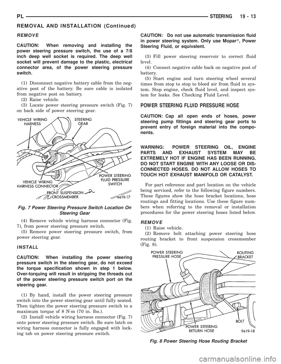
(3) Locate power steering pressure switch (Fig. 7)
on back side of power steering gear.
(4) Remove vehicle wiring harness connector (Fig.
7), from power steering pressure switch.
(5) Remove power steering pressure switch, from
power steering gear.
INSTALL
CAUTION: When installing the power steering
pressure switch in the steering gear, do not exceed
the torque specification shown in step 1 below.
Over-torquing will result in stripping the threads out
of the power steering pressure switch port on the
steering gear.
(1) By hand, install the power steering pressure
switch into the power steering gear until fully seated.
Then tighten the power steering pressure switch to a
maximum torque of 8 N´m (70 in. lbs.).
(2) Install vehicle wiring harness connector (Fig. 7)
onto power steering pressure switch. Be sure latch on
wiring harness connector is fully engaged with lock-
ing tab on power steering pressure switch.CAUTION: Do not use automatic transmission fluid
in power steering system. Only use MoparT, Power
Steering Fluid, or equivalent.
(3) Fill power steering reservoir to correct fluid
level.
(4) Connect negative cable back on negative post of
battery.
(5) Start engine and turn steering wheel several
times from stop to stop to bleed air from fluid in sys-
tem. Stop engine, check fluid level, and inspect sys-
tem for leaks. See Checking Fluid Level.
POWER STEERING FLUID PRESSURE HOSE
CAUTION: Cap all open ends of hoses, power
steering pump fittings and steering gear ports to
prevent entry of foreign material into the compo-
nents.
WARNING: POWER STEERING OIL, ENGINE
PARTS AND EXHAUST SYSTEM MAY BE
EXTREMELY HOT IF ENGINE HAS BEEN RUNNING.
DO NOT START ENGINE WITH ANY LOOSE OR DIS-
CONNECTED HOSES. DO NOT ALLOW HOSES TO
TOUCH HOT EXHAUST MANIFOLD OR CATALYST.
For part reference and part location on the vehicle
being serviced, refer to the following figure numbers.
These figures show the hose bracket locations, hose
routings and fitting locations. Use these figure num-
bers when referring to the removal or installation
procedures for the power steering hoses listed below.
REMOVE
(1) Raise vehicle.
(2) Remove bolt attaching power steering hose
routing bracket to front suspension crossmember
(Fig. 8).
Fig. 7 Power Steering Pressure Switch Location On
Steering Gear
Fig. 8 Power Steering Hose Routing Bracket
PLSTEERING 19 - 13
REMOVAL AND INSTALLATION (Continued)
Page 916 of 1200
(8) Correctly route power steering pressure hose
avoiding tight bends or kinking of the hose. Install
power steering pressure hose to generator shield
routing clip attaching screw (Fig. 11)but do not
tighten at this time.
(9) Raise vehicle.
CAUTION: Hoses must remain away from exhaust
system, vehicle components and unfriendly sur-
faces causing possible damage to power steering
hoses.
(10) Route power steering pressure hose to pres-
sure port on power steering gear. Install power steer-
ing pressure hose, on steering gear and loosely
install tube nut into steering gear (Fig. 9).Tighten
and torque tube nut after routing bracket is
installed, correctly positioning hoses in vehicle.(11) Install the power steering pressure and return
hose routing clip on hoses (Fig. 8). Install bolt attach-
ing routing clip to front suspension crossmember.
Torque routing clip to front suspension crossmember
attaching bolt to 23 N´m (17 ft. lbs.)
(12) Torque power steering pressure hose to steer-
ing gear tube nut to 34 N´m (25 ft. lbs.).
(13) Install power steering pressure hose in rout-
ing clip on generator shield (Fig. 10).
(14) Lower Vehicle.
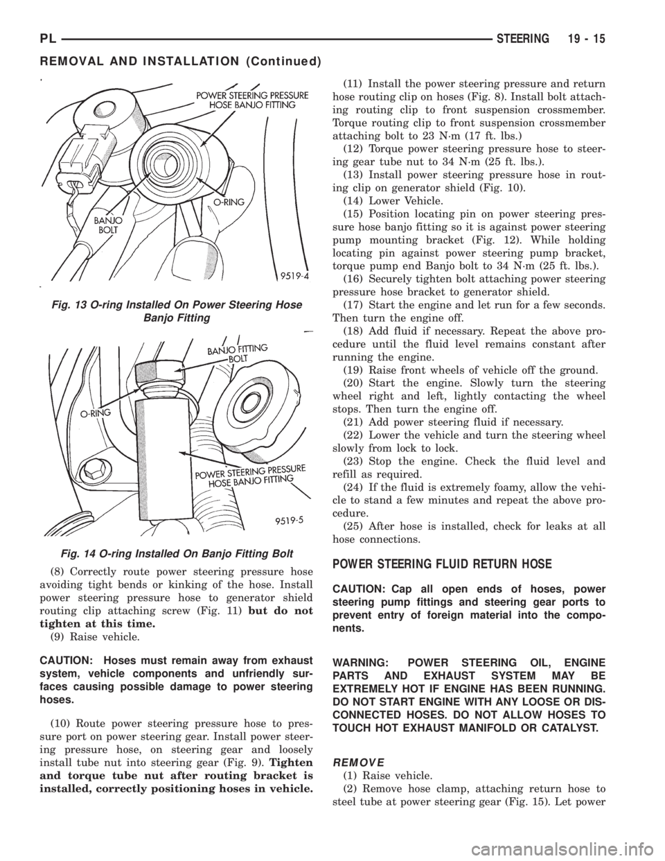
(15) Position locating pin on power steering pres-
sure hose banjo fitting so it is against power steering
pump mounting bracket (Fig. 12). While holding
locating pin against power steering pump bracket,
torque pump end Banjo bolt to 34 N´m (25 ft. lbs.).
(16) Securely tighten bolt attaching power steering
pressure hose bracket to generator shield.
(17) Start the engine and let run for a few seconds.
Then turn the engine off.
(18) Add fluid if necessary. Repeat the above pro-
cedure until the fluid level remains constant after
running the engine.
(19) Raise front wheels of vehicle off the ground.
(20) Start the engine. Slowly turn the steering
wheel right and left, lightly contacting the wheel
stops. Then turn the engine off.
(21) Add power steering fluid if necessary.
(22) Lower the vehicle and turn the steering wheel
slowly from lock to lock.
(23) Stop the engine. Check the fluid level and
refill as required.
(24) If the fluid is extremely foamy, allow the vehi-
cle to stand a few minutes and repeat the above pro-
cedure.
(25) After hose is installed, check for leaks at all
hose connections.POWER STEERING FLUID RETURN HOSE
CAUTION: Cap all open ends of hoses, power
steering pump fittings and steering gear ports to
prevent entry of foreign material into the compo-
nents.
WARNING: POWER STEERING OIL, ENGINE
PARTS AND EXHAUST SYSTEM MAY BE
EXTREMELY HOT IF ENGINE HAS BEEN RUNNING.
DO NOT START ENGINE WITH ANY LOOSE OR DIS-
CONNECTED HOSES. DO NOT ALLOW HOSES TO
TOUCH HOT EXHAUST MANIFOLD OR CATALYST.
REMOVE
(1) Raise vehicle.
(2) Remove hose clamp, attaching return hose to
steel tube at power steering gear (Fig. 15). Let power
Fig. 13 O-ring Installed On Power Steering Hose
Banjo Fitting
Fig. 14 O-ring Installed On Banjo Fitting Bolt
PLSTEERING 19 - 15
REMOVAL AND INSTALLATION (Continued)
Page 918 of 1200
installed on return hose past upset bead on
power steering fluid reservoir.
(3) Raise vehicle.
(4) Clip power steering return hose and pressure
hose together (Fig. 17).
(5) Install power steering return hose on steel tube
at power steering gear (Fig. 15). Install hose clamp
on power steering return hose at power steering gear
(Fig. 15).Be sure hose clamp is installed on
return hose past upset bead on steel tube at
power gear.
(6) Install power steering return hose on routing
clip at generator shield (Fig. 16).
(7) Lower vehicle.
(8) Start the engine and let run for a few seconds.
Then turn the engine off.
(9) Add fluid if necessary. Repeat the above proce-
dure until the fluid level remains constant after run-
ning the engine.
(10) Raise front wheels of vehicle off the ground.
(11) Start the engine. Slowly turn the steering
wheel right and left, lightly contacting the wheel
stops. Then turn the engine off.
(12) Add power steering fluid if necessary.
(13) Lower the vehicle and turn the steering wheel
slowly from lock to lock.
(14) Stop the engine. Check the fluid level and
refill as required.
(15) If the fluid is extremely foamy, allow the vehi-
cle to stand a few minutes and repeat the above pro-
cedure.
(16) After hose is installed, check for leaks at all
hose connections.
POWER STEERING FLUID SUPPLY HOSE
RESERVOIR TO POWER STEERING PUMP
WARNING: POWER STEERING OIL, ENGINE
PARTS AND EXHAUST SYSTEM MAY BE
EXTREMELY HOT IF ENGINE HAS BEEN RUNNING.
DO NOT START ENGINE WITH ANY LOOSE OR DIS-
CONNECTED HOSES. DO NOT ALLOW HOSES TO
TOUCH HOT EXHAUST MANIFOLD OR CATALYST.
REMOVE
CAUTION: Care must be used when removing the
power steering fluid supply hose from power steer-
ing fluid reservoir. If excessive force is used when
trying to remove hose from nipple on power steer-
ing fluid reservoir, nipple can break off of the res-
ervoir.
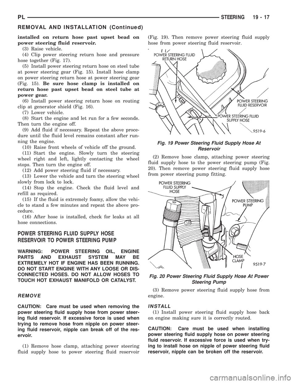
(1) Remove hose clamp, attaching power steering
fluid supply hose to power steering fluid reservoir(Fig. 19). Then remove power steering fluid supply
hose from power steering fluid reservoir.
(2) Remove hose clamp, attaching power steering
fluid supply hose to the power steering pump (Fig.
20). Then remove power steering fluid supply hose
from power steering pump fitting.
(3) Remove power steering fluid supply hose from
engine.INSTALL
(1) Install power steering fluid supply hose back
on engine making sure it is correctly routed.
CAUTION: Care must be used when installing
power steering fluid supply hose on power steering
fluid reservoir. If excessive force is used when try-
ing to install hose on nipple of power steering fluid
reservoir, nipple can be broken off the reservoir.
Fig. 19 Power Steering Fluid Supply Hose At
Reservoir
Fig. 20 Power Steering Fluid Supply Hose At Power
Steering Pump
PLSTEERING 19 - 17
REMOVAL AND INSTALLATION (Continued)