1999 DODGE NEON warning
[x] Cancel search: warningPage 1070 of 1200
weather temperature varies widely. Tire pressure will
decrease when the outdoor temperature drops.
Inflation pressures specified on the placard are
always the cold inflation pressure of the tire. Cold
inflation pressure is obtained after the vehicle has
not been operated for at least 3 hours, or the vehicle
is driven less than one mile after being inoperative
for 3 hours. Tire inflation pressures may increase
from 2 to 6 pounds per square inch (psi) during oper-
ation. Do not reduce this normal pressure build-up.
WARNING: OVER OR UNDER INFLATED TIRES
CAN AFFECT VEHICLE HANDLING. THE TIRE CAN
FAIL SUDDENLY, RESULTING IN LOSS OF VEHICLE
CONTROL.
TIRE PRESSURE FOR HIGH SPEED OPERATION
Chrysler Corporation advocates driving at safe
speeds within posted speed limits. Where speed lim-
its allow the vehicle to be driven at high speeds, cor-
rect tire inflation pressure is very important. For
speeds up to and including 120 km/h (75 mph), tires
must be inflated to the pressures shown on the tire
placard. For continuous speeds in excess of 120 km/h
(75 mph), tires must be inflated to the maximum
pressure specified on the tire sidewall.
Vehicles loaded to the maximum capacity should
not be driven at continuous speeds above 75 mph
(120 km/h).
For emergency vehicles that are driven at speeds
over 90 mph (144 km/h), special high speed tires
must be used. Consult tire manufacturer for correct
inflation pressure recommendations.
REPLACEMENT TIRES
The original equipment tires provide a proper bal-
ance of many characteristics such as:
²Ride
²Noise
²Handling
²Durability
²Tread life
²Traction
²Rolling resistance
²Speed capability
It is recommend that tires equivalent to the origi-
nal equipment tires be used when replacement is
needed.
Failure to use equivalent replacement tires may
adversely affect the safety and handling of the vehi-
cle.
The use of oversize tires not listed in the specifica-
tion charts may cause interference with vehicle com-
ponents. Under extremes of suspension and steering
travel, interference with vehicle components may
cause tire damage.WARNING: FAILURE TO EQUIP THE VEHICLE WITH
TIRES HAVING ADEQUATE SPEED CAPABILITY
CAN RESULT IN SUDDEN TIRE FAILURE.
DIAGNOSIS AND TESTING
PRESSURE GAUGES
A quality air pressure gauge is recommended to
check tire pressure. After checking the air pressure,
replace valve cap finger tight.
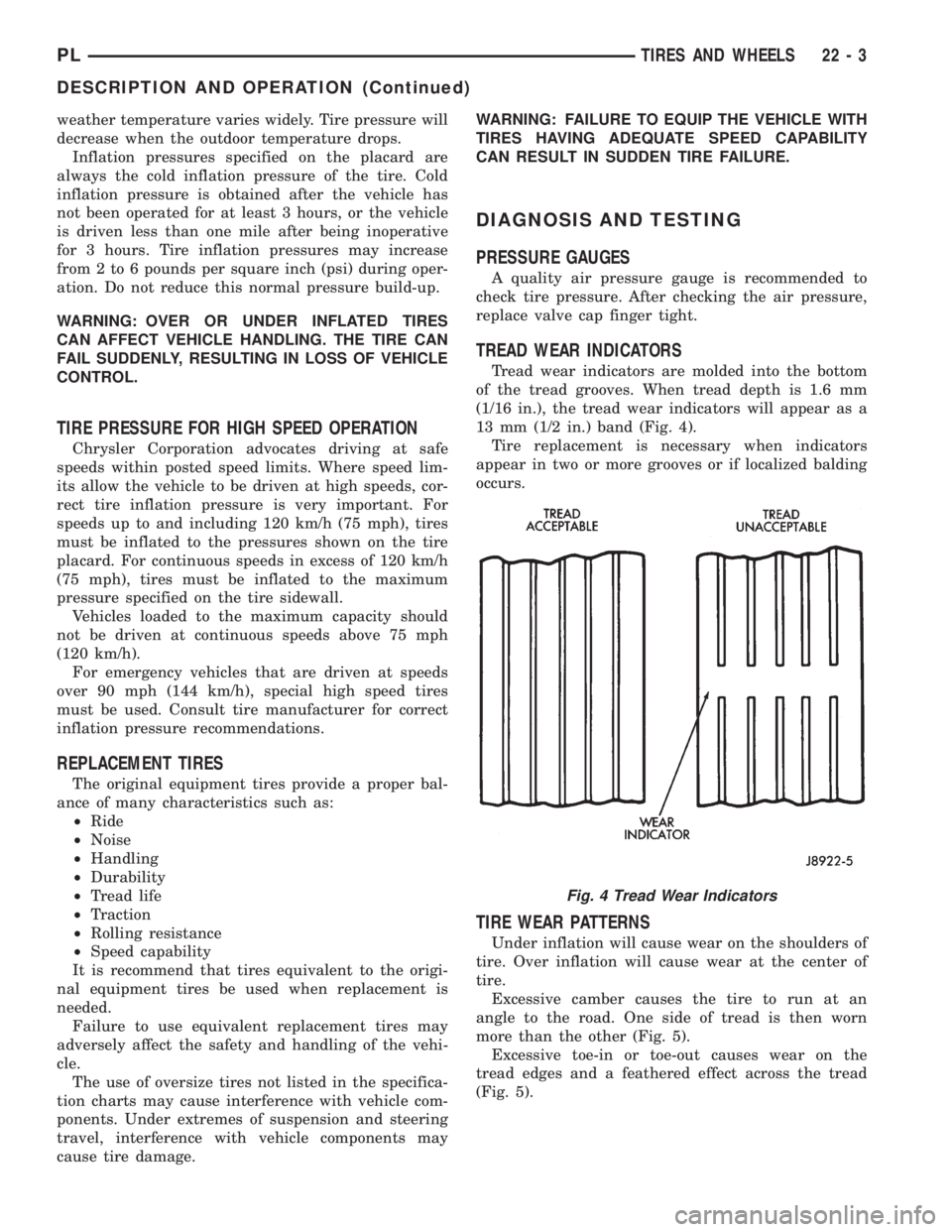
TREAD WEAR INDICATORS
Tread wear indicators are molded into the bottom
of the tread grooves. When tread depth is 1.6 mm
(1/16 in.), the tread wear indicators will appear as a
13 mm (1/2 in.) band (Fig. 4).
Tire replacement is necessary when indicators
appear in two or more grooves or if localized balding
occurs.
TIRE WEAR PATTERNS
Under inflation will cause wear on the shoulders of
tire. Over inflation will cause wear at the center of
tire.
Excessive camber causes the tire to run at an
angle to the road. One side of tread is then worn
more than the other (Fig. 5).
Excessive toe-in or toe-out causes wear on the
tread edges and a feathered effect across the tread
(Fig. 5).
Fig. 4 Tread Wear Indicators
PLTIRES AND WHEELS 22 - 3
DESCRIPTION AND OPERATION (Continued)
Page 1075 of 1200
WHEELS
INDEX
page page
DESCRIPTION AND OPERATION
WHEEL COVER (LOCK-ON)................. 8
WHEEL INFORMATION.................... 8
DIAGNOSIS AND TESTING
TIRE AND WHEEL RUNOUT................ 9
WHEEL INSPECTION...................... 9
SERVICE PROCEDURES
TIRE AND WHEEL BALANCE............... 10REMOVAL AND INSTALLATION
WHEEL AND TIRE....................... 12
WHEEL COVER (LOCK-ON)................ 12
WHEEL COVER RETAINING NUT........... 13
SPECIFICATIONS
WHEEL SPECIFICATIONS................. 14
DESCRIPTION AND OPERATION
WHEEL INFORMATION
Original equipment wheels are designed for proper
operation at all loads up to the specified maximum
vehicle capacity.
All models use steel or cast aluminum drop center
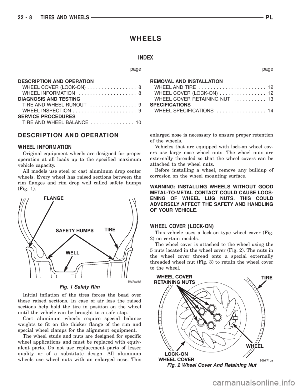
wheels. Every wheel has raised sections between the
rim flanges and rim drop well called safety humps
(Fig. 1).
Initial inflation of the tires forces the bead over
these raised sections. In case of air loss the raised
sections help hold the tire in position on the wheel
until the vehicle can be brought to a safe stop.
Cast aluminum wheels require special balance
weights to fit on the thicker flange of the rim and
special wheel clamps for the alignment equipment.
The wheel studs and nuts are designed for specific
wheel applications and must be replaced with equiv-
alent parts. Do not use replacement parts of lesser
quality or of a substitute design. All aluminum
wheels use wheel nuts with an enlarged nose. Thisenlarged nose is necessary to ensure proper retention
of the wheels.
Vehicles that are equipped with lock-on wheel cov-
ers use large nose wheel nuts. The wheel nuts are
externally threaded so that the wheel covers can be
attached to the wheel nuts.
Before installing a wheel, remove any buildup of
corrosion on the wheel mounting surface.
WARNING: INSTALLING WHEELS WITHOUT GOOD
METAL-TO-METAL CONTACT COULD CAUSE LOOS-
ENING OF WHEEL LUG NUTS. THIS COULD
ADVERSELY AFFECT THE SAFETY AND HANDLING
OF YOUR VEHICLE.
WHEEL COVER (LOCK-ON)
This vehicle uses a lock-on type wheel cover (Fig.
2) on certain models.
The wheel cover is attached to the wheel using the
5 nuts located in the wheel cover (Fig. 2). The nuts in
the wheel cover thread onto a special externally
threaded wheel nut (Fig. 3) to retain the wheel cover
to the wheel.
Fig. 1 Safety Rim
Fig. 2 Wheel Cover And Retaining Nut
22 - 8 TIRES AND WHEELSPL
Page 1076 of 1200
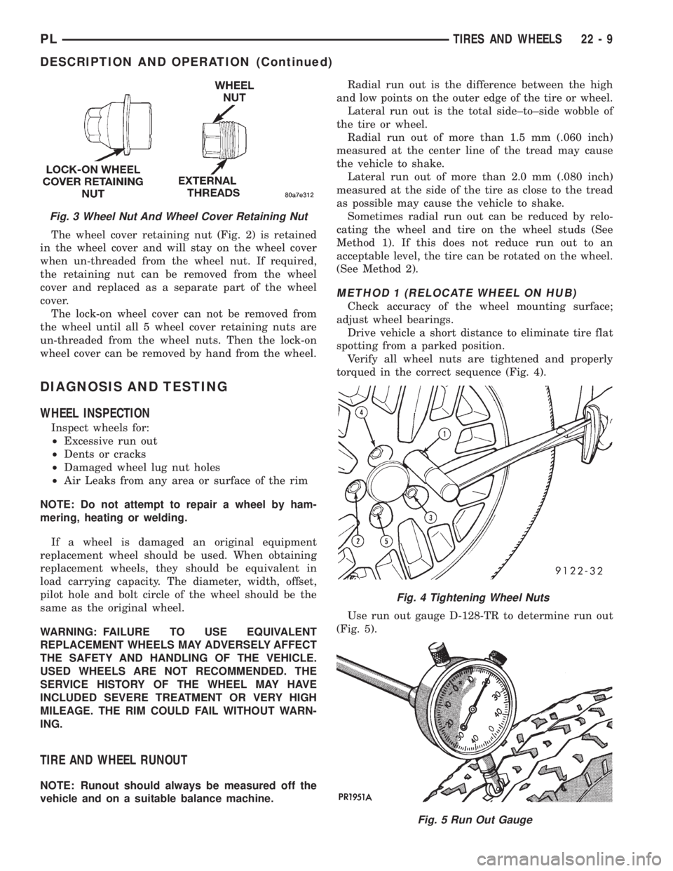
The wheel cover retaining nut (Fig. 2) is retained
in the wheel cover and will stay on the wheel cover
when un-threaded from the wheel nut. If required,
the retaining nut can be removed from the wheel
cover and replaced as a separate part of the wheel
cover.
The lock-on wheel cover can not be removed from
the wheel until all 5 wheel cover retaining nuts are
un-threaded from the wheel nuts. Then the lock-on
wheel cover can be removed by hand from the wheel.
DIAGNOSIS AND TESTING
WHEEL INSPECTION
Inspect wheels for:
²Excessive run out
²Dents or cracks
²Damaged wheel lug nut holes
²Air Leaks from any area or surface of the rim
NOTE: Do not attempt to repair a wheel by ham-
mering, heating or welding.
If a wheel is damaged an original equipment
replacement wheel should be used. When obtaining
replacement wheels, they should be equivalent in
load carrying capacity. The diameter, width, offset,
pilot hole and bolt circle of the wheel should be the
same as the original wheel.
WARNING: FAILURE TO USE EQUIVALENT
REPLACEMENT WHEELS MAY ADVERSELY AFFECT
THE SAFETY AND HANDLING OF THE VEHICLE.
USED WHEELS ARE NOT RECOMMENDED. THE
SERVICE HISTORY OF THE WHEEL MAY HAVE
INCLUDED SEVERE TREATMENT OR VERY HIGH
MILEAGE. THE RIM COULD FAIL WITHOUT WARN-
ING.
TIRE AND WHEEL RUNOUT
NOTE: Runout should always be measured off the
vehicle and on a suitable balance machine.Radial run out is the difference between the high
and low points on the outer edge of the tire or wheel.
Lateral run out is the total side±to±side wobble of
the tire or wheel.
Radial run out of more than 1.5 mm (.060 inch)
measured at the center line of the tread may cause
the vehicle to shake.
Lateral run out of more than 2.0 mm (.080 inch)
measured at the side of the tire as close to the tread
as possible may cause the vehicle to shake.
Sometimes radial run out can be reduced by relo-
cating the wheel and tire on the wheel studs (See
Method 1). If this does not reduce run out to an
acceptable level, the tire can be rotated on the wheel.
(See Method 2).
METHOD 1 (RELOCATE WHEEL ON HUB)
Check accuracy of the wheel mounting surface;
adjust wheel bearings.
Drive vehicle a short distance to eliminate tire flat
spotting from a parked position.
Verify all wheel nuts are tightened and properly
torqued in the correct sequence (Fig. 4).
Use run out gauge D-128-TR to determine run out
(Fig. 5).
Fig. 3 Wheel Nut And Wheel Cover Retaining Nut
Fig. 4 Tightening Wheel Nuts
Fig. 5 Run Out Gauge
PLTIRES AND WHEELS 22 - 9
DESCRIPTION AND OPERATION (Continued)
Page 1082 of 1200
BODY
CONTENTS
page page
BODY COMPONENTS...................... 2
GENERAL SERVICE INFORMATION........... 1
PAINT................................. 41STATIONARY GLASS...................... 43
SUNROOF.............................. 47
GENERAL SERVICE INFORMATION
INDEX
page
GENERAL INFORMATION
SAFETY PRECAUTIONS AND WARNINGS...... 1
GENERAL INFORMATION
SAFETY PRECAUTIONS AND WARNINGS
WARNING: EYE PROTECTION SHOULD BE USED
WHEN SERVICING GLASS COMPONENTS. PER-
SONAL INJURY CAN RESULT.
USE A OSHA APPROVED BREATHING FILTER
WHEN SPRAYING PAINT OR SOLVENTS IN A CON-
FINED AREA. PERSONAL INJURY CAN RESULT.
AVOID PROLONGED SKIN CONTACT WITH
PETROLEUM OR ALCOHOL± BASED CLEANING
SOLVENTS. PERSONAL INJURY CAN RESULT.
DO NOT STAND UNDER A HOISTED VEHICLE
THAT IS NOT PROPERLY SUPPORTED ON SAFETY
STANDS. PERSONAL INJURY CAN RESULT.
CAUTION: When holes must be drilled or punched
in an inner body panel, verify depth of space to the
outer body panel, electrical wiring, or other compo-
nents. Damage to vehicle can result.
Do not weld exterior panels unless combustible
material on the interior of vehicle is removed from
the repair area. Fire or hazardous conditions, can
result.
Always have a fire extinguisher ready for use
when welding.
Disconnect the negative (-) cable clamp from the
battery when servicing electrical components that
are live when the ignition is OFF. Damage to electri-
cal system can result.Do not use abrasive chemicals or compounds on
painted surfaces. Damage to finish can result.
Do not use harsh alkaline based cleaning sol-
vents on painted or upholstered surfaces. Damage
to finish or color can result.
Do not hammer or pound on plastic trim panel
when servicing interior trim. Plastic panels can
break.
Chrysler Corporation uses many different types of
push-in fasteners to secure the interior and exterior
trim to the body. Most of these fasteners can be
reused to assemble the trim during various repair
procedures. At times, a push-in fastener cannot be
removed without damaging the fastener or the com-
ponent it is holding. If it is not possible to remove a
fastener without damaging a component or body, cut
or break the fastener and use a new one when
installing the component. Never pry or pound on a
plastic or pressed-board trim component. Using a
suitable fork-type prying device, pry the fastener
from the retaining hole behind the component being
removed. When installing, verify fastener alignment
with the retaining hole by hand. Push directly on or
over the fastener until it seats. Apply a low-force pull
to the panel to verify that it is secure.
When it is necessary to remove components to ser-
vice another, it should not be necessary to apply
excessive force or bend a component to remove it.
Before damaging a trim component, verify hidden
fasteners or captured edges holding the component in
place.
PLBODY 23 - 1
Page 1084 of 1200
DIAGNOSIS AND TESTING
WATER LEAKS
Water leaks can be caused by poor sealing,
improper body component alignment, body seam
porosity, missing plugs, or blocked drain holes. Cen-
trifugal and gravitational force can cause water to
drip from a location away from the actual leak point,
making leak detection difficult. All body sealing
points should be water tight in normal wet-driving
conditions. Water flowing downward from the front of
the vehicle should not enter the passenger or luggage
compartment. Moving sealing surfaces will not
always seal water tight under all conditions. At
times, side glass or door seals will allow water to
enter the passenger compartment during high pres-
sure washing or hard driving rain (severe) condi-
tions. Overcompensating on door or glass
adjustments to stop a water leak that occurs under
severe conditions can cause premature seal wear and
excessive closing or latching effort. After completing
a repair, water-test vehicle to verify leak has stopped
before returning vehicle to use.
VISUAL INSPECTION BEFORE WATER LEAK
TESTS
Verify that floor and body plugs are in place, body
drains are clear, and body components are properly
aligned and sealed. If component alignment or seal-
ing is necessary, refer to the appropriate section of
this group for proper procedures.
WATER LEAK TESTS
WARNING: DO NOT USE ELECTRIC SHOP LIGHTS
OR TOOLS IN WATER TEST AREA. PERSONAL
INJURY CAN RESULT.
When the conditions causing a water leak have
been determined, simulate the conditions as closely
as possible.
²If a leak occurs with the vehicle parked in a
steady light rain, flood the leak area with an open-
ended garden hose.
²If a leak occurs while driving at highway speeds
in a steady rain, test the leak area with a reasonable
velocity stream or fan spray of water. Direct the
spray in a direction comparable to actual conditions.
²If a leak occurs when the vehicle is parked on an
incline, hoist the end or side of the vehicle to simu-
late this condition. This method can be used when
the leak occurs when the vehicle accelerates, stops or
turns. If the leak occurs on acceleration, hoist the
front of the vehicle. If the leak occurs when braking,
hoist the back of the vehicle. If the leak occurs on left
turns, hoist the left side of the vehicle. If the leak
occurs on right turns, hoist the right side of the vehi-cle. For hoisting recommendations refer to Group 0,
Lubrication and Maintenance, General Information
section.
WATER LEAK DETECTION
To detect a water leak point-of-entry, do a water
test and watch for water tracks or droplets forming
on the inside of the vehicle. If necessary, remove inte-
rior trim covers or panels to gain visual access to the
leak area. If the hose cannot be positioned without
being held, have someone help do the water test.
Some water leaks must be tested for a considerable
length of time to become apparent. When a leak
appears, find the highest point of the water track or
drop. The highest point usually will show the point of
entry. After leak point has been found, repair the
leak and water test to verify that the leak has
stopped.
Locating the entry point of water that is leaking
into a cavity between panels can be difficult. The
trapped water may splash or run from the cavity,
often at a distance from the entry point. Most water
leaks of this type become apparent after accelerating,
stopping, turning, or when on an incline.
MIRROR INSPECTION METHOD
When a leak point area is visually obstructed, use
a suitable mirror to gain visual access. A mirror can
also be used to deflect light to a limited-access area
to assist in locating a leak point.
BRIGHT LIGHT LEAK TEST METHOD
Some water leaks in the luggage compartment can
be detected without water testing. Position the vehi-
cle in a brightly lit area. From inside the darkened
luggage compartment inspect around seals and body
seams. If necessary, have a helper direct a drop light
over the suspected leak areas around the luggage
compartment. If light is visible through a normally
sealed location, water could enter through the open-
ing.
PRESSURIZED LEAK TEST METHOD
When a water leak into the passenger compart-
ment cannot be detected by water testing, pressurize
the passenger compartment and soap test exterior of
the vehicle. To pressurize the passenger compart-
ment, close all doors and windows, start engine, and
set heater control to high blower in HEAT position. If
engine can not be started, connect a charger to the
battery to ensure adequate voltage to the blower.
With interior pressurized, apply dish detergent solu-
tion to suspected leak area on the exterior of the
vehicle. Apply detergent solution with spray device or
soft bristle brush. If soap bubbles occur at a body
seam, joint, seal or gasket, the leak entry point could
be at that location.
PLBODY 23 - 3
Page 1112 of 1200
(4) Install door trim panel.
(5) Install side view mirror trim cover.
SIDE VIEW MIRROR STANCHION
REMOVAL
(1) Remove side view mirror.
(2) Remove bolt holding top of side view mirror
stanchion to inner door panel.
(3) Remove bolts holding stanchion to outer door
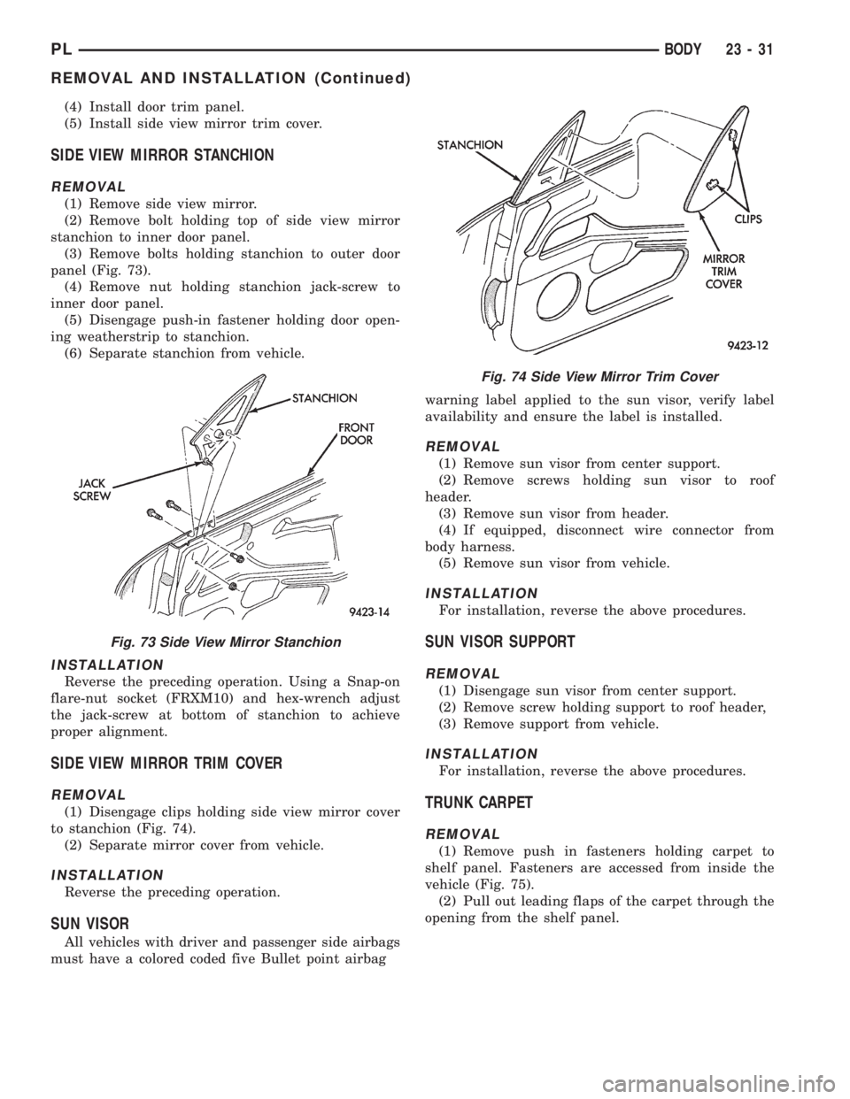
panel (Fig. 73).
(4) Remove nut holding stanchion jack-screw to
inner door panel.
(5) Disengage push-in fastener holding door open-
ing weatherstrip to stanchion.
(6) Separate stanchion from vehicle.
INSTALLATION
Reverse the preceding operation. Using a Snap-on
flare-nut socket (FRXM10) and hex-wrench adjust
the jack-screw at bottom of stanchion to achieve
proper alignment.
SIDE VIEW MIRROR TRIM COVER
REMOVAL
(1) Disengage clips holding side view mirror cover
to stanchion (Fig. 74).
(2) Separate mirror cover from vehicle.
INSTALLATION
Reverse the preceding operation.
SUN VISOR
All vehicles with driver and passenger side airbags
must have a colored coded five Bullet point airbagwarning label applied to the sun visor, verify label
availability and ensure the label is installed.
REMOVAL
(1) Remove sun visor from center support.
(2) Remove screws holding sun visor to roof
header.
(3) Remove sun visor from header.
(4) If equipped, disconnect wire connector from
body harness.
(5) Remove sun visor from vehicle.
INSTALLATION
For installation, reverse the above procedures.
SUN VISOR SUPPORT
REMOVAL
(1) Disengage sun visor from center support.
(2) Remove screw holding support to roof header,
(3) Remove support from vehicle.
INSTALLATION
For installation, reverse the above procedures.
TRUNK CARPET
REMOVAL
(1) Remove push in fasteners holding carpet to
shelf panel. Fasteners are accessed from inside the
vehicle (Fig. 75).
(2) Pull out leading flaps of the carpet through the
opening from the shelf panel.
Fig. 73 Side View Mirror Stanchion
Fig. 74 Side View Mirror Trim Cover
PLBODY 23 - 31
REMOVAL AND INSTALLATION (Continued)
Page 1114 of 1200
(7) Separate trunk lid from vehicle.
INSTALLATION
(1) Place trunk lid in position on vehicle.
(2) With aid from a helper, install bolts to hold bot-
tom of hinge to trunk lid.
(3) Install bolts to hold top of hinge to trunk lid.
(4) Align trunk lid to achieve equal spacing on all
sides and flush across gaps.
(5) Verify trunk lid operation and sealing.
(6) Connect wire connector and release cable on
latch.
(7) Install clips to hold wire harness and cable to
trunk lid.
TRUNK LID LIFT SPRINGS
REMOVAL
WARNING: USE EYE AND HAND PROTECTION
WHEN REMOVING SPRINGS, PERSONAL CAN
RESULT.
(1) Release trunk and open trunk lid.
(2) Support trunk lid on a suitable prop device.
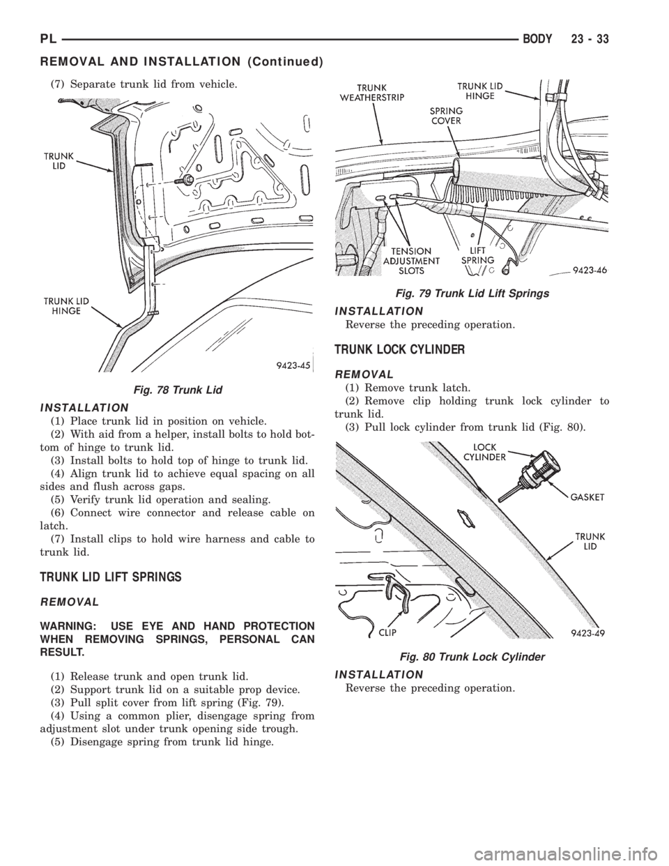
(3) Pull split cover from lift spring (Fig. 79).
(4) Using a common plier, disengage spring from
adjustment slot under trunk opening side trough.
(5) Disengage spring from trunk lid hinge.
INSTALLATION
Reverse the preceding operation.
TRUNK LOCK CYLINDER
REMOVAL
(1) Remove trunk latch.
(2) Remove clip holding trunk lock cylinder to
trunk lid.
(3) Pull lock cylinder from trunk lid (Fig. 80).
INSTALLATION
Reverse the preceding operation.
Fig. 78 Trunk Lid
Fig. 79 Trunk Lid Lift Springs
Fig. 80 Trunk Lock Cylinder
PLBODY 23 - 33
REMOVAL AND INSTALLATION (Continued)
Page 1124 of 1200
STATIONARY GLASS
INDEX
page page
DESCRIPTION AND OPERATION
SAFETY PRECAUTIONS.................. 43
REMOVAL AND INSTALLATION
QUARTER GLASS....................... 45REAR WINDOW......................... 46
WINDSHIELD........................... 43
DESCRIPTION AND OPERATION
SAFETY PRECAUTIONS
WARNING: DO NOT OPERATE THE VEHICLE
WITHIN 24 HOURS OF WINDSHIELD INSTALLATION.
IT TAKES AT LEAST 24 HOURS FOR URETHANE
ADHESIVE TO CURE. IF IT IS NOT CURED, THE
WINDSHIELD MAY NOT PERFORM PROPERLY IN
AN ACCIDENT.
URETHANE ADHESIVES ARE APPLIED AS A SYS-
TEM. USE GLASS CLEANER, GLASS PREP SOL-
VENT, GLASS PRIMER, PVC (VINYL) PRIMER AND
PINCHWELD (FENCE) PRIMER PROVIDED BY THE
ADHESIVE MANUFACTURER. IF NOT, STRUCTURAL
INTEGRITY COULD BE COMPROMISED.
CHRYSLER DOES NOT RECOMMEND GLASS
ADHESIVE BY BRAND. TECHNICIANS SHOULD
REVIEW PRODUCT LABELS AND TECHNICAL DATA
SHEETS, AND USE ONLY ADHESIVES THAT THEIR
MANUFACTURES WARRANT WILL RESTORE A
VEHICLE TO THE REQUIREMENTS OF FMVSS 212.
TECHNICIANS SHOULD ALSO INSURE THAT PRIM-
ERS AND CLEANERS ARE COMPATIBLE WITH THE
PARTICULAR ADHESIVE USED.
BE SURE TO REFER TO THE URETHANE MANU-
FACTURER'S DIRECTIONS FOR CURING TIME
SPECIFICATIONS, AND DO NOT USE ADHESIVE
AFTER ITS EXPIRATION DATE.
VAPORS THAT ARE EMITTED FROM THE URE-
THANE ADHESIVE OR PRIMER COULD CAUSE
PERSONAL INJURY. USE THEM IN A WELL-VENTI-
LATED AREA.
SKIN CONTACT WITH URETHANE ADHESIVE
SHOULD BE AVOIDED. PERSONAL INJURY MAY
RESULT.
ALWAYS WEAR EYE AND HAND PROTECTION
WHEN WORKING WITH GLASS.CAUTION: Protect all painted and trimmed surfaces
from coming in contact with urethane or primers.
Be careful not to damage painted surfaces when
removing moldings or cutting urethane around
windshield.
It is difficult to salvage a windshield during the
removal operation. The windshield is part of the
structural support for the roof. The urethane bonding
used to secure the windshield to the fence is difficult
to cut or clean from any surface. If the moldings are
set in urethane, it would also be unlikely they could
be salvaged. Before removing the windshield, check
the availability of the windshield and moldings from
the parts supplier.
REMOVAL AND INSTALLATION
WINDSHIELD
The urethane adhesive holding the windshield to
the opening pinch weld (fence) can be cut using a
sharp cold knife from the exterior of the vehicle.
Using the cold knife method is effective if the wind-
shield is already broken. If the glass must be sal-
vaged, cutting the urethane adhesive from the
interior of the vehicle using a reciprocating or oscil-
lating power knife is recommended.
WINDSHIELD REMOVAL ± EXTERIOR METHOD
(1) Remove inside rear view mirror.
(2) Remove windshield wiper arms.
(3) Remove cowl cover.
(4) Place protective covers over instrument panel
and hood.
PLBODY 23 - 43