1999 DODGE NEON warning
[x] Cancel search: warningPage 721 of 1200

cause of low compression unless some malfunc-
tion is present.
(11) Clean or replace spark plugs as necessary
and adjust gap as specified in Group 8, Electrical.
Tighten to specifications.
(12) Test resistance of spark plug cables. Refer to
Group 8, Electrical Ignition System Secondary Cir-
cuit Inspection.
(13) Test coil output voltage, primary and second-
ary resistance. Replace parts as necessary. Refer to
Group 8, Electrical Ignition System.
(14) Check fuel pump pressure at idle and differ-
ent RPM ranges. Refer to Group 14, Fuel System for
Specifications.
(15) The air filter elements should be replaced as
specified in Group 0, Lubrication and Maintenance,.
(16) Inspect crankcase ventilation system as out
lined in Group 0, Lubrication and Maintenance. For
emission controls see Group 25, Emission Controls
for service procedures.
(17) Inspect and adjust accessory belt drives refer-
ring to Group 7, Cooling System, Accessory Drive
Belts for proper adjustments.
(18) Road test vehicle as a final test.
CYLINDER COMBUSTION PRESSURE LEAKAGE
TEST
The combustion pressure leakage test provides an
accurate means for determining engine condition.
Combustion pressure leakage testing will detect:
²Exhaust and intake valve leaks (improper seat-
ing).
²Leaks between adjacent cylinders or into water
jacket.
²Any causes for combustion/compression pressure
loss.
WARNING: DO NOT REMOVE THE RADIATOR CAP
WITH THE SYSTEM HOT AND UNDER PRESSURE
BECAUSE SERIOUS BURNS FROM COOLANT CAN
OCCUR.
Check the coolant level and fill as required. DO
NOT install the radiator cap.
Start and operate the engine until it attains nor-
mal operating temperature, then turn the engine
OFF.
Clean spark plug recesses with compressed air.
Remove the spark plugs.
Remove the oil filler cap.
Remove the air cleaner.
Calibrate the tester according to the manufactur-
er's instructions. The shop air source for testing
should maintain 483 kPa (70 psi) minimum, 1 379
kPa (200 psi) maximum and 552 kPa (80 psi) recom-
mended.Perform the test procedures on each cylinder
according to the tester manufacturer's instructions.
While testing, listen for pressurized air escaping
through the throttle body, tailpipe and oil filler cap
opening. Check for bubbles in the radiator coolant.
All gauge pressure indications should be equal,
with no more than 25% leakage.
FOR EXAMPLE:At 552 kPa (80 psi) input pres-
sure, a minimum of 414 kPa (60 psi) should be main-
tained in the cylinder.
LASH ADJUSTER (TAPPET) NOISE DIAGNOSIS
A tappet-like noise may be produced from several
items. Check the following items.
(1) Engine oil level too high or too low. This may
cause aerated oil to enter the adjusters and cause
them to be spongy.
(2) Insufficient running time after rebuilding cylin-
der head. Low speed running up to 1 hour may be
required.
(3) During this time, turn engine off and let set for
a few minutes before restarting. Repeat this several
times after engine has reached normal operating
temperature.
(4) Low oil pressure.
(5) The oil restrictor pressed into the vertical oil
passage to the cylinder head is plugged with debris.
(6) Air ingested into oil due to broken or cracked
oil pump pick up.
(7) Worn valve guides.
(8) Rocker arm ears contacting valve spring
retainer.
(9) Rocker arm loose, adjuster stuck or at maxi-
mum extension and still leaves lash in the system.
(10) Faulty lash adjuster.
a. Check lash adjusters for sponginess while
installed in cylinder head. Depress part of rocker
arm over adjuster. Normal adjusters should feel very
firm. Spongy adjusters can be bottomed out easily.
b. Remove suspected rocker arms (sohc) or lash
adjuster (dohc) and replace.
INSPECTION (ENGINE OIL LEAKS IN GENERAL)
Begin with a through visual inspection of the
engine, particularly at the area of the suspected leak.
If an oil leak source is not readily identifiable, the
following steps should be followed:
(1) Do not clean or degrease the engine at this
time because some solvents may cause rubber to
swell, temporarily stopping the leak.
(2) Add an oil soluble dye (use as recommended by
manufacturer). Start the engine and let idle for
approximately 15 minutes. Check the oil dipstick to
make sure the dye is thoroughly mixed as indicated
with a bright yellow color under a black light.
9 - 8 ENGINEPL
DIAGNOSIS AND TESTING (Continued)
Page 821 of 1200
NOTE: When replacement is required on any com-
ponent of the exhaust system, you must use origi-
nal equipment parts (or their equivalent).
INSTALLATION
When assembling exhaust systemdo nottighten
clamps until components are aligned and clearances
are checked.
(1) Assemble catalytic convertor to exhaust mani-
fold connection. Use a new flange gasket (LEV only)
(Fig. 9) or (Fig. 10).
(2) Assemble exhaust pipe to catalytic convertor
and the support to the underbody
(3) Install the muffler to exhaust pipe and the sup-
ports to the underbody.
(4) Working from the front of system;
(5) Align and tighten the catalytic convertor to
exhaust manifold ball joint bolts to 27 N´m (20 ft.
lbs.) (Fig. 9) or flex-joint attaching nuts (LEV) to 28
N´m (250 in. lbs.).
(6) Align each component to maintain position and
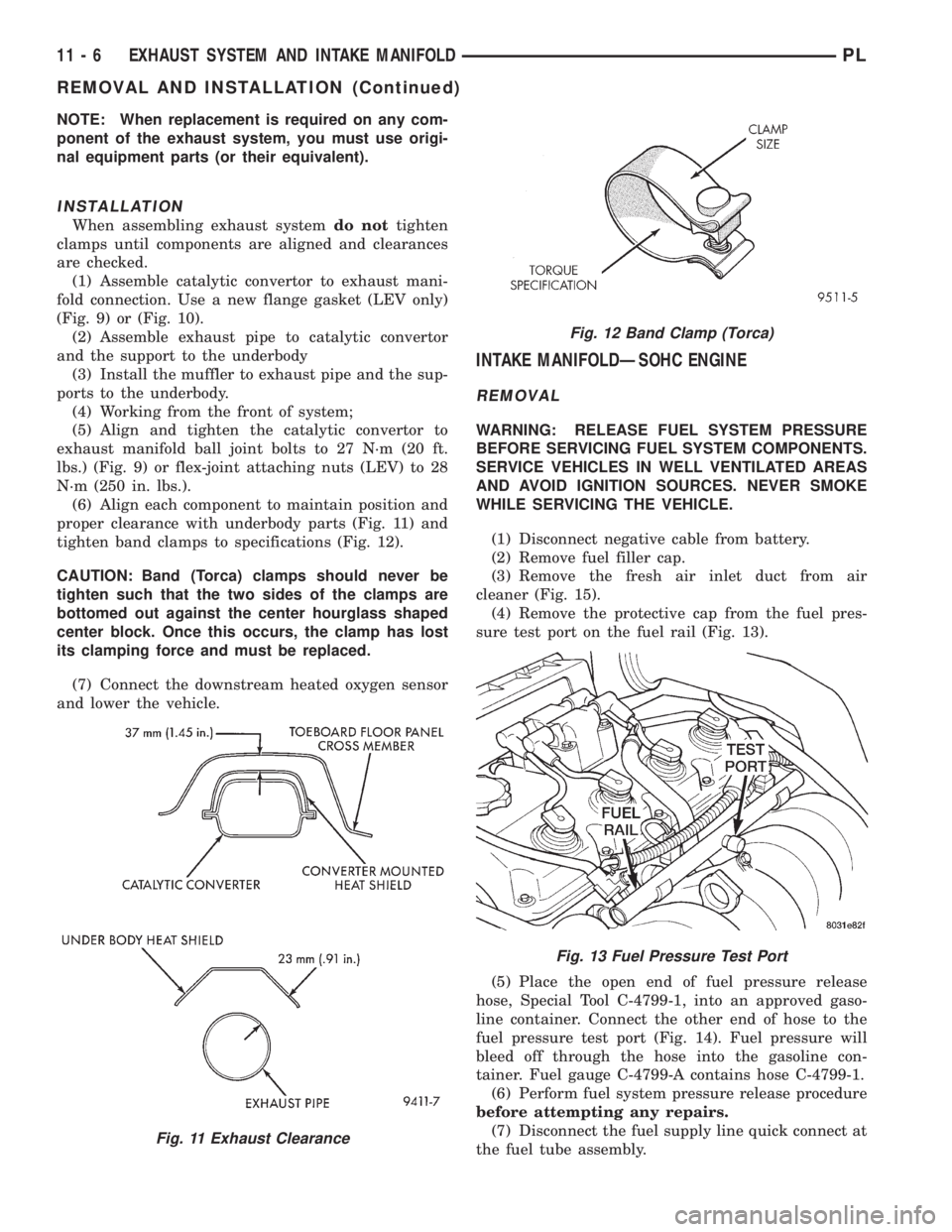
proper clearance with underbody parts (Fig. 11) and
tighten band clamps to specifications (Fig. 12).
CAUTION: Band (Torca) clamps should never be
tighten such that the two sides of the clamps are
bottomed out against the center hourglass shaped
center block. Once this occurs, the clamp has lost
its clamping force and must be replaced.
(7) Connect the downstream heated oxygen sensor
and lower the vehicle.
INTAKE MANIFOLDÐSOHC ENGINE
REMOVAL
WARNING: RELEASE FUEL SYSTEM PRESSURE
BEFORE SERVICING FUEL SYSTEM COMPONENTS.
SERVICE VEHICLES IN WELL VENTILATED AREAS
AND AVOID IGNITION SOURCES. NEVER SMOKE
WHILE SERVICING THE VEHICLE.
(1) Disconnect negative cable from battery.
(2) Remove fuel filler cap.
(3) Remove the fresh air inlet duct from air
cleaner (Fig. 15).
(4) Remove the protective cap from the fuel pres-
sure test port on the fuel rail (Fig. 13).
(5) Place the open end of fuel pressure release
hose, Special Tool C-4799-1, into an approved gaso-
line container. Connect the other end of hose to the
fuel pressure test port (Fig. 14). Fuel pressure will
bleed off through the hose into the gasoline con-
tainer. Fuel gauge C-4799-A contains hose C-4799-1.
(6) Perform fuel system pressure release procedure
before attempting any repairs.
(7) Disconnect the fuel supply line quick connect at
the fuel tube assembly.
Fig. 11 Exhaust Clearance
Fig. 12 Band Clamp (Torca)
Fig. 13 Fuel Pressure Test Port
11 - 6 EXHAUST SYSTEM AND INTAKE MANIFOLDPL
REMOVAL AND INSTALLATION (Continued)
Page 822 of 1200
WARNING: WRAP SHOP TOWELS AROUND HOSE
TO CATCH ANY GASOLINE SPILLAGE.
(8) Remove fuel rail assembly attaching screws
and remove fuel rail assembly from engine. Cover
injector holes with suitable covering.
CAUTION: Do not set fuel injectors on their tips,
damage may occur to the injectors
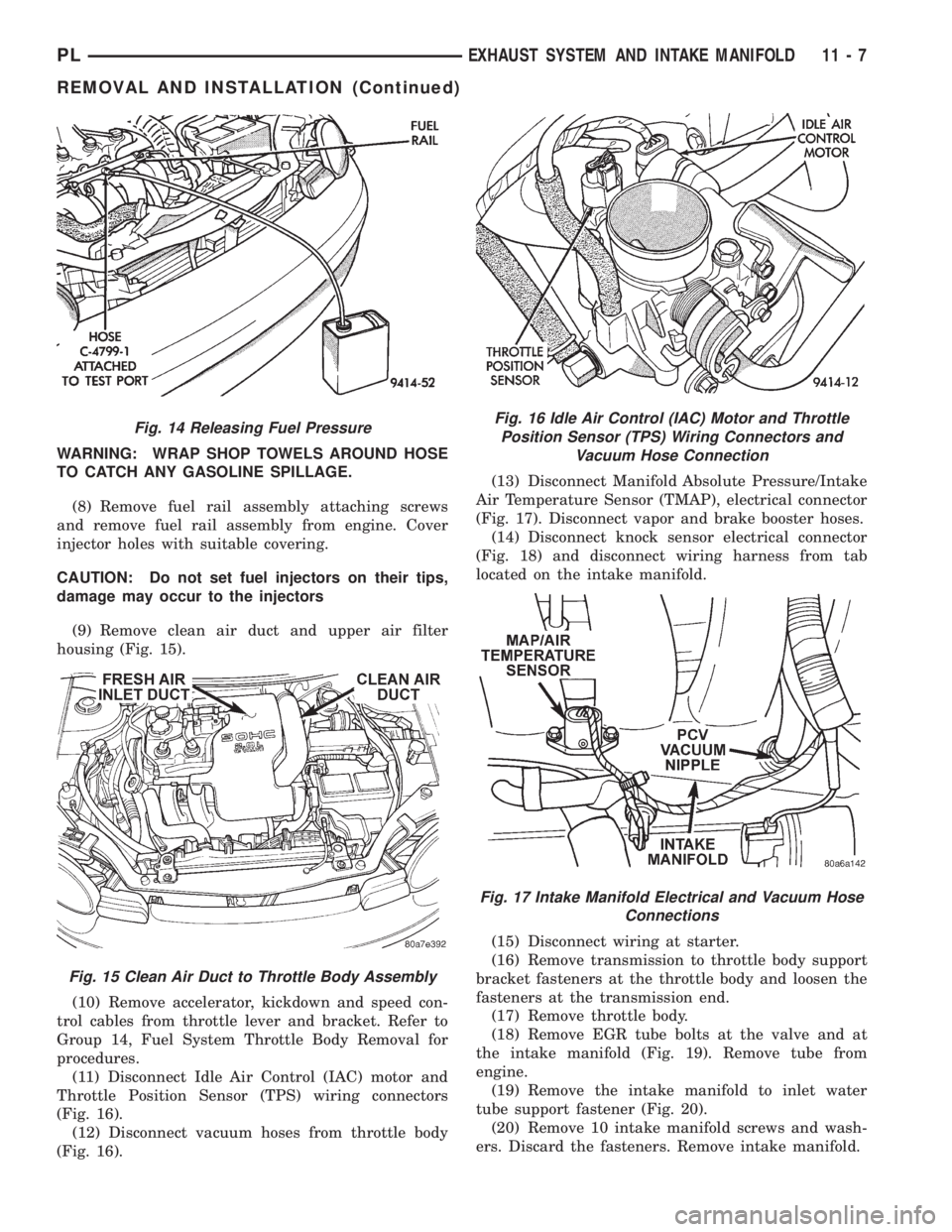
(9) Remove clean air duct and upper air filter
housing (Fig. 15).
(10) Remove accelerator, kickdown and speed con-
trol cables from throttle lever and bracket. Refer to
Group 14, Fuel System Throttle Body Removal for
procedures.
(11) Disconnect Idle Air Control (IAC) motor and
Throttle Position Sensor (TPS) wiring connectors
(Fig. 16).
(12) Disconnect vacuum hoses from throttle body
(Fig. 16).(13) Disconnect Manifold Absolute Pressure/Intake
Air Temperature Sensor (TMAP), electrical connector
(Fig. 17). Disconnect vapor and brake booster hoses.
(14) Disconnect knock sensor electrical connector
(Fig. 18) and disconnect wiring harness from tab
located on the intake manifold.
(15) Disconnect wiring at starter.
(16) Remove transmission to throttle body support
bracket fasteners at the throttle body and loosen the
fasteners at the transmission end.
(17) Remove throttle body.
(18) Remove EGR tube bolts at the valve and at
the intake manifold (Fig. 19). Remove tube from
engine.
(19) Remove the intake manifold to inlet water
tube support fastener (Fig. 20).
(20) Remove 10 intake manifold screws and wash-
ers. Discard the fasteners. Remove intake manifold.
Fig. 14 Releasing Fuel Pressure
Fig. 15 Clean Air Duct to Throttle Body Assembly
Fig. 16 Idle Air Control (IAC) Motor and Throttle
Position Sensor (TPS) Wiring Connectors and
Vacuum Hose Connection
Fig. 17 Intake Manifold Electrical and Vacuum Hose
Connections
PLEXHAUST SYSTEM AND INTAKE MANIFOLD 11 - 7
REMOVAL AND INSTALLATION (Continued)
Page 824 of 1200

INTAKE MANIFOLDÐDOHC ENGINE
REMOVAL
WARNING: RELEASE FUEL SYSTEM PRESSURE
BEFORE SERVICING FUEL SYSTEM COMPONENTS.
SERVICE VEHICLES IN WELL VENTILATED AREAS
AND AVOID IGNITION SOURCES. NEVER SMOKE
WHILE SERVICING THE VEHICLE.
(1) Disconnect negative cable from battery.
(2) Remove fuel filler cap.
(3) Loosen wing nut on intake and remove fresh
air inlet duct (Fig. 23).
(4) Remove the protective cap from the fuel pres-
sure test port on the fuel rail (Fig. 21).
(5) Place the open end of fuel pressure release
hose, Special Tool C-4799-1, into an approved gaso-
line container. Connect the other end of hose to the
fuel pressure test port (Fig. 22). Fuel pressure will
bleed off through the hose into the gasoline con-
tainer. Fuel gauge C-4799-A contains hose C-4799-1.
(6) Disconnect the fuel supply line quick-connect at
the fuel tube assembly.
(7) Remove clean air inlet duct.WARNING: WRAP SHOP TOWELS AROUND HOSE
TO CATCH ANY GASOLINE SPILLAGE.
(8) Disconnect the coolant temperature sensor
(Fig. 24).
(9) Disconnect heater hose from intake manifold.
(10) Disconnect heater tube from bottom of intake
manifold.
(11) Disconnect upper radiator hose and coolant
recovery hose.
(12) Remove fuel rail assembly attaching screws
and remove fuel rail assembly from engine. Cover
injector holes with suitable covering.
CAUTION: Do not set fuel injectors on their tips,
damage may occur to the injectors
Fig. 21 Fuel Pressure Test PortÐTypical
Fig. 22 Releasing Fuel PressureÐTypical
Fig. 23 Fresh Air Inlet Duct
Fig. 24 Engine Coolant Temperature Sensor
PLEXHAUST SYSTEM AND INTAKE MANIFOLD 11 - 9
REMOVAL AND INSTALLATION (Continued)
Page 832 of 1200
FRAMES
INDEX
page page
REMOVAL AND INSTALLATION
FRONT SUSPENSION CROSSMEMBER....... 3
SPECIFICATIONS
STRUCTURAL DIMENSIONS................ 4TORQUE SPECIFICATIONS................ 10
REMOVAL AND INSTALLATION
FRONT SUSPENSION CROSSMEMBER
WARNING: IF SUSPENSION CROSSMEMBER IS
REPLACED DUE TO COLLISION DAMAGE, INSPECT
THE STEERING COLUMN TO STEERING GEAR
COUPLING FOR DAMAGE. REFER TO GROUP 19,
STEERING FOR INSTRUCTIONS.
Before removing front suspension crossmem-
ber, index mark location of crossmember on
frame to aid installation.
The front suspension crossmember must be prop-
erly installed to achieve design camber, caster set-
tings and wheel stagger. The crossmember can be
installed out of position on the frame rails due to its
design. Bolts and cage nuts hold the rear of the
crossmember to the frame torque boxes. Bolts and
J-nuts hold the front of the crossmember to the
frame rails. No designed in locating device is used to
position the crossmember in the vehicle. Before
removing the crossmember mark the frame torque
box around the rear mounting location to aid instal-
lation. A crossmember that is removed during service
must be installed in the same position from which it
was removed. To verify that crossmember is in the
proper position, refer to the dimensions provided.
Front end dimensions are gauged from the principal
locating point (PLP) holes located under the frame
torque boxes rearward of the front wheels. After
removal and installation of the crossmember is per-
formed, verify that front suspension alignment is
within specifications. If camber, caster settings and
wheel stagger is not within specifications, loosen and
reposition crossmember to bring suspension within
specifications. Refer to Group 2, Front Suspension
and Driveshaft for additional information.
REMOVAL
(1) Hoist and support vehicle on safety stands.
(2) Using a suitable marking device, mark the out-
line of the suspension crossmember on the frame
torque box around the rear mounting location.(3) Remove front wheels from vehicle.
(4) Remove pinch bolts holding front ball joints to
spindles.
(5) Separate ball joints from spindles.
(6) Position a suitable lifting device under the
crossmember.
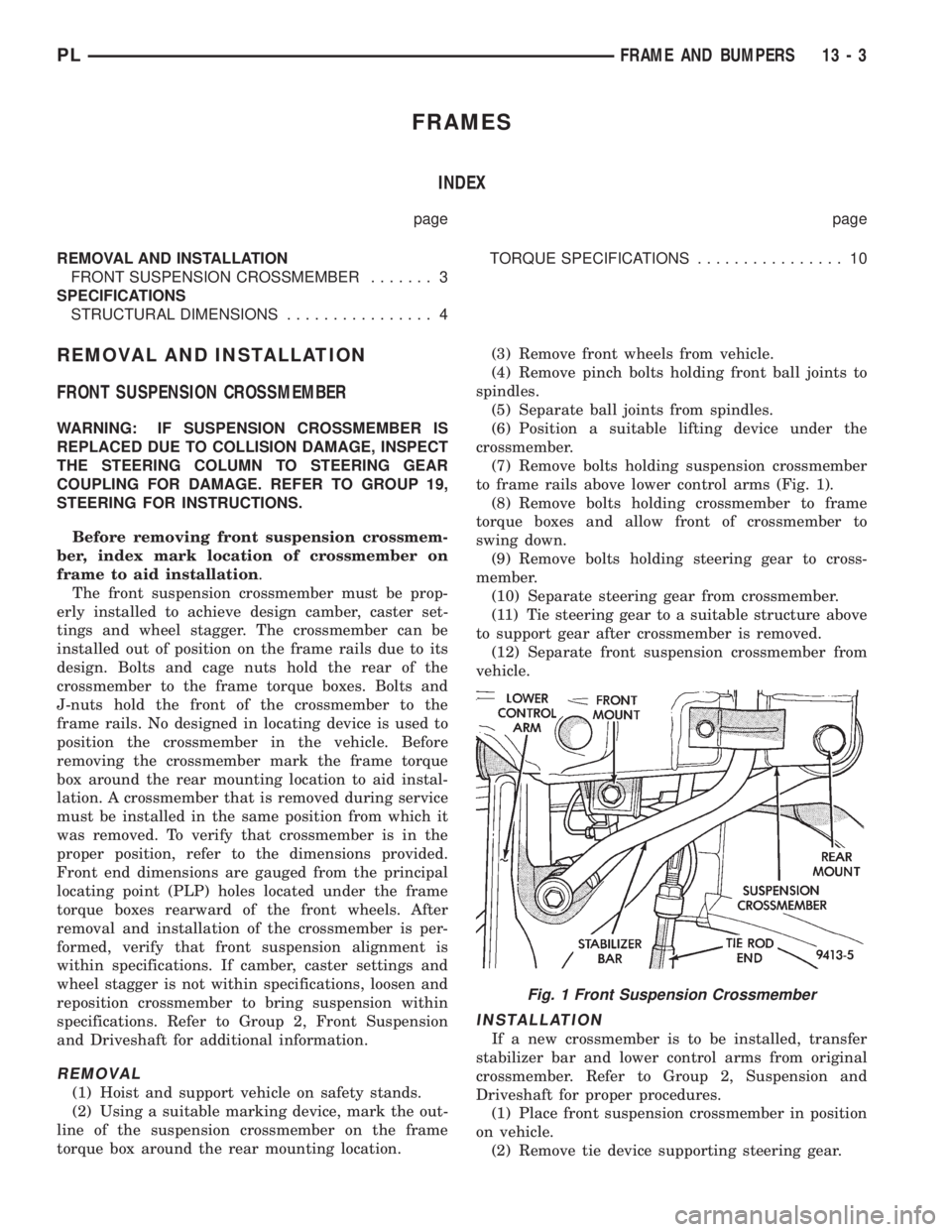
(7) Remove bolts holding suspension crossmember
to frame rails above lower control arms (Fig. 1).
(8) Remove bolts holding crossmember to frame
torque boxes and allow front of crossmember to
swing down.
(9) Remove bolts holding steering gear to cross-
member.
(10) Separate steering gear from crossmember.
(11) Tie steering gear to a suitable structure above
to support gear after crossmember is removed.
(12) Separate front suspension crossmember from
vehicle.
INSTALLATION
If a new crossmember is to be installed, transfer
stabilizer bar and lower control arms from original
crossmember. Refer to Group 2, Suspension and
Driveshaft for proper procedures.
(1) Place front suspension crossmember in position
on vehicle.
(2) Remove tie device supporting steering gear.
Fig. 1 Front Suspension Crossmember
PLFRAME AND BUMPERS 13 - 3
Page 846 of 1200
FUEL INJECTORS
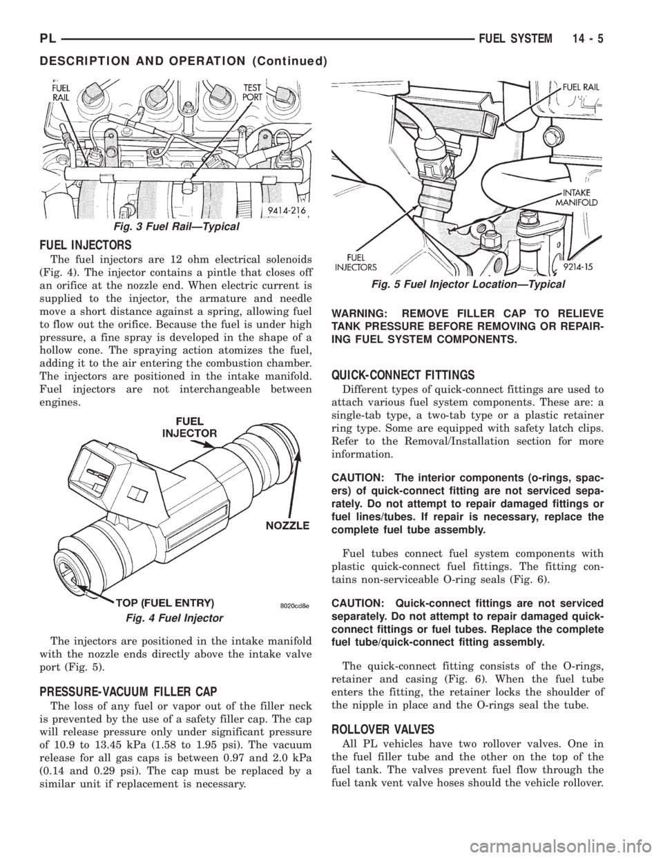
The fuel injectors are 12 ohm electrical solenoids
(Fig. 4). The injector contains a pintle that closes off
an orifice at the nozzle end. When electric current is
supplied to the injector, the armature and needle
move a short distance against a spring, allowing fuel
to flow out the orifice. Because the fuel is under high
pressure, a fine spray is developed in the shape of a
hollow cone. The spraying action atomizes the fuel,
adding it to the air entering the combustion chamber.
The injectors are positioned in the intake manifold.
Fuel injectors are not interchangeable between
engines.
The injectors are positioned in the intake manifold
with the nozzle ends directly above the intake valve
port (Fig. 5).
PRESSURE-VACUUM FILLER CAP
The loss of any fuel or vapor out of the filler neck
is prevented by the use of a safety filler cap. The cap
will release pressure only under significant pressure
of 10.9 to 13.45 kPa (1.58 to 1.95 psi). The vacuum
release for all gas caps is between 0.97 and 2.0 kPa
(0.14 and 0.29 psi). The cap must be replaced by a
similar unit if replacement is necessary.WARNING: REMOVE FILLER CAP TO RELIEVE
TANK PRESSURE BEFORE REMOVING OR REPAIR-
ING FUEL SYSTEM COMPONENTS.
QUICK-CONNECT FITTINGS
Different types of quick-connect fittings are used to
attach various fuel system components. These are: a
single-tab type, a two-tab type or a plastic retainer
ring type. Some are equipped with safety latch clips.
Refer to the Removal/Installation section for more
information.
CAUTION: The interior components (o-rings, spac-
ers) of quick-connect fitting are not serviced sepa-
rately. Do not attempt to repair damaged fittings or
fuel lines/tubes. If repair is necessary, replace the
complete fuel tube assembly.
Fuel tubes connect fuel system components with
plastic quick-connect fuel fittings. The fitting con-
tains non-serviceable O-ring seals (Fig. 6).
CAUTION: Quick-connect fittings are not serviced
separately. Do not attempt to repair damaged quick-
connect fittings or fuel tubes. Replace the complete
fuel tube/quick-connect fitting assembly.
The quick-connect fitting consists of the O-rings,
retainer and casing (Fig. 6). When the fuel tube
enters the fitting, the retainer locks the shoulder of
the nipple in place and the O-rings seal the tube.
ROLLOVER VALVES
All PL vehicles have two rollover valves. One in
the fuel filler tube and the other on the top of the
fuel tank. The valves prevent fuel flow through the
fuel tank vent valve hoses should the vehicle rollover.
Fig. 3 Fuel RailÐTypical
Fig. 4 Fuel Injector
Fig. 5 Fuel Injector LocationÐTypical
PLFUEL SYSTEM 14 - 5
DESCRIPTION AND OPERATION (Continued)
Page 851 of 1200
SERVICE PROCEDURES
FUEL SYSTEM PRESSURE RELEASE PROCEDURE
WARNING: RELEASE FUEL SYSTEM PRESSURE
BEFORE SERVICING FUEL SYSTEM COMPONENTS.
SERVICE VEHICLES IN WELL VENTILATED AREAS
AND AVOID IGNITION SOURCES. NEVER SMOKE
WHILE SERVICING THE VEHICLE.
(1) Disconnect negative cable from battery.
(2) Remove fuel filler cap.
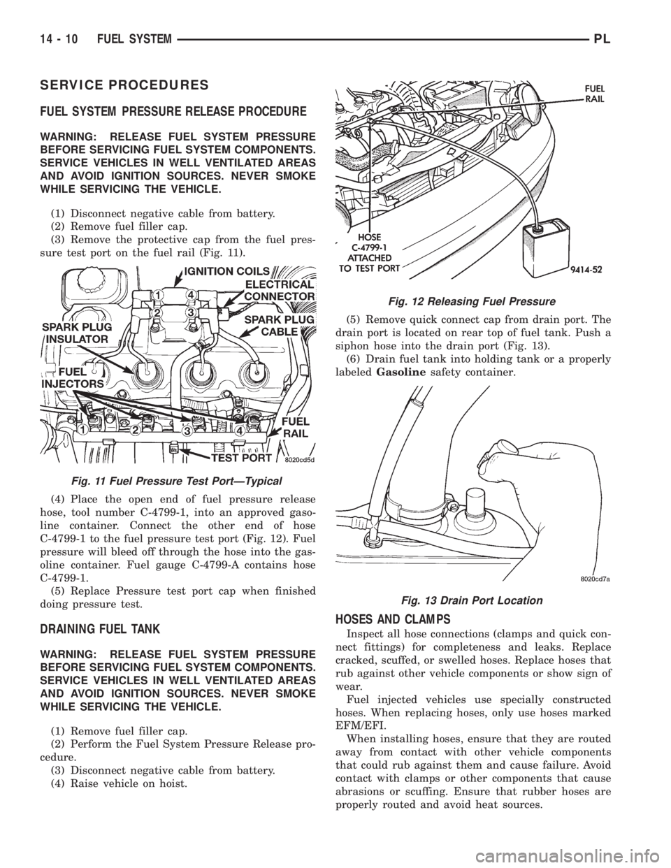
(3) Remove the protective cap from the fuel pres-
sure test port on the fuel rail (Fig. 11).
(4) Place the open end of fuel pressure release
hose, tool number C-4799-1, into an approved gaso-
line container. Connect the other end of hose
C-4799-1 to the fuel pressure test port (Fig. 12). Fuel
pressure will bleed off through the hose into the gas-
oline container. Fuel gauge C-4799-A contains hose
C-4799-1.
(5) Replace Pressure test port cap when finished
doing pressure test.
DRAINING FUEL TANK
WARNING: RELEASE FUEL SYSTEM PRESSURE
BEFORE SERVICING FUEL SYSTEM COMPONENTS.
SERVICE VEHICLES IN WELL VENTILATED AREAS
AND AVOID IGNITION SOURCES. NEVER SMOKE
WHILE SERVICING THE VEHICLE.
(1) Remove fuel filler cap.
(2) Perform the Fuel System Pressure Release pro-
cedure.
(3) Disconnect negative cable from battery.
(4) Raise vehicle on hoist.(5) Remove quick connect cap from drain port. The
drain port is located on rear top of fuel tank. Push a
siphon hose into the drain port (Fig. 13).
(6) Drain fuel tank into holding tank or a properly
labeledGasolinesafety container.
HOSES AND CLAMPS
Inspect all hose connections (clamps and quick con-
nect fittings) for completeness and leaks. Replace
cracked, scuffed, or swelled hoses. Replace hoses that
rub against other vehicle components or show sign of
wear.
Fuel injected vehicles use specially constructed
hoses. When replacing hoses, only use hoses marked
EFM/EFI.
When installing hoses, ensure that they are routed
away from contact with other vehicle components
that could rub against them and cause failure. Avoid
contact with clamps or other components that cause
abrasions or scuffing. Ensure that rubber hoses are
properly routed and avoid heat sources.
Fig. 11 Fuel Pressure Test PortÐTypical
Fig. 12 Releasing Fuel Pressure
Fig. 13 Drain Port Location
14 - 10 FUEL SYSTEMPL
Page 852 of 1200
The hose clamps have rolled edges to prevent the
clamp from cutting into the hose. Only use clamps
that are original equipment or equivalent. Other
types of clamps may cut into the hoses and cause
high pressure fuel leaks. Tighten hose clamps to 1
N´m (10 in. lbs.) torque.
QUICK-CONNECT FITTINGS
REMOVAL
When disconnecting a quick-connect fitting, the
retainer will remain on the fuel tube nipple.
WARNING: RELEASE FUEL SYSTEM PRESSURE
BEFORE DISCONNECTING A QUICK-CONNECT FIT-
TINGS. REFER TO THE FUEL PRESSURE RELEASE
PROCEDURE.
(1) Disconnect negative cable from battery.
(2) Perform Fuel Pressure Release Procedure.
Refer to the Fuel Pressure Release Procedure in this
section.
(3) Squeeze retainer tabs together and pull fuel
tube/quick-connect fitting assembly off of fuel tube
nipple. The retainer will remain on fuel tube.
INSTALLATION
CAUTION: Never install a quick-connect fitting
without the retainer being either on the fuel tube or
already in the quick-connect fitting. In either case,
ensure the retainer locks securely into the quick-
connect fitting by firmly pulling on fuel tube and fit-
ting to ensure it is secured.
(1) Using a clean lint free cloth, clean the fuel tube
nipple and retainer.
(2) Prior to connecting the fitting to the fuel tube,
coat the fuel tube nipple with clean 30 weight engine
oil.
(3) Push the quick-connect fitting over the fuel
tube until theretainer seats and a click is heard.
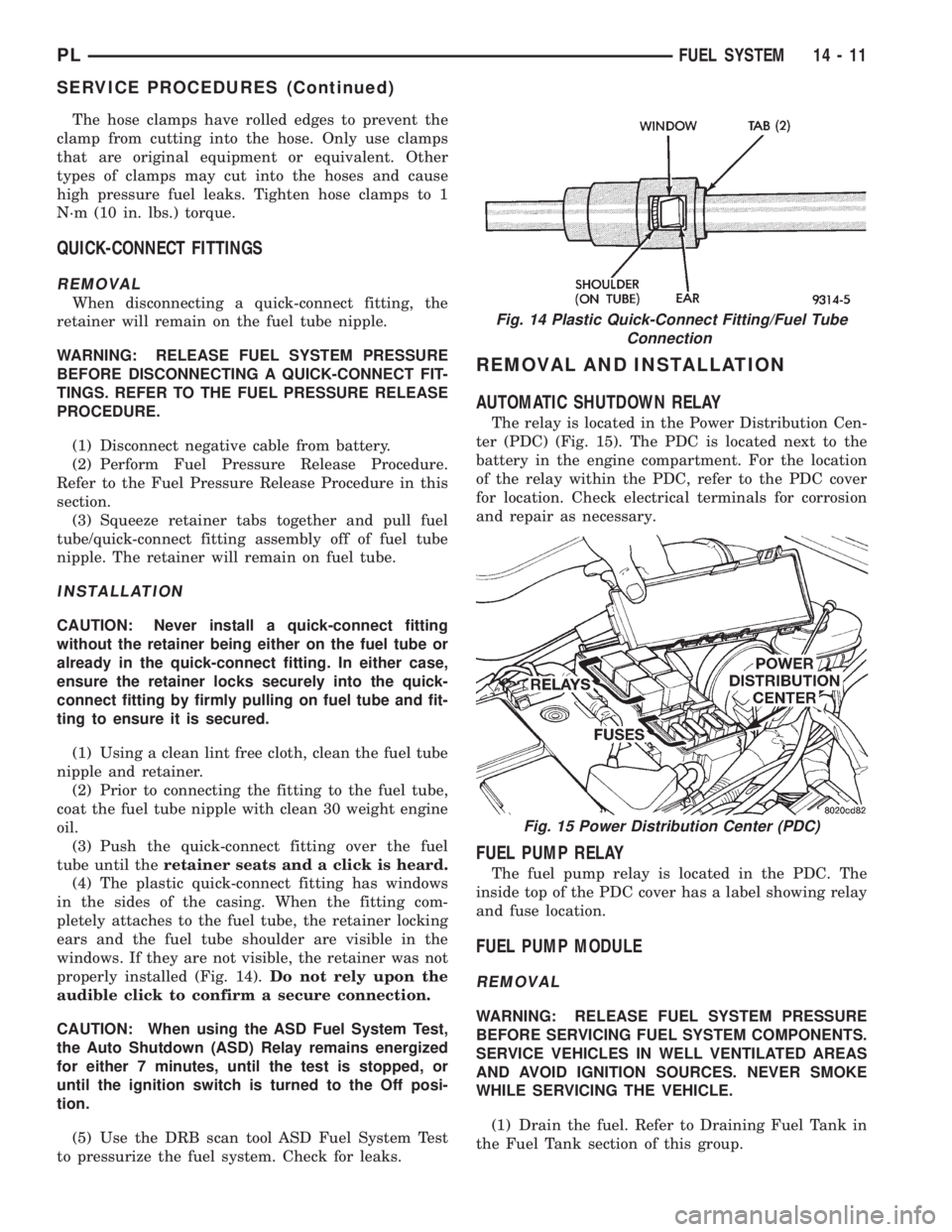
(4) The plastic quick-connect fitting has windows
in the sides of the casing. When the fitting com-
pletely attaches to the fuel tube, the retainer locking
ears and the fuel tube shoulder are visible in the
windows. If they are not visible, the retainer was not
properly installed (Fig. 14).Do not rely upon the
audible click to confirm a secure connection.
CAUTION: When using the ASD Fuel System Test,
the Auto Shutdown (ASD) Relay remains energized
for either 7 minutes, until the test is stopped, or
until the ignition switch is turned to the Off posi-
tion.
(5) Use the DRB scan tool ASD Fuel System Test
to pressurize the fuel system. Check for leaks.
REMOVAL AND INSTALLATION
AUTOMATIC SHUTDOWN RELAY
The relay is located in the Power Distribution Cen-
ter (PDC) (Fig. 15). The PDC is located next to the
battery in the engine compartment. For the location
of the relay within the PDC, refer to the PDC cover
for location. Check electrical terminals for corrosion
and repair as necessary.
FUEL PUMP RELAY
The fuel pump relay is located in the PDC. The
inside top of the PDC cover has a label showing relay
and fuse location.
FUEL PUMP MODULE
REMOVAL
WARNING: RELEASE FUEL SYSTEM PRESSURE
BEFORE SERVICING FUEL SYSTEM COMPONENTS.
SERVICE VEHICLES IN WELL VENTILATED AREAS
AND AVOID IGNITION SOURCES. NEVER SMOKE
WHILE SERVICING THE VEHICLE.
(1) Drain the fuel. Refer to Draining Fuel Tank in
the Fuel Tank section of this group.
Fig. 14 Plastic Quick-Connect Fitting/Fuel Tube
Connection
Fig. 15 Power Distribution Center (PDC)
PLFUEL SYSTEM 14 - 11
SERVICE PROCEDURES (Continued)