1999 DODGE NEON warning
[x] Cancel search: warningPage 298 of 1200
VEHICLE SPEED CONTROL SYSTEM
CONTENTS
page page
GENERAL INFORMATION
INTRODUCTION......................... 1
DESCRIPTION AND OPERATION
POWERTRAIN CONTROL MODULE.......... 3
SERVO CABLE.......................... 3
SPEED CONTROL SERVO.................. 1
SPEED CONTROL SWITCHES.............. 2
STOP LAMP SWITCH..................... 3
VACUUM RESERVOIR.................... 3
VEHICLE SPEED AND DISTANCE............ 3
DIAGNOSIS AND TESTING
CHECKING FOR DIAGNOSTIC CODES........ 4
ELECTRICAL TESTS AT POWERTRAIN
CONTROL MODULE..................... 7
OVERSHOOT/UNDERSHOOT FOLLOWING
SPEED CONTROL SET................... 6ROAD TEST............................ 3
SERVO VACUUM TEST.................... 6
SPEED CONTROL ELECTRICAL TEST........ 4
SPEED CONTROL SWITCH TEST............ 6
STOP LAMP SWITCH TEST................ 6
VACUUM SUPPLY TEST................... 8
VEHICLE SPEED SENSOR................. 8
REMOVAL AND INSTALLATION
POWERTRAIN CONTROL MODULE......... 10
SPEED CONTROL SERVO CABLE............ 9
SPEED CONTROL SERVO.................. 8
SPEED CONTROL SWITCH................. 8
STOP LAMP SWITCH.................... 8
VACUUM RESERVOIR................... 10
VEHICLE SPEED SENSOR................ 10
GENERAL INFORMATION
INTRODUCTION
The speed control system is electronically con-
trolled and vacuum operated. The electronic control
is integrated into the powertrain control module
which is located in the engine compartment. The con-
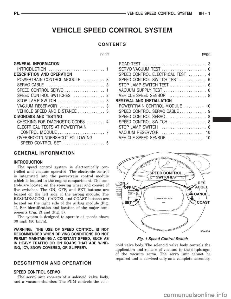
trols are located on the steering wheel and consist of
five switches. The ON, OFF, and SET buttons are
located on the left side of the airbag module. The
RESUME/ACCEL, CANCEL and COAST buttons are
located on the right side of the airbag module (Fig.
1). For identification and location of the major com-
ponents (Fig. 2) and (Fig. 3).
The system is designed to operate at speeds above
30 mph (50 km/h).
WARNING: THE USE OF SPEED CONTROL IS NOT
RECOMMENDED WHEN DRIVING CONDITIONS DO NOT
PERMIT MAINTAINING A CONSTANT SPEED, SUCH AS
IN HEAVY TRAFFIC OR ON ROADS THAT ARE WIND-
ING, ICY, SNOW COVERED, OR SLIPPERY.
DESCRIPTION AND OPERATION
SPEED CONTROL SERVO
The servo unit consists of a solenoid valve body,
and a vacuum chamber. The PCM controls the sole-noid valve body. The solenoid valve body controls the
application and release of vacuum to the diaphragm
of the vacuum servo. The servo unit cannot be
repaired and is serviced only as a complete assembly.
Fig. 1 Speed Control Switch
PLVEHICLE SPEED CONTROL SYSTEM 8H - 1
Page 305 of 1200
(c) If continuity is OK between cavity 62 and
cavity 1, repair open circuit between cavity 2 of the
stop lamp switch connector and ground.
(6) Using an ohmmeter, check continuity from cav-
ity 76 on PCM connector to ground with the trans-
mission in park or neutral. If no continuity, test TRS/
Park-Neutral switch and switch wiring
(7) Turn speed control and ignition switch OFF.
(8) Unplug the BLACK 40-way connector from the
Powertrain Control Module (PCM)
(9) Using an ohmmeter, check continuity from cav-
ity 3 of servo connector to cavity 5 on the PCM con-
nector.
(a) If continuity is OK, replace PCM. Check cir-
cuit for short to ground before replacing PCM.
(b) If no continuity, remove stop lamp switch
and conduct Stop Lamp Switch Test. If test fails,
adjust or replace as necessary.
(c) If switch passes, measure continuity from
cavity 4 of stop lamp switch connector to cavity 3
of servo connector. Repair open circuit if necessary.
(d) If continuity is OK, measure continuity from
cavity 3 of stop lamp switch to cavity 5 of PCM
connector. Repair open circuit as necessary.
(e) Install PCM connectors onto PCM and speed
control servo connector to servo.
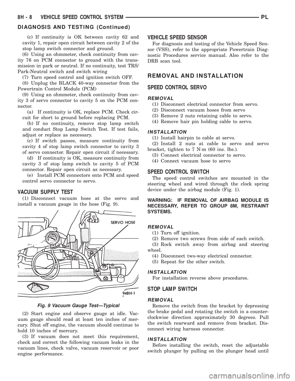
VACUUM SUPPLY TEST
(1) Disconnect vacuum hose at the servo and
install a vacuum gauge in the hose (Fig. 9).
(2) Start engine and observe gauge at idle. Vac-
uum gauge should read at least ten inches of mer-
cury. Shut off engine, the vacuum should continue to
hold 10 inches of mercury.
(3) If vacuum does not meet this requirement,
check and correct the following vacuum leaks in the
vacuum lines, check valve, vacuum reservoir or poor
engine performance.
VEHICLE SPEED SENSOR
For diagnosis and testing of the Vehicle Speed Sen-
sor (VSS), refer to the appropriate Powertrain Diag-
nostic Procedures service manual. Also refer to the
DRB scan tool.
REMOVAL AND INSTALLATION
SPEED CONTROL SERVO
REMOVAL
(1) Disconnect electrical connector from servo.
(2) Disconnect vacuum hoses from servo
(3) Remove 2 nuts retaining cable to servo.
(4) Remove hair pin holding cable to servo.
INSTALLATION
(1) Install hairpin to cable at servo.
(2) Install 2 nuts at cable to servo and servo
bracket, tighten to 7 N´m (60 ins. lbs.).
(3) Connect electrical connector to servo.
(4) Connect vacuum hose to servo
SPEED CONTROL SWITCH
The speed control switches are mounted in the
steering wheel and wired through the clock spring
device under the airbag module (Fig. 1).
WARNING: IF REMOVAL OF AIRBAG MODULE IS
NECESSARY, REFER TO GROUP 8M, RESTRAINT
SYSTEMS.
REMOVAL
(1) Turn off ignition.
(2) Remove two screws from side of each switch.
(3) Rock switch away from airbag and steering
wheel.
(4) Disconnect two-way electrical connector.
(5) Repeat for the other switch.
INSTALLATION
For installation reverse above procedures.
STOP LAMP SWITCH
REMOVAL
Remove the switch from the bracket by depressing
the brake pedal and rotating the switch in a counter-
clockwise direction approximately 30 degrees. Pull
the switch rearward and remove from bracket. Dis-
connect wiring harness connector.
INSTALLATION
Before installing the switch, reset the adjustable
switch plunger by pulling on the plunger head until
Fig. 9 Vacuum Gauge TestÐTypical
8H - 8 VEHICLE SPEED CONTROL SYSTEMPL
DIAGNOSIS AND TESTING (Continued)
Page 310 of 1200
TURN SIGNAL AND FLASHERS
CONTENTS
page page
GENERAL INFORMATION
INTRODUCTION......................... 1
DESCRIPTION AND OPERATION
COMBINATION FLASHER.................. 1
HAZARD WARNING SYSTEM............... 1DIAGNOSIS AND TESTING
MULTI-FUNCTION SWITCH................ 2
MULTI-FUNCTION SWITCH TEST............ 2
REMOVAL AND INSTALLATION
MULTI-FUNCTION SWITCH................ 4
GENERAL INFORMATION
INTRODUCTION
WARNING: ON VEHICLES EQUIPPED WITH AIR-
BAG, SEE GROUP 8M, RESTRAINT SYSTEMS FOR
AIRBAG REMOVAL PROCEDURES.
The turn signals are part of the multi-function
switch. Which contains:
²Electrical circuitry for turn signals
²Hazard warning switch
²Headlamp beam select switch
²Headlamp optical horn
The integrated switch assembly is mounted to the
left hand side of the steering column. When the
driver wishes to signal his intentions to change direc-
tion of travel, he moves the lever upward to cause
the right signals to flash and downward to cause the
left signals to flash. After completion of a turn the
system is deactivated automatically. As the steering
wheel returns to the straight ahead position, a can-
celing cam molded to the clockspring mechanism
comes in contact with the cancel actuator on the turn
signal multi-function switch assembly. The cam lobe,
pushing on the cancel actuator, returns the switch to
the off position.
If only momentary signaling such as indication of a
lane change is desired, the switch is actuated to a
left or right intermediate detent position. In this
position the signal lamps flash as described above,
but the switch returns to the OFF position as soon as
the lever is released.
When the system is activated, one of two indicator
lamps mounted in the instrument cluster flashes in
unison with the turn signal lamps, indicating to the
driver that the system is operating.
DESCRIPTION AND OPERATION
HAZARD WARNING SYSTEM
The hazard warning system is actuated by a slide
button located on the top of the steering column
between the steering wheel and the instrument
panel. The hazard switch is identified with a double
triangle on front of the button.
COMBINATION FLASHER
The turn signal flasher and the hazard warning
flasher are combined into one unit called a combina-
tion flasher (combo-flasher). The combo- flasher con-
trols the flashing of the hazard warning system and
the turn signal system. An inoperative bulb or incom-
plete turn signal circuit will cause the flasher rate to
double.
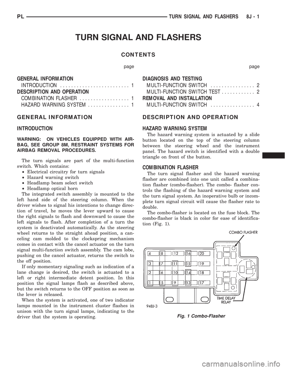
The combo-flasher is located on the fuse block. The
combo-flasher is black in color for ease of identifica-
tion (Fig. 1).
Fig. 1 Combo-Flasher
PLTURN SIGNAL AND FLASHERS 8J - 1
Page 311 of 1200
DIAGNOSIS AND TESTING
MULTI-FUNCTION SWITCH
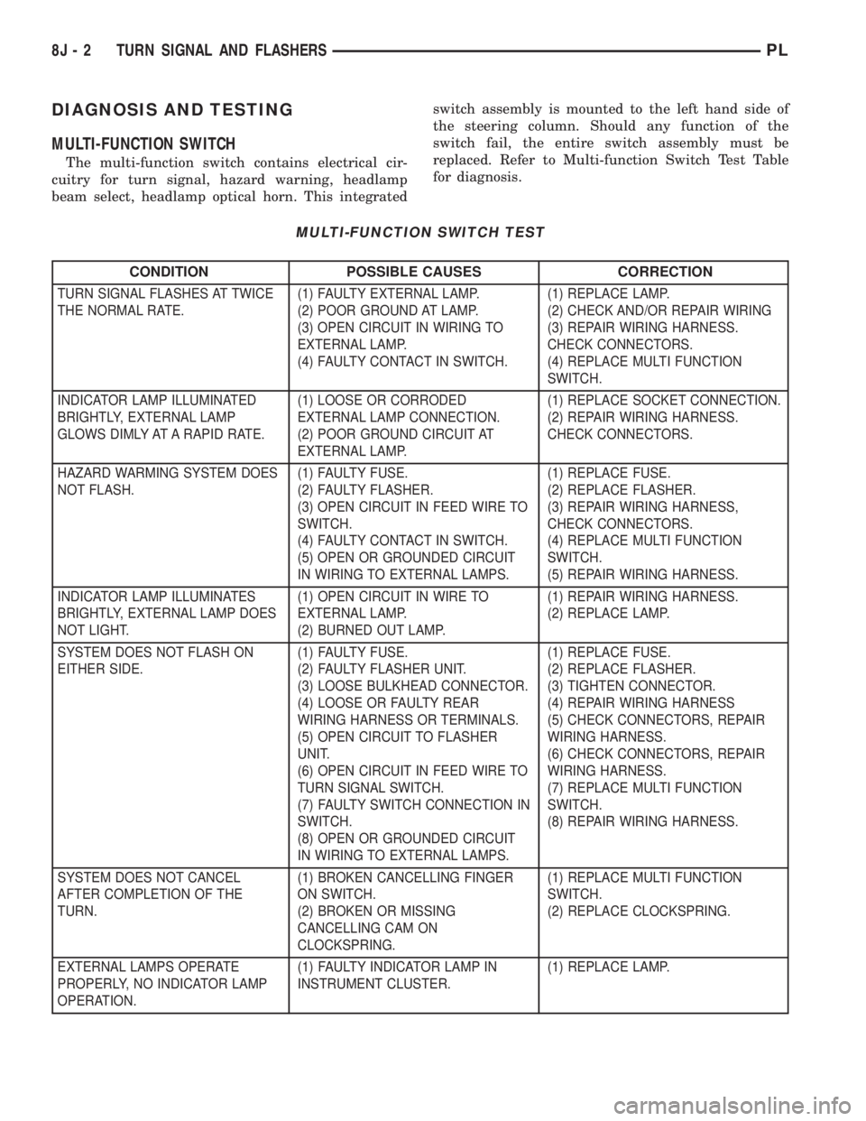
The multi-function switch contains electrical cir-
cuitry for turn signal, hazard warning, headlamp
beam select, headlamp optical horn. This integratedswitch assembly is mounted to the left hand side of
the steering column. Should any function of the
switch fail, the entire switch assembly must be
replaced. Refer to Multi-function Switch Test Table
for diagnosis.
MULTI-FUNCTION SWITCH TEST
CONDITION POSSIBLE CAUSES CORRECTION
TURN SIGNAL FLASHES AT TWICE
THE NORMAL RATE.(1) FAULTY EXTERNAL LAMP.
(2) POOR GROUND AT LAMP.
(3) OPEN CIRCUIT IN WIRING TO
EXTERNAL LAMP.
(4) FAULTY CONTACT IN SWITCH.(1) REPLACE LAMP.
(2) CHECK AND/OR REPAIR WIRING
(3) REPAIR WIRING HARNESS.
CHECK CONNECTORS.
(4) REPLACE MULTI FUNCTION
SWITCH.
INDICATOR LAMP ILLUMINATED
BRIGHTLY, EXTERNAL LAMP
GLOWS DIMLY AT A RAPID RATE.(1) LOOSE OR CORRODED
EXTERNAL LAMP CONNECTION.
(2) POOR GROUND CIRCUIT AT
EXTERNAL LAMP.(1) REPLACE SOCKET CONNECTION.
(2) REPAIR WIRING HARNESS.
CHECK CONNECTORS.
HAZARD WARMING SYSTEM DOES
NOT FLASH.(1) FAULTY FUSE.
(2) FAULTY FLASHER.
(3) OPEN CIRCUIT IN FEED WIRE TO
SWITCH.
(4) FAULTY CONTACT IN SWITCH.
(5) OPEN OR GROUNDED CIRCUIT
IN WIRING TO EXTERNAL LAMPS.(1) REPLACE FUSE.
(2) REPLACE FLASHER.
(3) REPAIR WIRING HARNESS,
CHECK CONNECTORS.
(4) REPLACE MULTI FUNCTION
SWITCH.
(5) REPAIR WIRING HARNESS.
INDICATOR LAMP ILLUMINATES
BRIGHTLY, EXTERNAL LAMP DOES
NOT LIGHT.(1) OPEN CIRCUIT IN WIRE TO
EXTERNAL LAMP.
(2) BURNED OUT LAMP.(1) REPAIR WIRING HARNESS.
(2) REPLACE LAMP.
SYSTEM DOES NOT FLASH ON
EITHER SIDE.(1) FAULTY FUSE.
(2) FAULTY FLASHER UNIT.
(3) LOOSE BULKHEAD CONNECTOR.
(4) LOOSE OR FAULTY REAR
WIRING HARNESS OR TERMINALS.
(5) OPEN CIRCUIT TO FLASHER
UNIT.
(6) OPEN CIRCUIT IN FEED WIRE TO
TURN SIGNAL SWITCH.
(7) FAULTY SWITCH CONNECTION IN
SWITCH.
(8) OPEN OR GROUNDED CIRCUIT
IN WIRING TO EXTERNAL LAMPS.(1) REPLACE FUSE.
(2) REPLACE FLASHER.
(3) TIGHTEN CONNECTOR.
(4) REPAIR WIRING HARNESS
(5) CHECK CONNECTORS, REPAIR
WIRING HARNESS.
(6) CHECK CONNECTORS, REPAIR
WIRING HARNESS.
(7) REPLACE MULTI FUNCTION
SWITCH.
(8) REPAIR WIRING HARNESS.
SYSTEM DOES NOT CANCEL
AFTER COMPLETION OF THE
TURN.(1) BROKEN CANCELLING FINGER
ON SWITCH.
(2) BROKEN OR MISSING
CANCELLING CAM ON
CLOCKSPRING.(1) REPLACE MULTI FUNCTION
SWITCH.
(2) REPLACE CLOCKSPRING.
EXTERNAL LAMPS OPERATE
PROPERLY, NO INDICATOR LAMP
OPERATION.(1) FAULTY INDICATOR LAMP IN
INSTRUMENT CLUSTER.(1) REPLACE LAMP.
8J - 2 TURN SIGNAL AND FLASHERSPL
Page 314 of 1200
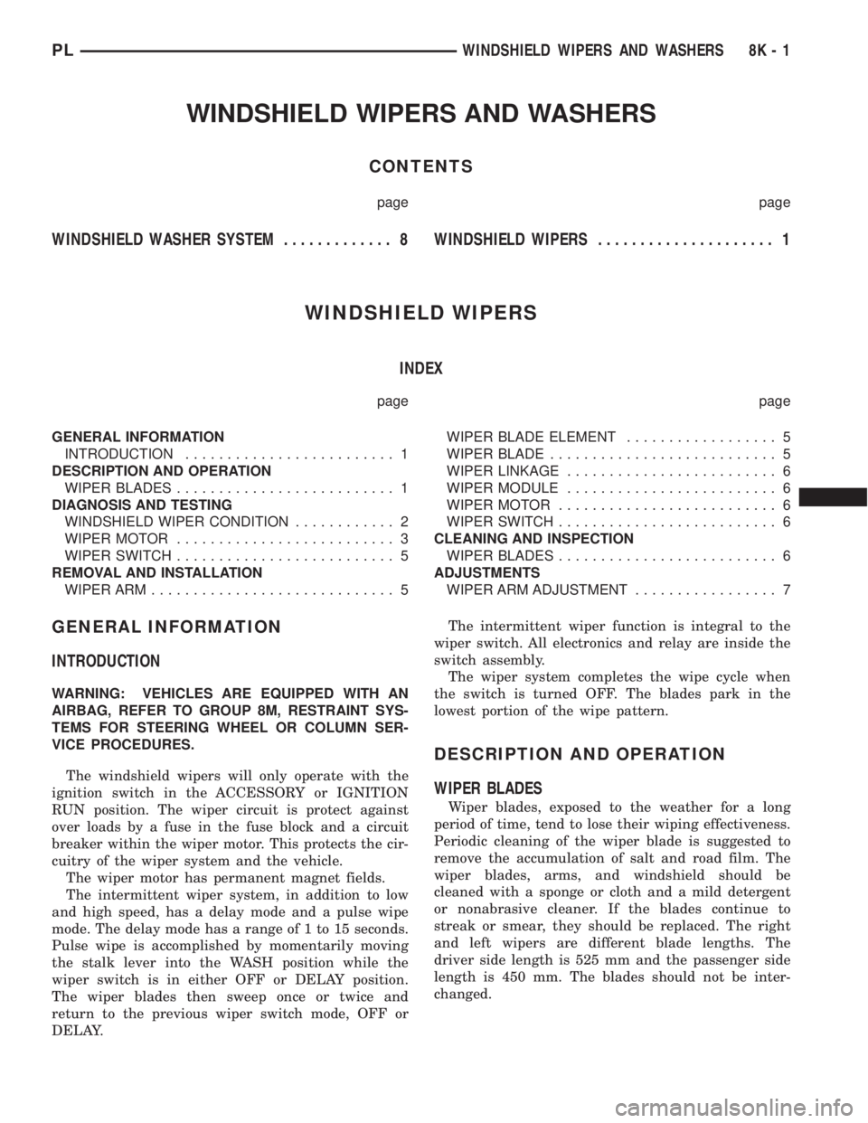
WINDSHIELD WIPERS AND WASHERS
CONTENTS
page page
WINDSHIELD WASHER SYSTEM............. 8WINDSHIELD WIPERS..................... 1
WINDSHIELD WIPERS
INDEX
page page
GENERAL INFORMATION
INTRODUCTION......................... 1
DESCRIPTION AND OPERATION
WIPER BLADES.......................... 1
DIAGNOSIS AND TESTING
WINDSHIELD WIPER CONDITION............ 2
WIPER MOTOR.......................... 3
WIPER SWITCH.......................... 5
REMOVAL AND INSTALLATION
WIPER ARM............................. 5WIPER BLADE ELEMENT.................. 5
WIPER BLADE........................... 5
WIPER LINKAGE......................... 6
WIPER MODULE......................... 6
WIPER MOTOR.......................... 6
WIPER SWITCH.......................... 6
CLEANING AND INSPECTION
WIPER BLADES.......................... 6
ADJUSTMENTS
WIPER ARM ADJUSTMENT................. 7
GENERAL INFORMATION
INTRODUCTION
WARNING: VEHICLES ARE EQUIPPED WITH AN
AIRBAG, REFER TO GROUP 8M, RESTRAINT SYS-
TEMS FOR STEERING WHEEL OR COLUMN SER-
VICE PROCEDURES.
The windshield wipers will only operate with the
ignition switch in the ACCESSORY or IGNITION
RUN position. The wiper circuit is protect against
over loads by a fuse in the fuse block and a circuit
breaker within the wiper motor. This protects the cir-
cuitry of the wiper system and the vehicle.
The wiper motor has permanent magnet fields.
The intermittent wiper system, in addition to low
and high speed, has a delay mode and a pulse wipe
mode. The delay mode has a range of 1 to 15 seconds.
Pulse wipe is accomplished by momentarily moving
the stalk lever into the WASH position while the
wiper switch is in either OFF or DELAY position.
The wiper blades then sweep once or twice and
return to the previous wiper switch mode, OFF or
DELAY.The intermittent wiper function is integral to the
wiper switch. All electronics and relay are inside the
switch assembly.
The wiper system completes the wipe cycle when
the switch is turned OFF. The blades park in the
lowest portion of the wipe pattern.
DESCRIPTION AND OPERATION
WIPER BLADES
Wiper blades, exposed to the weather for a long
period of time, tend to lose their wiping effectiveness.
Periodic cleaning of the wiper blade is suggested to
remove the accumulation of salt and road film. The
wiper blades, arms, and windshield should be
cleaned with a sponge or cloth and a mild detergent
or nonabrasive cleaner. If the blades continue to
streak or smear, they should be replaced. The right
and left wipers are different blade lengths. The
driver side length is 525 mm and the passenger side
length is 450 mm. The blades should not be inter-
changed.
PLWINDSHIELD WIPERS AND WASHERS 8K - 1
Page 315 of 1200
DIAGNOSIS AND TESTING
WINDSHIELD WIPER CONDITION
WARNING: ON VEHICLES EQUIPPED WITH AIR-
BAGS, SEE GROUP 8M, RESTRAINT SYSTEMS FOR
STEERING WHEEL OR COLUMN REMOVAL PROCE-
DURES.
The following is a list of general wiper motor sys-
tem problems, the tests that are to be performed to
locate the faulty part, and the corrective action to be
taken.
Whatever the problem, disconnect motor wire har-
ness and clean the terminals, then connect motor
wire harness and test.
MOTOR WILL NOT OPERATE IN SOME OR ALL
SWITCH POSITIONS
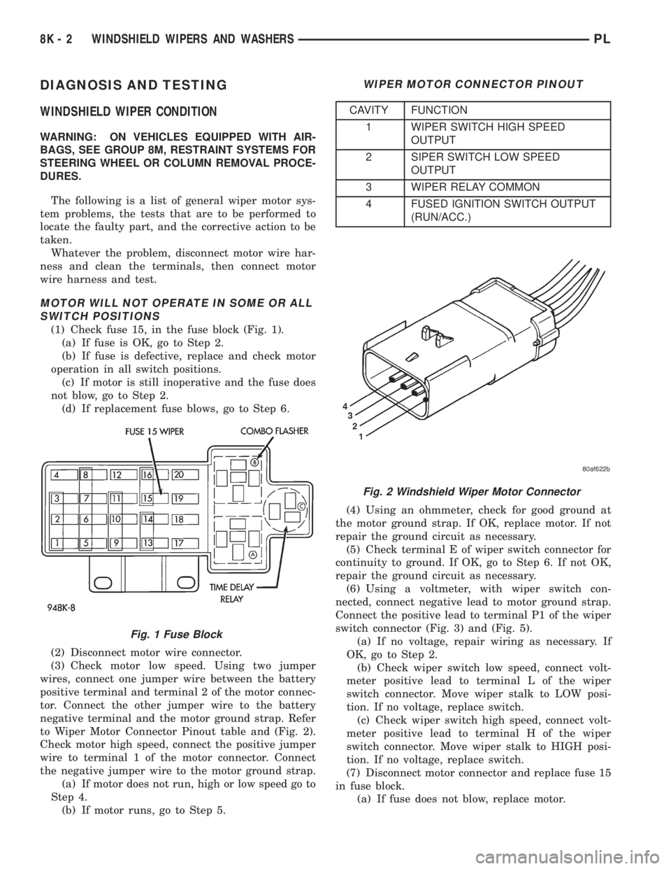
(1) Check fuse 15, in the fuse block (Fig. 1).
(a) If fuse is OK, go to Step 2.
(b) If fuse is defective, replace and check motor
operation in all switch positions.
(c) If motor is still inoperative and the fuse does
not blow, go to Step 2.
(d) If replacement fuse blows, go to Step 6.
(2) Disconnect motor wire connector.
(3) Check motor low speed. Using two jumper
wires, connect one jumper wire between the battery
positive terminal and terminal 2 of the motor connec-
tor. Connect the other jumper wire to the battery
negative terminal and the motor ground strap. Refer
to Wiper Motor Connector Pinout table and (Fig. 2).
Check motor high speed, connect the positive jumper
wire to terminal 1 of the motor connector. Connect
the negative jumper wire to the motor ground strap.
(a) If motor does not run, high or low speed go to
Step 4.
(b) If motor runs, go to Step 5.(4) Using an ohmmeter, check for good ground at
the motor ground strap. If OK, replace motor. If not
repair the ground circuit as necessary.
(5) Check terminal E of wiper switch connector for
continuity to ground. If OK, go to Step 6. If not OK,
repair the ground circuit as necessary.
(6) Using a voltmeter, with wiper switch con-
nected, connect negative lead to motor ground strap.
Connect the positive lead to terminal P1 of the wiper
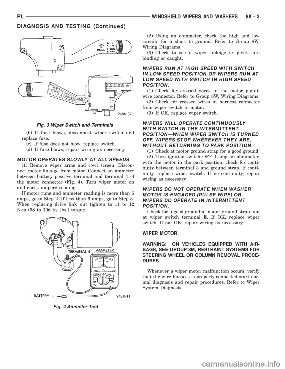
switch connector (Fig. 3) and (Fig. 5).
(a) If no voltage, repair wiring as necessary. If
OK, go to Step 2.
(b) Check wiper switch low speed, connect volt-
meter positive lead to terminal L of the wiper
switch connector. Move wiper stalk to LOW posi-
tion. If no voltage, replace switch.
(c) Check wiper switch high speed, connect volt-
meter positive lead to terminal H of the wiper
switch connector. Move wiper stalk to HIGH posi-
tion. If no voltage, replace switch.
(7) Disconnect motor connector and replace fuse 15
in fuse block.
(a) If fuse does not blow, replace motor.
Fig. 1 Fuse Block
WIPER MOTOR CONNECTOR PINOUT
CAVITY FUNCTION
1 WIPER SWITCH HIGH SPEED
OUTPUT
2 SIPER SWITCH LOW SPEED
OUTPUT
3 WIPER RELAY COMMON
4 FUSED IGNITION SWITCH OUTPUT
(RUN/ACC.)
Fig. 2 Windshield Wiper Motor Connector
8K - 2 WINDSHIELD WIPERS AND WASHERSPL
Page 316 of 1200
(b) If fuse blows, disconnect wiper switch and
replace fuse.
(c) If fuse does not blow, replace switch.
(d) If fuse blows, repair wiring as necessary.
MOTOR OPERATES SLOWLY AT ALL SPEEDS
(1) Remove wiper arms and cowl screen. Discon-
nect motor linkage from motor. Connect an ammeter
between battery positive terminal and terminal 4 of
the motor connector (Fig. 4). Turn wiper motor on
and check ampere reading.
If motor runs and ammeter reading is more than 6
amps, go to Step 2. If less than 6 amps, go to Step 3.
When replacing drive link nut tighten to 11 to 12
N´m (98 to 106 in. lbs.) torque.(2) Using an ohmmeter, check the high and low
circuits for a short to ground. Refer to Group 8W,
Wiring Diagrams.
(3) Check to see if wiper linkage or pivots are
binding or caught.
WIPERS RUN AT HIGH SPEED WITH SWITCH
IN LOW SPEED POSITION OR WIPERS RUN AT
LOW SPEED WITH SWITCH IN HIGH SPEED
POSITION.
(1) Check for crossed wires in the motor pigtail
wire connector. Refer to Group 8W, Wiring Diagrams.
(2) Check for crossed wires in harness connector
from wiper switch to motor.
(3) If OK, replace wiper switch.
WIPERS WILL OPERATE CONTINUOUSLY
WITH SWITCH IN THE INTERMITTENT
POSITIONÐWHEN WIPER SWITCH IS TURNED
OFF, WIPERS STOP WHEREVER THEY ARE,
WITHOUT RETURNING TO PARK POSITION.
(1) Check at motor ground strap for a good ground.
(2) Turn ignition switch OFF. Using an ohmmeter,
with the motor in the park position, check for conti-
nuity between terminal 3 and ground strap. If conti-
nuity, replace wiper switch. If no continuity, repair
wiring as necessary.
WIPERS DO NOT OPERATE WHEN WASHER
MOTOR IS ENGAGED (PULSE WIPE) OR
WIPERS DO OPERATE IN INTERMITTENT
POSITION.
Check for a good ground at motor ground strap and
at wiper switch terminal E. If OK, replace wiper
switch. If not OK, repair wiring as necessary.
WIPER MOTOR
WARNING: ON VEHICLES EQUIPPED WITH AIR-
BAGS, SEE GROUP 8M, RESTRAINT SYSTEMS FOR
STEERING WHEEL OR COLUMN REMOVAL PROCE-
DURES.
Whenever a wiper motor malfunction occurs, verify
that the wire harness is properly connected start nor-
mal diagnosis and repair procedures. Refer to Wiper
System Diagnosis.
Fig. 3 Wiper Switch and Terminals
Fig. 4 Ammeter Test
PLWINDSHIELD WIPERS AND WASHERS 8K - 3
DIAGNOSIS AND TESTING (Continued)
Page 324 of 1200
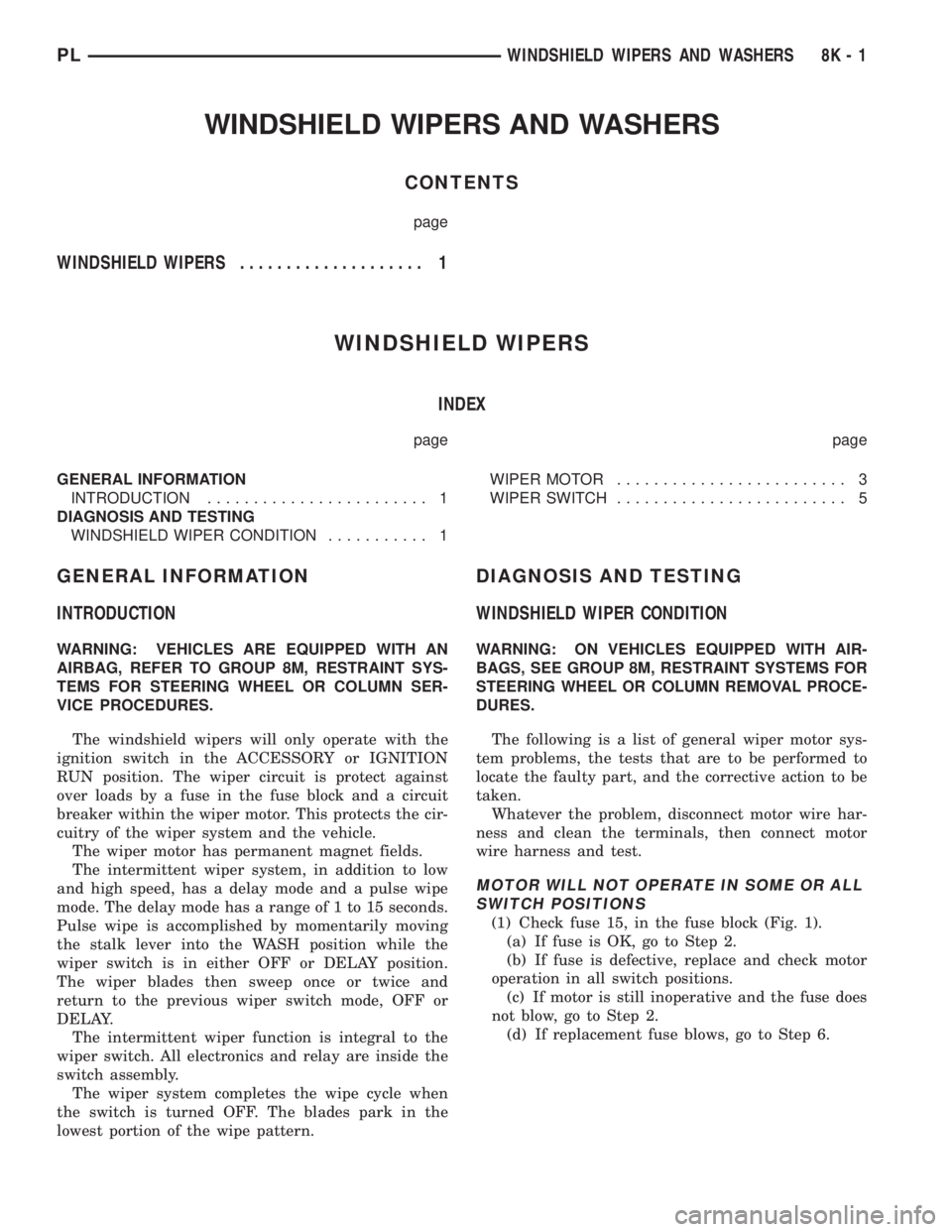
WINDSHIELD WIPERS AND WASHERS
CONTENTS
page
WINDSHIELD WIPERS.................... 1
WINDSHIELD WIPERS
INDEX
page page
GENERAL INFORMATION
INTRODUCTION........................ 1
DIAGNOSIS AND TESTING
WINDSHIELD WIPER CONDITION........... 1WIPER MOTOR......................... 3
WIPER SWITCH......................... 5
GENERAL INFORMATION
INTRODUCTION
WARNING: VEHICLES ARE EQUIPPED WITH AN
AIRBAG, REFER TO GROUP 8M, RESTRAINT SYS-
TEMS FOR STEERING WHEEL OR COLUMN SER-
VICE PROCEDURES.
The windshield wipers will only operate with the
ignition switch in the ACCESSORY or IGNITION
RUN position. The wiper circuit is protect against
over loads by a fuse in the fuse block and a circuit
breaker within the wiper motor. This protects the cir-
cuitry of the wiper system and the vehicle.
The wiper motor has permanent magnet fields.
The intermittent wiper system, in addition to low
and high speed, has a delay mode and a pulse wipe
mode. The delay mode has a range of 1 to 15 seconds.
Pulse wipe is accomplished by momentarily moving
the stalk lever into the WASH position while the
wiper switch is in either OFF or DELAY position.
The wiper blades then sweep once or twice and
return to the previous wiper switch mode, OFF or
DELAY.
The intermittent wiper function is integral to the
wiper switch. All electronics and relay are inside the
switch assembly.
The wiper system completes the wipe cycle when
the switch is turned OFF. The blades park in the
lowest portion of the wipe pattern.
DIAGNOSIS AND TESTING
WINDSHIELD WIPER CONDITION
WARNING: ON VEHICLES EQUIPPED WITH AIR-
BAGS, SEE GROUP 8M, RESTRAINT SYSTEMS FOR
STEERING WHEEL OR COLUMN REMOVAL PROCE-
DURES.
The following is a list of general wiper motor sys-
tem problems, the tests that are to be performed to
locate the faulty part, and the corrective action to be
taken.
Whatever the problem, disconnect motor wire har-
ness and clean the terminals, then connect motor
wire harness and test.
MOTOR WILL NOT OPERATE IN SOME OR ALL
SWITCH POSITIONS
(1) Check fuse 15, in the fuse block (Fig. 1).
(a) If fuse is OK, go to Step 2.
(b) If fuse is defective, replace and check motor
operation in all switch positions.
(c) If motor is still inoperative and the fuse does
not blow, go to Step 2.
(d) If replacement fuse blows, go to Step 6.
PLWINDSHIELD WIPERS AND WASHERS 8K - 1