1999 DODGE NEON warning
[x] Cancel search: warningPage 256 of 1200
train Control Module (PCM) with an input signal
(voltage). The signal represents throttle blade posi-
tion. As the position of the throttle blade changes,
the resistance of the TPS changes.
The PCM supplies approximately 5 volts to the
TPS. The TPS output voltage (input signal to the
powertrain control module) represents throttle blade
position. The TPS output voltage to the PCM varies
from approximately 0.38 volts to 1.2 volts at mini-
mum throttle opening (idle) to a maximum of 3.1
volts to 4.4 volts at wide open throttle.
Along with inputs from other sensors, the PCM
uses the TPS input to determine current engine oper-
ating conditions. The PCM also adjusts fuel injector
pulse width and ignition timing based on these
inputs.
IGNITION SWITCH
In the RUN position, the ignition switch connects
power from the Power Distribution Center (PDC) to a
30 amp fuse in the fuse block, back to a bus bar in
the PDC. The bus bar feeds circuits for the Power-
train Control Module (PCM), duty cycle purge sole-
noid, EGR solenoid, and ABS system. The bus bar in
the PDC feeds the coil side of the radiator fan relay,
A/C compressor clutch relay, and the fuel pump relay.
It also feeds the Airbag Control Module (ACM)
LOCK KEY CYLINDER
The lock cylinder is inserted in the end of the
housing opposite the ignition switch. The ignition key
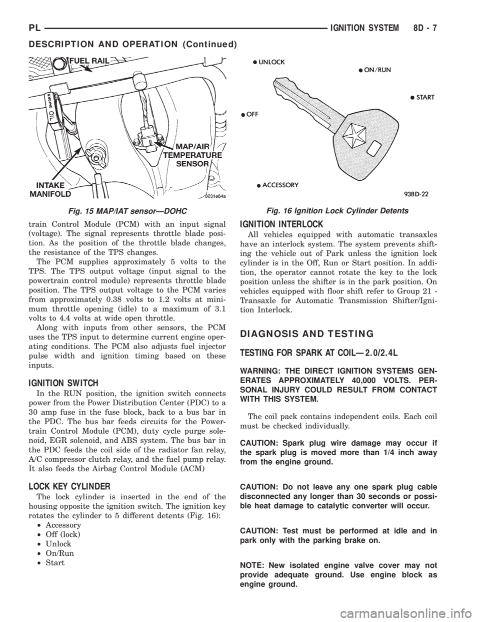
rotates the cylinder to 5 different detents (Fig. 16):
²Accessory
²Off (lock)
²Unlock
²On/Run
²Start
IGNITION INTERLOCK
All vehicles equipped with automatic transaxles
have an interlock system. The system prevents shift-
ing the vehicle out of Park unless the ignition lock
cylinder is in the Off, Run or Start position. In addi-
tion, the operator cannot rotate the key to the lock
position unless the shifter is in the park position. On
vehicles equipped with floor shift refer to Group 21 -
Transaxle for Automatic Transmission Shifter/Igni-
tion Interlock.
DIAGNOSIS AND TESTING
TESTING FOR SPARK AT COILÐ2.0/2.4L
WARNING: THE DIRECT IGNITION SYSTEMS GEN-
ERATES APPROXIMATELY 40,000 VOLTS. PER-
SONAL INJURY COULD RESULT FROM CONTACT
WITH THIS SYSTEM.
The coil pack contains independent coils. Each coil
must be checked individually.
CAUTION: Spark plug wire damage may occur if
the spark plug is moved more than 1/4 inch away
from the engine ground.
CAUTION: Do not leave any one spark plug cable
disconnected any longer than 30 seconds or possi-
ble heat damage to catalytic converter will occur.
CAUTION: Test must be performed at idle and in
park only with the parking brake on.
NOTE: New isolated engine valve cover may not
provide adequate ground. Use engine block as
engine ground.
Fig. 15 MAP/IAT sensorÐDOHCFig. 16 Ignition Lock Cylinder Detents
PLIGNITION SYSTEM 8D - 7
DESCRIPTION AND OPERATION (Continued)
Page 266 of 1200
(3) Install electrical connectors to ignition switch.
(4) Install upper and lower shrouds.
(5) Install key cylinder (cylinder retaining tab will
depress only in the RUN position).
(6) Connect negative cable to battery.
(7) Check for proper operation of ignition switch
and key-in warning switch.
LOCK KEY CYLINDER
The lock cylinder is inserted in the end of the
housing opposite the ignition switch. The ignition key
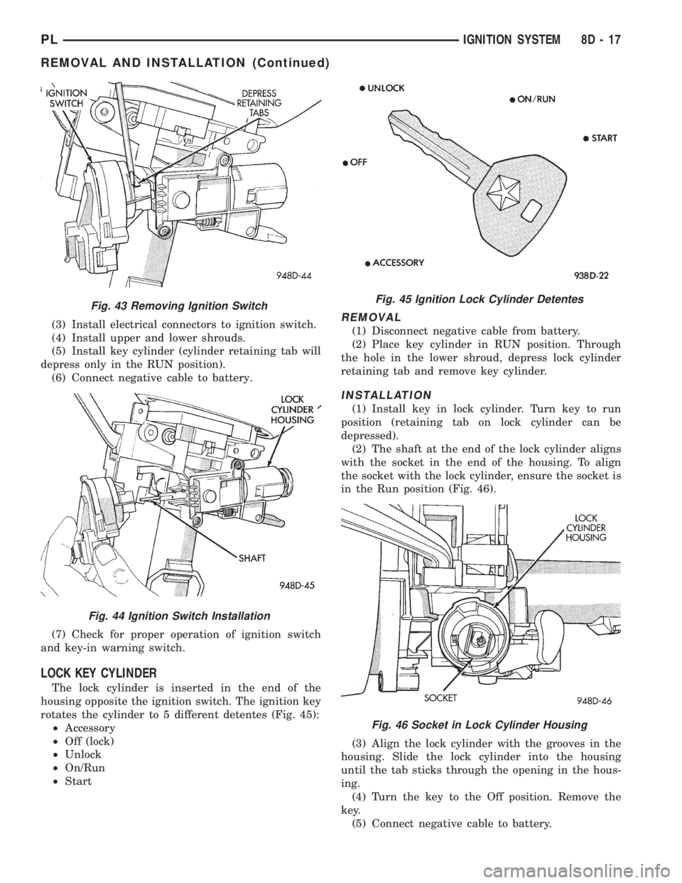
rotates the cylinder to 5 different detentes (Fig. 45):
²Accessory
²Off (lock)
²Unlock
²On/Run
²Start
REMOVAL
(1) Disconnect negative cable from battery.
(2) Place key cylinder in RUN position. Through
the hole in the lower shroud, depress lock cylinder
retaining tab and remove key cylinder.
INSTALLATION
(1) Install key in lock cylinder. Turn key to run
position (retaining tab on lock cylinder can be
depressed).
(2) The shaft at the end of the lock cylinder aligns
with the socket in the end of the housing. To align
the socket with the lock cylinder, ensure the socket is
in the Run position (Fig. 46).
(3) Align the lock cylinder with the grooves in the
housing. Slide the lock cylinder into the housing
until the tab sticks through the opening in the hous-
ing.
(4) Turn the key to the Off position. Remove the
key.
(5) Connect negative cable to battery.
Fig. 43 Removing Ignition Switch
Fig. 44 Ignition Switch Installation
Fig. 45 Ignition Lock Cylinder Detentes
Fig. 46 Socket in Lock Cylinder Housing
PLIGNITION SYSTEM 8D - 17
REMOVAL AND INSTALLATION (Continued)
Page 270 of 1200
INSTRUMENT PANEL AND SYSTEMS
CONTENTS
page page
GENERAL INFORMATION
INTRODUCTION......................... 1
DESCRIPTION AND OPERATION
DOME LAMP............................ 1
ELECTRONIC DIGITAL CLOCK.............. 1
INSTRUMENT CLUSTER................... 2
WARNING AND INDICATOR LAMPS......... 2
DIAGNOSIS AND TESTING
AIRBAG WARNING SYSTEM............... 2
BRAKE SYSTEM WARNING LAMP TEST...... 2
FOG LAMP SWITCH TEST................. 2
FUEL TANK SENDING UNIT TEST........... 3
HEADLAMP SWITCH TEST................. 3
HEATER A/C BLOWER SWITCH TEST........ 3
HEATER BLOWER SWITCH TEST............ 3
INDIVIDUAL GAUGE INOPERATIVE.......... 4
INSTRUMENT PANEL AND COMPONENTS.... 4
LOW OIL PRESSURE WARNING LAMP TEST . . 4
MULTIPLE GAUGE INOPERATIVE TEST....... 4
SEAT BELT REMINDER SYSTEM TEST....... 6
SENDING UNIT......................... 6
SERVICE ENGINE SOON INDICATOR......... 6
VEHICLE SPEED SENSOR TEST............. 6
REMOVAL AND INSTALLATION
ASH RECEIVER RETAINER AND LAMP....... 6
CENTER BEZEL.......................... 6
CIGAR LIGHTER RECEPTACLE.............. 6
CLUSTER LAMP......................... 7
CLUSTER PRINTED CIRCUIT BOARD........ 7CLUSTER.............................. 7
DOME LENS/LAMP....................... 8
FLOOR CONSOLE........................ 8
GAUGE................................ 8
GLOVE BOX DOOR/BIN................... 8
GLOVE BOX SWITCH/LAMP................ 9
HEADLAMP SWITCH..................... 9
HEATER A/C CONTROL BLOWER SWITCH . . . 10
HEATER A/C CONTROL LAMP............ 10
HEATER A/C CONTROL................... 9
HEATER CONTROL BLOWER SWITCH....... 10
IGNITION KEY LAMP.................... 10
INSTRUMENT PANEL.................... 10
LEFT TRIM PANEL...................... 10
ODOMETER............................ 10
RADIO................................ 12
REAR WINDOW DEFOGGER AND/OR FOG
LAMP SWITCH....................... 12
RIGHT TRIM PANEL..................... 12
SHIFTER KNOB......................... 13
STEERING COLUMN COVER LINER......... 13
STEERING COLUMN COVER.............. 13
STEERING COLUMN SHROUDS............ 13
TOP COVER AND CLUSTER BEZEL
REMOVAL........................... 14
TRANSMISSION RANGE INDICATOR LAMP . . 14
TRUNK LAMP/LENS..................... 14
VEHICLE SPEED SENSOR................ 14
GENERAL INFORMATION
INTRODUCTION
The purpose of the dash gauges and indicator
lamps is to keep the driver informed about the oper-
ating condition of the vehicle. If an abnormal condi-
tion occurs, the driver is informed by indicator lamp.
The driver can seek service before damage occurs.
Indicator lamps use ON/OFF switch functions for
operation, while gauges use a sending unit or sensor.
DESCRIPTION AND OPERATION
DOME LAMP
The Dome Lamp operates when a door is open or
when the headlamp switch is placed in courtesy posi-
tion.
ELECTRONIC DIGITAL CLOCK
The electronic digital clock is in the radio. The
clock and radio each use the display panel built into
the radio. A digital readout indicates the time in
hours and minutes whenever the ignition switch is in
the ON or ACC position.
PLINSTRUMENT PANEL AND SYSTEMS 8E - 1
Page 271 of 1200
When the ignition switch is in the OFF position, or
when the radio frequency is being displayed, time
keeping is accurately maintained.
The procedure for setting the clock varies slightly
with each radio. The correct procedure is described in
the individual radio operating instructions. Refer to
the Owner's Manual supplied with the vehicle.
INSTRUMENT CLUSTER
There are two conventional instrument cluster
assemblies available. The clusters electronically drive
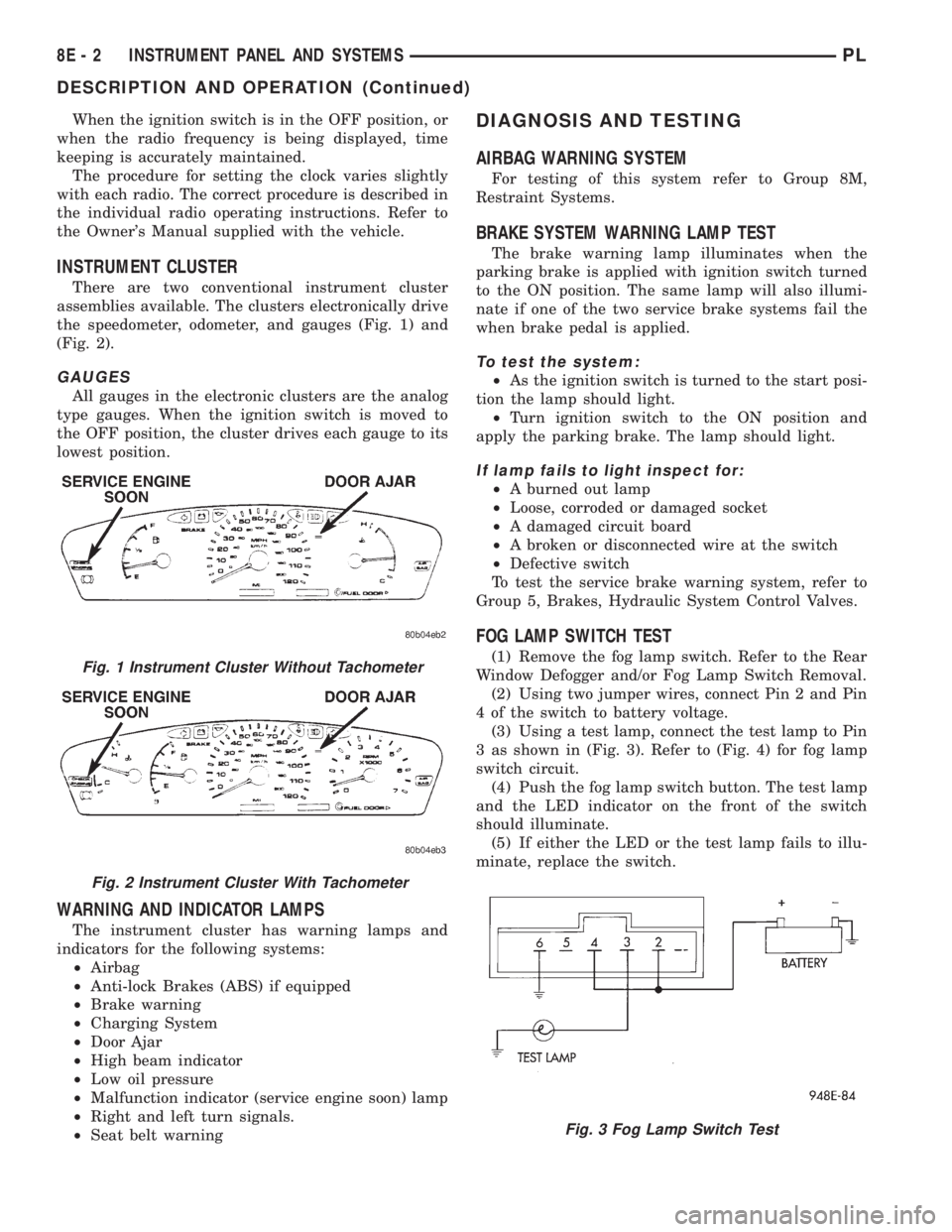
the speedometer, odometer, and gauges (Fig. 1) and
(Fig. 2).
GAUGES
All gauges in the electronic clusters are the analog
type gauges. When the ignition switch is moved to
the OFF position, the cluster drives each gauge to its
lowest position.
WARNING AND INDICATOR LAMPS
The instrument cluster has warning lamps and
indicators for the following systems:
²Airbag
²Anti-lock Brakes (ABS) if equipped
²Brake warning
²Charging System
²Door Ajar
²High beam indicator
²Low oil pressure
²Malfunction indicator (service engine soon) lamp
²Right and left turn signals.
²Seat belt warning
DIAGNOSIS AND TESTING
AIRBAG WARNING SYSTEM
For testing of this system refer to Group 8M,
Restraint Systems.
BRAKE SYSTEM WARNING LAMP TEST
The brake warning lamp illuminates when the
parking brake is applied with ignition switch turned
to the ON position. The same lamp will also illumi-
nate if one of the two service brake systems fail the
when brake pedal is applied.
To test the system:
²As the ignition switch is turned to the start posi-
tion the lamp should light.
²Turn ignition switch to the ON position and
apply the parking brake. The lamp should light.
If lamp fails to light inspect for:
²A burned out lamp
²Loose, corroded or damaged socket
²A damaged circuit board
²A broken or disconnected wire at the switch
²Defective switch
To test the service brake warning system, refer to
Group 5, Brakes, Hydraulic System Control Valves.
FOG LAMP SWITCH TEST
(1) Remove the fog lamp switch. Refer to the Rear
Window Defogger and/or Fog Lamp Switch Removal.
(2) Using two jumper wires, connect Pin 2 and Pin
4 of the switch to battery voltage.
(3) Using a test lamp, connect the test lamp to Pin
3 as shown in (Fig. 3). Refer to (Fig. 4) for fog lamp
switch circuit.
(4) Push the fog lamp switch button. The test lamp
and the LED indicator on the front of the switch
should illuminate.
(5) If either the LED or the test lamp fails to illu-
minate, replace the switch.Fig. 1 Instrument Cluster Without Tachometer
Fig. 2 Instrument Cluster With Tachometer
Fig. 3 Fog Lamp Switch Test
8E - 2 INSTRUMENT PANEL AND SYSTEMSPL
DESCRIPTION AND OPERATION (Continued)
Page 273 of 1200
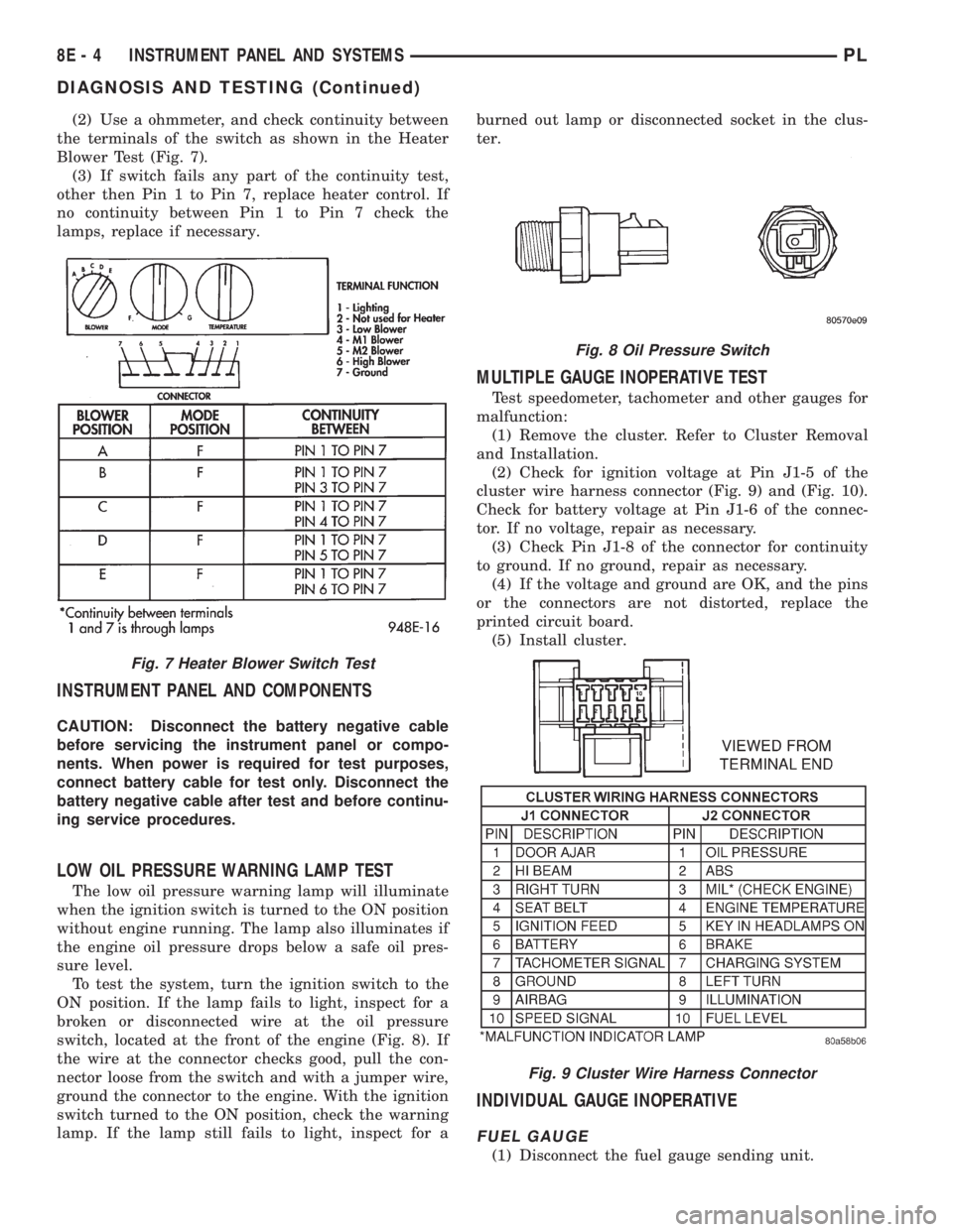
(2) Use a ohmmeter, and check continuity between
the terminals of the switch as shown in the Heater
Blower Test (Fig. 7).
(3) If switch fails any part of the continuity test,
other then Pin 1 to Pin 7, replace heater control. If
no continuity between Pin 1 to Pin 7 check the
lamps, replace if necessary.
INSTRUMENT PANEL AND COMPONENTS
CAUTION: Disconnect the battery negative cable
before servicing the instrument panel or compo-
nents. When power is required for test purposes,
connect battery cable for test only. Disconnect the
battery negative cable after test and before continu-
ing service procedures.
LOW OIL PRESSURE WARNING LAMP TEST
The low oil pressure warning lamp will illuminate
when the ignition switch is turned to the ON position
without engine running. The lamp also illuminates if
the engine oil pressure drops below a safe oil pres-
sure level.
To test the system, turn the ignition switch to the
ON position. If the lamp fails to light, inspect for a
broken or disconnected wire at the oil pressure
switch, located at the front of the engine (Fig. 8). If
the wire at the connector checks good, pull the con-
nector loose from the switch and with a jumper wire,
ground the connector to the engine. With the ignition
switch turned to the ON position, check the warning
lamp. If the lamp still fails to light, inspect for aburned out lamp or disconnected socket in the clus-
ter.
MULTIPLE GAUGE INOPERATIVE TEST
Test speedometer, tachometer and other gauges for
malfunction:
(1) Remove the cluster. Refer to Cluster Removal
and Installation.
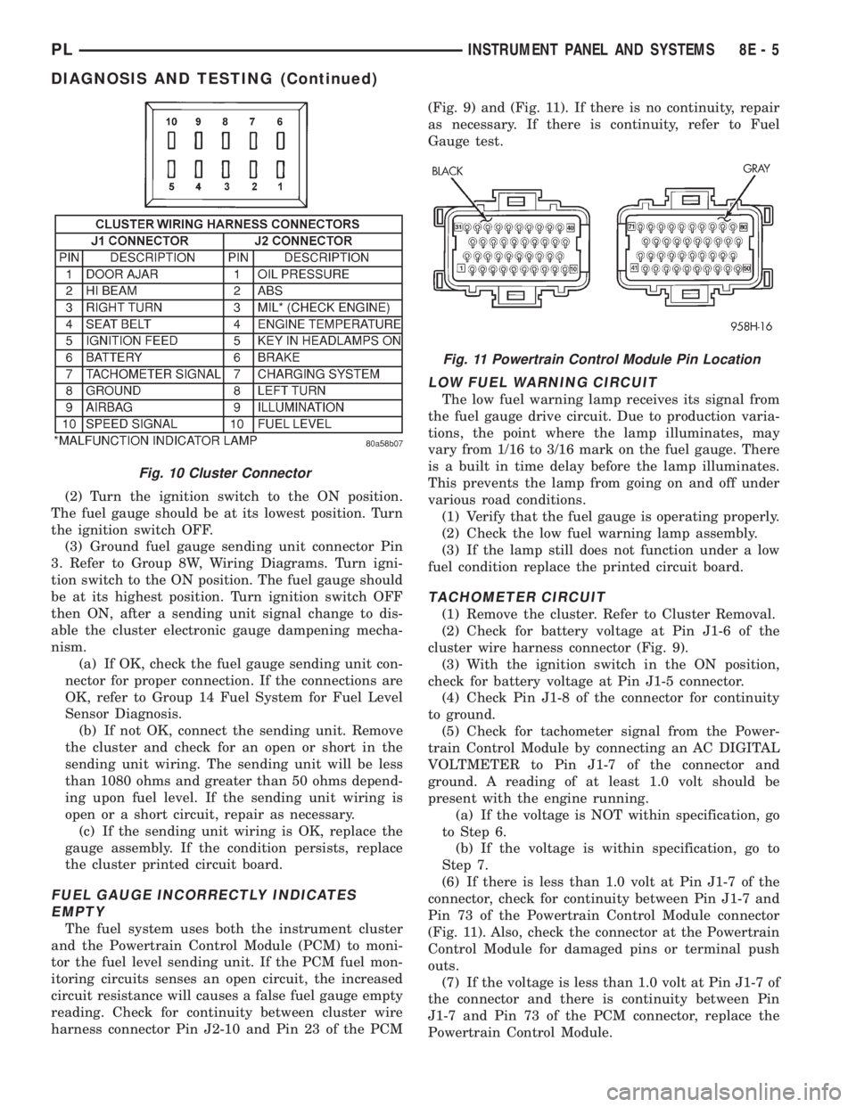
(2) Check for ignition voltage at Pin J1-5 of the
cluster wire harness connector (Fig. 9) and (Fig. 10).
Check for battery voltage at Pin J1-6 of the connec-
tor. If no voltage, repair as necessary.
(3) Check Pin J1-8 of the connector for continuity
to ground. If no ground, repair as necessary.
(4) If the voltage and ground are OK, and the pins
or the connectors are not distorted, replace the
printed circuit board.
(5) Install cluster.
INDIVIDUAL GAUGE INOPERATIVE
FUEL GAUGE
(1) Disconnect the fuel gauge sending unit.
Fig. 7 Heater Blower Switch Test
Fig. 8 Oil Pressure Switch
Fig. 9 Cluster Wire Harness Connector
8E - 4 INSTRUMENT PANEL AND SYSTEMSPL
DIAGNOSIS AND TESTING (Continued)
Page 274 of 1200
(2) Turn the ignition switch to the ON position.
The fuel gauge should be at its lowest position. Turn
the ignition switch OFF.
(3) Ground fuel gauge sending unit connector Pin
3. Refer to Group 8W, Wiring Diagrams. Turn igni-
tion switch to the ON position. The fuel gauge should
be at its highest position. Turn ignition switch OFF
then ON, after a sending unit signal change to dis-
able the cluster electronic gauge dampening mecha-
nism.
(a) If OK, check the fuel gauge sending unit con-
nector for proper connection. If the connections are
OK, refer to Group 14 Fuel System for Fuel Level
Sensor Diagnosis.
(b) If not OK, connect the sending unit. Remove
the cluster and check for an open or short in the
sending unit wiring. The sending unit will be less
than 1080 ohms and greater than 50 ohms depend-
ing upon fuel level. If the sending unit wiring is
open or a short circuit, repair as necessary.
(c) If the sending unit wiring is OK, replace the
gauge assembly. If the condition persists, replace
the cluster printed circuit board.
FUEL GAUGE INCORRECTLY INDICATES
EMPTY
The fuel system uses both the instrument cluster
and the Powertrain Control Module (PCM) to moni-
tor the fuel level sending unit. If the PCM fuel mon-
itoring circuits senses an open circuit, the increased
circuit resistance will causes a false fuel gauge empty
reading. Check for continuity between cluster wire
harness connector Pin J2-10 and Pin 23 of the PCM(Fig. 9) and (Fig. 11). If there is no continuity, repair
as necessary. If there is continuity, refer to Fuel
Gauge test.
LOW FUEL WARNING CIRCUIT
The low fuel warning lamp receives its signal from
the fuel gauge drive circuit. Due to production varia-
tions, the point where the lamp illuminates, may
vary from 1/16 to 3/16 mark on the fuel gauge. There
is a built in time delay before the lamp illuminates.
This prevents the lamp from going on and off under
various road conditions.
(1) Verify that the fuel gauge is operating properly.
(2) Check the low fuel warning lamp assembly.
(3) If the lamp still does not function under a low
fuel condition replace the printed circuit board.
TACHOMETER CIRCUIT
(1) Remove the cluster. Refer to Cluster Removal.
(2) Check for battery voltage at Pin J1-6 of the
cluster wire harness connector (Fig. 9).
(3) With the ignition switch in the ON position,
check for battery voltage at Pin J1-5 connector.
(4) Check Pin J1-8 of the connector for continuity
to ground.
(5) Check for tachometer signal from the Power-
train Control Module by connecting an AC DIGITAL
VOLTMETER to Pin J1-7 of the connector and
ground. A reading of at least 1.0 volt should be
present with the engine running.
(a) If the voltage is NOT within specification, go
to Step 6.
(b) If the voltage is within specification, go to
Step 7.
(6) If there is less than 1.0 volt at Pin J1-7 of the
connector, check for continuity between Pin J1-7 and
Pin 73 of the Powertrain Control Module connector
(Fig. 11). Also, check the connector at the Powertrain
Control Module for damaged pins or terminal push
outs.
(7) If the voltage is less than 1.0 volt at Pin J1-7 of
the connector and there is continuity between Pin
J1-7 and Pin 73 of the PCM connector, replace the
Powertrain Control Module.
Fig. 10 Cluster Connector
Fig. 11 Powertrain Control Module Pin Location
PLINSTRUMENT PANEL AND SYSTEMS 8E - 5
DIAGNOSIS AND TESTING (Continued)
Page 275 of 1200

(8) If all tests performed test good, replace the dial
and gauge assembly.
(9) If the tachometer continues to be inoperative,
replace the print circuit board.
TEMPERATURE GAUGE
(1) Disconnect the coolant temperature sensor
(Fig. 12).
(2) Turn ignition switch ON. The temperature
gauge should be at its lowest position. Turn ignition
switch OFF.
(3) Ground temperature gauge sending unit con-
nector Pin 3. Refer to Group 8W, wiring Diagrams.
Turn ignition switch ON. The temperature gauge
should be at its highest position. After the seat belt
lamp goes out, the cluster should chime for about
eight seconds.
(a) If OK, check temperature sending unit con-
nector for proper connection. If connections are OK,
replace the sending unit.
(b) If not OK, and the high temperature chime
sounds but the gauge shows cold, replace the gauge
assembly. If gauge is still not working, replace the
printed circuit board.
SPEEDOMETER SYSTEM
The vehicle is equipped with a electronically driven
speedometer and odometer assemblies. A signal is
sent from a transmission-mounted vehicle speed sen-
sor to the speedometer circuitry through the wiring
harness.
SEAT BELT REMINDER SYSTEM TEST
For testing of this system refer to Group 8U,
Chime Warning/Reminder Systems.
SENDING UNIT
When a problem occurs with a cluster gauge check
for a defective sending unit or wiring. Do this before
disassembling the cluster.(1) Sending units and wiring can be checked by
grounding the connector leads at the sending unit in
the vehicle.
(2) With the ignition in the ON position, a
grounded input will cause the fuel or temperature
gauge to read at or above maximum.
SERVICE ENGINE SOON INDICATOR
Refer to Group 25, Emission Control Systems for
procedures.
VEHICLE SPEED SENSOR TEST
To test the vehicle speed sensor and related compo-
nents use a scan tool (DRB), and refer to the appro-
priate Powertrain Diagnostics Test Procedure
Manual.
REMOVAL AND INSTALLATION
ASH RECEIVER RETAINER AND LAMP
REMOVAL
(1) Open up and remove the ash receiver recepta-
cle.
(2) Remove the center bezel.
(3) Remove the two ash receiver retainer attaching
screws from the upper-rearward face and remove
retainer.
(4) For lamp replacement, remove the clamp and
lamp hood from the top of the retainer. Remove the
wiring clip at the forward edge of the retainer and
remove the lamp socket from the hood and replace
lamp.
INSTALLATION
For installation reverse the above procedures.
When installing the retainer ensure that the forward
tabs are inserted properly into the slots in the instru-
ment panel.
CENTER BEZEL
REMOVAL
(1) Open the ash receiver receptacle.
(2) Grasp the bezel and pull rearward disengaging
the clips.
INSTALLATION
For installation, reverse the above procedures.
CIGAR LIGHTER RECEPTACLE
REMOVAL
(1) Remove the cigar lighter element.
(2) Reach underneath the instrument panel
through the bottom access hole and disconnect the
cigar lighter receptacle wiring connectors.
Fig. 12 Engine Coolant Temperature Sensor
8E - 6 INSTRUMENT PANEL AND SYSTEMSPL
DIAGNOSIS AND TESTING (Continued)
Page 294 of 1200
HORNS
CONTENTS
page page
DESCRIPTION AND OPERATION
INTRODUCTION......................... 1
DIAGNOSIS AND TESTING
HORN RELAY........................... 2
HORN SWITCH.......................... 2
HORN................................. 1SYSTEM TEST.......................... 2
REMOVAL AND INSTALLATION
HORN RELAY........................... 4
HORN SWITCHES........................ 4
HORN................................. 4
DESCRIPTION AND OPERATION
INTRODUCTION
WARNING: ON VEHICLES EQUIPPED WITH AIR-
BAG, SEE GROUP 8M, RESTRAINT SYSTEMS FOR
STEERING WHEEL OR COLUMN REMOVAL PROCE-
DURES.
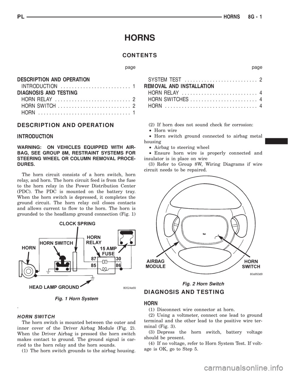
The horn circuit consists of a horn switch, horn
relay, and horn. The horn circuit feed is from the fuse
to the horn relay in the Power Distribution Center
(PDC). The PDC is mounted on the battery tray.
When the horn switch is depressed, it completes the
ground circuit. The horn relay coil closes contacts
and allows current to flow to the horn. The horn is
grounded to the headlamp ground connection (Fig. 1)
.
HORN SWITCH
The horn switch is mounted between the outer and
inner cover of the Driver Airbag Module (Fig. 2).
When the Driver Airbag is pressed the horn switch
makes contact to ground. The ground signal is car-
ried to the horn relay and the horn sounds.
(1) The horn switch grounds to the airbag housing.(2) If horn does not sound check for corrosion:
²Horn wire
²Horn switch ground connected to airbag metal
housing
²Airbag to steering wheel
²Ensure horn wire is properly connected and
insulator is in place on wire
(3) Refer to Group 8W, Wiring Diagrams if wire
circuit needs to be repaired.
DIAGNOSIS AND TESTING
HORN
(1) Disconnect wire connector at horn.
(2) Using a voltmeter, connect one lead to ground
terminal and the other lead to the positive wire ter-
minal (Fig. 3).
(3) Depress the horn switch, battery voltage
should be present.
(4) If no voltage, refer to Horn System Test. If volt-
age is OK, go to Step 5.
Fig. 1 Horn System
Fig. 2 Horn Switch
PLHORNS 8G - 1