Page 914 of 1807
N09783
2
2AEA1II1
IB6 IF219 622
7
1
2
1
BatteryR/B No.2
HAZ-HORNW
(2JZ-GE)Theft Deterrent and
Door Lock ECU T13
(2JZ-GE)
11
(2JZ-GTE)
Theft Deterrent
Horn (2JZ-GTE)
BP-B W
WW-LW-L
SHa
b P-B
W-L
- DIAGNOSTICSTHEFT DETERRENT SYSTEM
DI-623
851 Author�: Date�:
1997 SUPRA (RM502U)
Theft Deterrent Horn Circuit
CIRCUIT DESCRIPTION
When the theft deterrent system is activated, contact ºaº and contact ºbº in the ECU close alternately in cycles
of approximately 0.2 sec., causing the theft deterrent horn to blow (See the wiring diagram below).
In this condition, if any of the following operations is done, the contact ºaº in the ECU opens, thus stopping
the theft deterrent horn from blowing:
(1) The front LH or RH door is unlocked with a key.
(2) The ignition switch is turned to the ACC or ON position.
(3) Approximately 1 minute elapses.
WIRING DIAGRAM
DI4X4-01
Page 917 of 1807
*1
HEAD
(LH-L WR)*2HEAD R/B No.2
FL MAIN
Light Control
Switch
R/B No.2
HEAD
(RH)*1
HEAD
(RH-L WR)*2R-")
I02543
Theft Deterrent and
Door Lock ECU
*1: USA Models
*2: CANADA Models BatteryR/B No.2
HEAD
(LH)*1
HEAD
(LH-L WR)*2HEAD R/B No.2
FL MAIN
Light Control
Switch
R/B No.2
HEAD
(RH)*1
HEAD
(RH-L WR)*2R-Y R-Y R-Y R-Y
R-G R-B
W-B
W-B BRR 2
2
2
22
22
2
11 1 1
4
23
10 16 13
IB2
IF2 2A
EA Headlight Relay
T13
DI-626
- DIAGNOSTICSTHEFT DETERRENT SYSTEM
854 Author�: Date�:
1997 SUPRA (RM502U)
Headlight Control Relay Circuit
CIRCUIT DESCRIPTION
When the theft deterrent system is activated, it causes the Tr in the ECU to switch on and off at approximately
0.2 sec. intervals. This switches the headlight control relay on and off, thus flashing the headlights (See the
wiring diagram below).
In this condition, if any of the following operations is done, the Tr in the ECU goes off and the headlight control
relay switches off, thus stopping the headlights flashing:
(1) The front LH or RH door is unlocked with a key.
(2) The ignition switch is turned to the ACC or ON position.
(3) Approximately 1 minute elapses.
WIRING DIAGRAM
DI4X5-01
Page 919 of 1807

I02545
I02545
Theft Deterrent and
Door Lock ECUT13
IF2
2 2
2A22 J/B No.1
1B 1K
1C
LG LGG-W G-W
G-WTAIL 11
16
3 5TAIL 1 W-L
W-B
Ta i l
Light
W-B
W-B
1
193
B
Battery
Light
Failure
Sensor
Light Control Switch15
23
G
Taillight Control Relay
B1
BJ
ALT
POWER
W
1
5
5 2 DI-628
- DIAGNOSTICSTHEFT DETERRENT SYSTEM
856 Author�: Date�:
1997 SUPRA (RM502U)
Taillight Control Relay Circuit
CIRCUIT DESCRIPTION
When the theft deterrent system is activated, it causes the Tr in the ECU to switch on and off at approximately
0.2 sec. intervals. This switches the taillight control relay on and off, thus the taillights flash (See the wiring
diagram below).
In this condition, if any of the following operations is done, the Tr in the ECU goes off and the taillight control
relay switches off, thus stopping the taillights flashing:
(1) The front LH or RH door is unlocked with a key.
(2) The ignition switch is turned to the ACC or ON position.
(3) Approximately 1 minute elapses.
WIRING DIAGRAM
DI4X6-01
Page 932 of 1807
I02549
Luggage Compartment Door
Key Lock and Unlock SwichTheft Deterrent and Door Lock ECU
LUG
IE1
W-B
BJ
1L4
L
912V T13
2
- DIAGNOSTICSTHEFT DETERRENT SYSTEM
DI-633
861 Author�: Date�:
1997 SUPRA (RM502U)
Luggage Compartment Door Key Lock and Unlock Switch
Circuit
CIRCUIT DESCRIPTION
The luggage compartment door key lock and unlock switch goes on when the back door key cylinder is
turned to the unlock side with the key.
WIRING DIAGRAM
DI4X8-01
Page 933 of 1807
 ON
Connect
I02551
Disconnect
1 2
DI-634
- DIAGNOSTICSTHEFT DETERRENT SYSTEM
862 Author�: Date�:
1997 SUPRA (RM502U)
INSPECTION PROCEDURE
1 Check voltage between terminal 1 of luggage co")
I02550
1 (+) ON
Connect
I02551
Disconnect
1 2
DI-634
- DIAGNOSTICSTHEFT DETERRENT SYSTEM
862 Author�: Date�:
1997 SUPRA (RM502U)
INSPECTION PROCEDURE
1 Check voltage between terminal 1 of luggage compartment door key lock and
unlock switch connector and body ground.
PREPARATION:
(a) Remove deck trim rear cover.
(b) Turn the ignition switch ON.
CHECK:
Measure voltage between terminal 1 of luggage compartment
door key lock and unlock switch connector and body ground,
when the key is turned to the unlock side and not turned.
OK:
Key operationVoltage
Turned to the unlock side0 V
Not turnedBattery positive voltage
OK Check and replace theft deterrent and door lock
ECU. *1
NG
2 Check luggage compartment door key lock and unlock switch.
PREPARATION:
Disconnect luggage compartment door key lock and unlock
switch connector.
CHECK:
Check continuity between terminals 1 and 2, when the key is
turned to the unlock side and not turned.
OK:
Key positionTerminal No. to continuity
Turned to unlock side1 - 2
Not turned-
NG Repair or replace luggage compartment door
key lock and unlock switch.
OK
Page 934 of 1807
- DIAGNOSTICSTHEFT DETERRENT SYSTEM
DI-635
863 Author�: Date�:
1997 SUPRA (RM502U)
3 Check harness and connector between theft deterrent and door lock ECU and
key unlock switch, key unlock switch and body ground (See page IN-28).
NG Repair or replace harness or connector.
OK
Check and replace theft deterrent and door
lock ECU.
*
1: When there is a malfunction that the theft deterrent system cannot be set, proceed to the next numbered
circuit inspection shown on matrix chart (See page DI-615).
Page 947 of 1807
I02566
Door Key Lock and
Unlock Switch LHTheft Deterrent and
Door Lock ECU
Door Key Lock and
Unlock Switch RH J/B No.1
W-B
W-BT13
W-BW-BG-Y
WW
G-Y
G-YG-Y G
UL3
L2
UL2 W12V
12V
1J1
1D 10
IL1 161
2
2
1 33ID1
ID1
IL1
IL1273 13
6
22
16
IE
IH
DI-656
- DIAGNOSTICSTHEFT DETERRENT SYSTEM
884 Author�: Date�:
1997 SUPRA (RM502U)
Door Key Lock and Unlock Switch Circuit
CIRCUIT DESCRIPTION
The door key lock and unlock switch is built in the door key cylinder.
When the key is turned to the lock side, terminal 3 of the switch is grounded and when the key is turned to
the unlock side, terminal 1 of the switch is grounded.
WIRING DIAGRAM
DI4XH-01
Page 948 of 1807
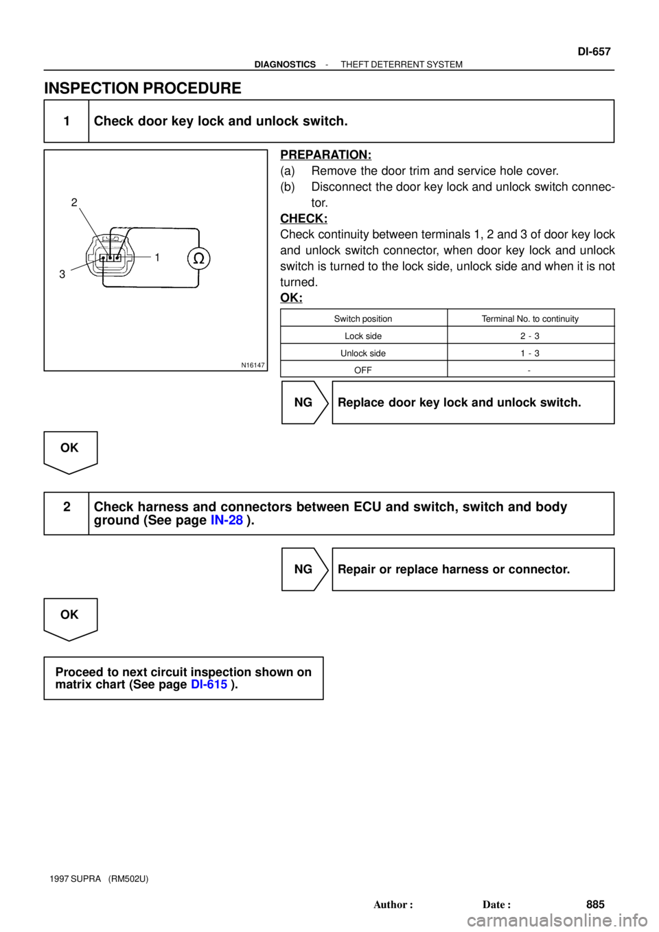
N16147
2
31
- DIAGNOSTICSTHEFT DETERRENT SYSTEM
DI-657
885 Author�: Date�:
1997 SUPRA (RM502U)
INSPECTION PROCEDURE
1 Check door key lock and unlock switch.
PREPARATION:
(a) Remove the door trim and service hole cover.
(b) Disconnect the door key lock and unlock switch connec-
tor.
CHECK:
Check continuity between terminals 1, 2 and 3 of door key lock
and unlock switch connector, when door key lock and unlock
switch is turned to the lock side, unlock side and when it is not
turned.
OK:
Switch positionTerminal No. to continuity
Lock side2 - 3
Unlock side1 - 3
OFF-
NG Replace door key lock and unlock switch.
OK
2 Check harness and connectors between ECU and switch, switch and body
ground (See page IN-28).
NG Repair or replace harness or connector.
OK
Proceed to next circuit inspection shown on
matrix chart (See page DI-615).
Theft Deterrent and
Door Lock ECU T13
(2JZ-GE)
11
(2JZ-GTE)
Theft Deterrent
Horn (2JZ-GTE)
BP-B W
WW-LW-L
SHa
b P-B
W-L
- DIAG")