Page 378 of 1807

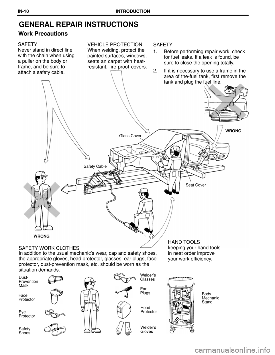
GENERAL REPAIR INSTRUCTIONS
Work Precautions
VEHICLE PROTECTION
When welding, protect the
painted surfaces, windows,
seats an carpet with heat-
resistant, fire-proof covers.SAFETY
1. Before performing repair work, check
for fuel leaks. If a leak is found, be
sure to close the opening totally.
2. If it is necessary to use a frame in the
area of the-fuel tank, first remove the
tank and plug the fuel line. SAFETY
Never stand in direct line
with the chain when using
a puller on the body or
frame, and be sure to
attach a safety cable.
WRONG
Glass Cover
Safety Cable
Seat Cover
WRONG
HAND TOOLS
keeping your hand tools
in neat order improve
your work efficiency. SAFETY WORK CLOTHES
In addition to the usual mechanic's wear, cap and safety shoes,
the appropriate gloves, head protector, glasses, ear plugs, face
protector, dust-prevention mask, etc. should be worn as the
situation demands.
Dust-
Prevention
Mask.Welder's
Glasses
Ear
Plugs
Body
Mechanic
Stand Face
Protector
Head
Protector
Eye
Protector
Welder's
Gloves Safety
Shoes
INTRODUCTIONIN-10
Page 1286 of 1807
EM0AI-02
P12293
P02267
P12308SST EM-34
- ENGINE MECHANICAL (2JZ-GTE)CYLINDER HEAD
1139 Author�: Date�:
1997 SUPRA (RM502U)
DISASSEMBLY
1. REMOVE ENGINE HANGERS AND GROUND STRAP
2. REMOVE CAMSHAFT POSITION SENSORS
3. REMOVE EGR COOLER
4. REMOVE VALVE LIFTERS AND SHIMS
HINT:
Store the valve lifters and shims in correct order.
5. REMOVE VALVES
(a) Using SST, compress the valve spring and remove the 2
keepers.
SST 09202-70020 (09202-00010)
(b) Remove the spring retainer, valve spring, valve and
spring seat.
HINT:
Store the valves, valve springs, spring seats and spring retain-
ers in correct order.
(c) Using needle-nose pliers, remove the oil seal.
Page 1290 of 1807

EM2534
Overall Length
EM0255
P02127
45°
Carbide
Cutter
Z00373
Width
P03966
45°
15°
Width EM-38
- ENGINE MECHANICAL (2JZ-GTE)CYLINDER HEAD
1143 Author�: Date�:
1997 SUPRA (RM502U)
(d) Check the valve overall length.
Standard overall length:
Intake 98.29 - 98.79 mm (3.8697 - 3.8894 in.)
Exhaust 98.84 - 99.34 mm (3.8913 - 3.9110 in.)
Minimum overall length:
Intake 98.19 mm (3.8657 in.)
Exhaust 98.74 mm (3.8874 in.)
If the overall length is less than minimum, replace the valve.
(e) Check the surface of the valve stem tip for wear.
If the valve stem tip is worn, resurface the tip with a grinder or
replace the valve.
NOTICE:
Do not grind off more than the minimum overall length.
11. INSPECT AND CLEAN VALVE SEATS
(a) Using a 45° carbide cutter, resurface the valve seats.
Remove only enough metal to clean the seats.
(b) Check the valve seating position.
Apply a thin coat of prussian blue (or white lead) to the
valve face. Lightly press the valve against the seat. Do not
rotate the valve.
(c) Check the valve face and seat for the following:
�If blue appears 360° around the face, the valve is
concentric. If not, replace the valve.
�If blue appears 360° around the valve seat, the
guide and face are concentric. If not, resurface the
seat.
�Check that the seat contact is in the middle of the
valve face with the following width:
Intake 1.0 - 1.4 mm (0.039 - 0.055 in.)
Exhaust 1.2 - 1.6 mm (0.047 - 0.063 in.)
If not, correct the valve seats as follows:
�If the seating is too high on the valve face, use 15°
and 45° cutters to correct the seat.
Page 1608 of 1807

SR14B-01
R06961
SST
R07510
SST
SR4371Matchmarks
Z06090
Chisel
R07107SST
- STEERINGPOWER STEERING GEAR
SR-39
1923 Author�: Date�:
1997 SUPRA (RM502U)
DISASSEMBLY
NOTICE:
When using a vise, do not overtighten it.
1. SECURE PS GEAR ASSEMBLY IN VISE
Using SST, secure the gear assembly in a vise.
SST 09612-00012
2. REMOVE 2 TURN PRESSURE TUBES
(a) Remove the union bolt and 2 gaskets.
(b) Using SST, remove the tube.
SST 09633-00020
(c) Remove the 2 union seats from the rack housing.
3. REMOVE RH AND LH TIE ROD ENDS AND LOCK
NUTS
Place matchmarks on the tie rod end and rack end, and loosen
the lock nut.
4. REMOVE RH AND LH CLIPS, RACK BOOTS AND
CLAMPS
NOTICE:
�Be careful not to damage the boot.
�Mark the RH and LH boots.
5. REMOVE RH AND LH RACK ENDS AND CLAW WASH-
ERS
(a) Using a chisel and a hammer, unstake the washer.
NOTICE:
Avoid any impact to the steering rack.
(b) Using a spanner (22 mm) to hold the steering rack and us-
ing SST, remove the rack end.
SST 09922-10010
NOTICE:
�Use SST 09922-10010 in the direction shown in the il-
lustration.
�Mark the RH and LH rack ends.