Page 82 of 1807

GLOSSARY OF SAE AND TOYOTA TERMS
This glossary lists all SAE-J1930 terms and abbreviations used in this manual in compliance")
IN04J-01
- INTRODUCTIONTERMS
IN-35
35 Author�: Date�:
1997 SUPRA (RM502U)
GLOSSARY OF SAE AND TOYOTA TERMS
This glossary lists all SAE-J1930 terms and abbreviations used in this manual in compliance with SAE rec-
ommendations, as well as their Toyota equivalents.
SAE
ABBREVIATIONSSAE TERMSTOYOTA TERMS
( )--ABBREVIATIONS
A/CAir ConditioningAir Conditioner
ACLAir CleanerAir Cleaner
AIRSecondary Air InjectionAir Injection (AI)
APAccelerator Pedal-
B+Battery Positive Voltage+B, Battery Voltage
BAROBarometric Pressure-
CACCharge Air CoolerIntercooler
CARBCarburetorCarburetor
CFIContinuous Fuel Injection-
CKPCrankshaft PositionCrank Angle
CLClosed LoopClosed Loop
CMPCamshaft PositionCam Angle
CPPClutch Pedal Position-
CTOXContinuous Trap Oxidizer-
CTPClosed Throttle Position-
DFIDirect Fuel Injection (Diesel)Direct Injection (DI)
DIDistributor Ignition-
DLC1
DLC2
DLC3Data Link Connector 1
Data Link Connector 2
Data Link Connector 31: Check Connector
2: Total Diagnosis Comunication Link (TDCL)
3: OBD II Diagnostic Connector
DTCDiagnostic Trouble CodeDiagnostic Code
DTMDiagnostic Test Mode-
ECLEngine Control Level-
ECMEngine Control ModuleEngine ECU (Electronic Control Unit)
ECTEngine Coolant TemperatureCoolant Temperature, Water Temperature (THW)
EEPROMElectrically Erasable Programmable Read Only Memory
Electrically Erasable Programmable Read Only Memory
(EEPROM),
Erasable Programmable Read Only Memory (EPROM)
EFEEarly Fuel EvaporationCold Mixture Heater (CMH), Heat Control Valve (HCV)
EGRExhaust Gas RecirculationExhaust Gas Recirculation (EGR)
EIElectronic IgnitionDistributorless Ignition (DI)
EMEngine ModificationEngine Modification (EM)
EPROMErasable Programmable Read Only MemoryProgrammable Read Only Memory (PROM)
EVAPEvaporative EmissionEvaporative Emission Control (EVAP)
FCFan Control-
FEEPROMFlash Electrically Erasable Programmable
Read Only Memory-
FEPROMFlash Erasable Programmable Read Only Memory-
FFFlexible Fuel-
FPFuel PumpFuel Pump
GENGeneratorAlternator
GNDGroundGround (GND)
Page 117 of 1807
AC0Q2-01
Z18473
Pressure Switch
ReceiverRadiator
Fan Relay
No. 1
Compressor
Radiator
Fan Relay
No. 2Junction Block No. 2
� Magnetic Clutch Relay
� Reater Main Relay
Ambient Temperature
Sensor
Air Conditioning Amplifier
Solar Sensor
Room Temperature
SensorAir Conditioning
Control Assembly
Evaporator
Expansion Valve
Water Valve
Heater Radiaor
Air Outlet ServomotorAir Inlet
Servomotor
Blower Motor
Blower Motor
Control Relay
Evaporator Temperature Sensor
Air Mix Servomotor
Engine Coolant Temperature Sensor AC-14
- AIR CONDITIONINGAIR CONDITIONING SYSTEM
2162 Author�: Date�:
1997 SUPRA (RM502U)
LOCATION
Page 123 of 1807
N11671
Defroster Nozzle
Water Valve CoverPlate
Water Valve
Heater Radiator
A/C Unit
Block Joint
Blower Motor
Control Relay
Blower Motor
Lower CaseEvaporator
Expansion
Valve Air Inlet
Servomotor
Evaporator Temperature
Sensor Heater Air Duct
Evaporator CoverVent Air DuctEngine Coolant
Temperature
SensorAir Outlet
ServomotorAir Mix
Servomotor AC-24
- AIR CONDITIONINGAIR CONDITIONING UNIT
2172 Author�: Date�:
1997 SUPRA (RM502U)
Page 127 of 1807
N08403
AC-28
- AIR CONDITIONINGAIR CONDITIONING UNIT
2176 Author�: Date�:
1997 SUPRA (RM502U)
6. REMOVE HEATER RADIATOR AND WATER VALVE
(a) Remove the 2 screws and the plate.
(b) Remove the 2 screws and the clamp.
(c) Remove the 3 screws.
(d) Pull out the heater radiator with the water valve.
(e) Remove the 2 screws and water valve from the heater ra-
diator.
7. REMOVE HEATER AIR DUCT
Remove the 2 screws and the defroster air duct.
8. REMOVE AIR VENT DUCT
(a) Disconnect the control link.
(b) Remove the 2 screws and the vent air duct.
9. REMOVE ENGINE COOLANT TEMPERATURE SEN-
SOR
(a) Disconnect the connector.
(b) After pulling off the clamp, pull out the sensor.
10. REMOVE AIR OUTLET SERVOMOTOR
(a) Disconnect the connector.
(b) Remove the 3 screws and the air outlet servomotor.
Page 150 of 1807
N08382
N08399
AC-70
- AIR CONDITIONINGSENSOR
2218 Author�: Date�:
1997 SUPRA (RM502U)
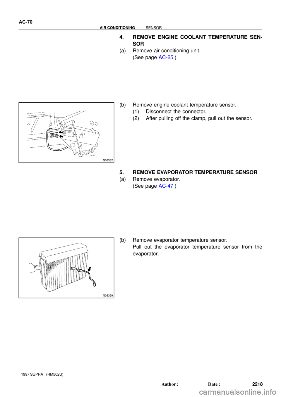
4. REMOVE ENGINE COOLANT TEMPERATURE SEN-
SOR
(a) Remove air conditioning unit.
(See page AC-25)
(b) Remove engine coolant temperature sensor.
(1) Disconnect the connector.
(2) After pulling off the clamp, pull out the sensor.
5. REMOVE EVAPORATOR TEMPERATURE SENSOR
(a) Remove evaporator.
(See page AC-47)
(b) Remove evaporator temperature sensor.
Pull out the evaporator temperature sensor from the
evaporator.
Page 155 of 1807
I03527
AC0RQ-01
- AIR CONDITIONINGENGINE COOLANT TEMPERATURE (ECT) SWITCH
AC-85
2233 Author�: Date�:
1997 SUPRA (RM502U)
ENGINE COOLANT
TEMPERATURE (ECT) SWITCH
REMOVAL
1. REMOVE ENGINE UNDER COVER
2. DRAIN ENGINE COOLANT
HINT:
It is not necessary to drain out all coolant.
3. REMOVE SWITCH
(a) Disconnect the connector.
(b) Remove the switch.
Torque: 7.4 N´m (75 kgf´cm, 65 in.´lbf)
HINT:
At the time of installation, please refer to the following item.
Lubricate a new O-ring with soapy water and install the switch.
Page 156 of 1807
P01924
AC0RR-01
AC-86
- AIR CONDITIONINGENGINE COOLANT TEMPERATURE (ECT) SWITCH
2234 Author�: Date�:
1997 SUPRA (RM502U)
INSPECTION
INSPECT ECT SWITCH CONTINUITY
(a) Using an ohmmeter, check the no continuity exists be-
tween the terminals when the coolant temperature is a
above 100°C (212°F).
If there is continuity, replace the switch.
(b) Using an ohmmeter, check the continuity existsbetween
the terminals when the coolant temperature is below
91°C (196°F).
If there is no continuity, replace the switch.
Page 162 of 1807

WIPER AND WASHER SYSTEM
SymptomSuspect AreaSee page
Wipers and washers do not operate.
1. WIPER Fuse (J/B No.1)")
BE-6
- BODY ELECTRICALBODY ELECTRICAL SYSTEM
1984 Author�: Date�:
1997 SUPRA (RM502U)
WIPER AND WASHER SYSTEM
SymptomSuspect AreaSee page
Wipers and washers do not operate.
1. WIPER Fuse (J/B No.1)
2. Ignition Switch
3. Wiper and Washer Switch
4. Wire Harness
BE-13
BE-35
Front wiper does not operate.
1. Front Wiper and Washer Switch
2. Front Wiper Motor
3. Wire HarnessBE-35
BE-35
Rear wiper does not operate.
1. Rear Wiper and Washer Switch
2. Rear Wiper Motor and Relay
3. Wire HarnessBE-35
BE-35
Front washer does not operate.
1. Front Wiper and Washer Switch
2. Washer Motor
3. Wire HarnessBE-35
BE-35
Rear washer does not operate.
1. Rear Wiper and Washer Switch
2. Washer Motor
3. Wire HarnessBE-35
BE-35
COMBINATION METER
METER, GAUGES AND ILLUMINATION:
SymptomSuspect AreaSee page
Tachometer, Fuel Gauge and Engine Coolant Temperature
Gauge do not operate.1. GAUGE Fuse (J/B No.1)
2. Meter Circuit
3. Wire Harness
BE-40
Speedometer does not operate.
1. Vehicle Speed Sensor
2. Meter Circuit
3. Wire HarnessBE-43
BE-40
Tachometer does not operate.
1. Igniter
2. ECM
3. Meter Circuit
4. Wire Harness
DI-1
DI-145
BE-40
Fuel Gauge does not operate or abnormal operation.
1. Fuel Receiver Gauge
2. Fuel Sender Gauge
3. Meter Circuit
4. Wire HarnessBE-43
BE-43
BE-40
Engine Coolant Temperature Gauge does not operate or
abnormal operation.
1. Engine Coolant Temperature Receiver Gauge
2. Engine Coolant Temperature Sender Gauge
3. Meter Circuit
4. Wire HarnessBE-43
BE-43
BE-40
All illumination lights do not light up.
1. TAIL Fuse (J/B No.1)
2. Light Control Rheostat
3. Meter Circuit
4. Wire Harness
BE-43
BE-40
Only one illumination light does not light up.1. Bulb
2. Meter Circuit
BE-40