Page 71 of 1807

� DTC No.
Indicates the diagnostic trouble code.
� Page or Instructions
Indicates the page where the inspection procedure
for each circuit is to be found, or gives instructions
for checking and repairs.
� Detection Item
Indicates the system of the problem or
contents of the problem.� Trouble Area
Indicates the suspect area of the
problem.
Mass Air Flow Circuit MalfunctionDetection Item
� Open or short in mass air flow meter circuit
� Mass air flow meter
� ECM DTC No.
(See page)Trouble AreaMIL*MemoryP0100
(DI-23)
P0101
(DI-27)Mass Air Flow Circuit
Range/Performance Problem� Mass air flow meter
P0115
(DI-32)� Open or short in intake air temp. sensor circuit
� Intake air temp. sensor
� ECM Intake Air Temp. Circuit Malfunction P0110
(DI-28)
Engine Coolant Temp. Circuit
Range/Performance Problem� Open or short in engine coolant temp. sensor circuit
� Engine coolant temp. sensor
� ECM
P0120
(DI-37)
Throttle/ Pedal Position Sensor/Switch
ºAº Circuit Range/Performance
P0116
(DI-36)
Throttle/Pedal Position Sensor/Switch
ºAº Circuit Malfunction
Insufficient Coolant Temp. for Closed� Engine coolant temp. sensor
� Cooling system Engine Coolant Temp. Circuit
Malfunction
� Open or short in throttle position sensor circuit
� Throttle position sensor
� ECM
� Throttle position sensor
� Open or short in heated oxygen sensor circuit
� Heated oxygen sensor
DTC CHART (SAE Controlled)
HINT: Parameters listed in the chart may not be exactly the same as your reading due to the type of instrument
or other factors.
If a malfunction code is displayed during the DTC check mode, check the circuit for that code listed in the table
below. For details of each code, turn to the page referred to under the ºSee pageº for the respective ºDTC No.º
in the DTC chart.
IN-24- INTRODUCTIONHOW TO TROUBLESHOOT ECU CONTROLLED
SYSTEMS
24 Author�: Date�:
1997 SUPRA (RM502U)
4. DIAGNOSTIC TROUBLE CODE CHART
The inspection procedure is shown in the table below. This table permits efficient and accurate troubleshoot-
ing using the diagnostic trouble codes displayed in the diagnostic trouble code check. Proceed with trouble-
shooting in accordance with the inspection procedure given in the diagnostic chart corresponding to the
diagnostic trouble codes displayed. The engine diagnostic trouble code chart is shown below as an example.
Page 82 of 1807

GLOSSARY OF SAE AND TOYOTA TERMS
This glossary lists all SAE-J1930 terms and abbreviations used in this manual in compliance")
IN04J-01
- INTRODUCTIONTERMS
IN-35
35 Author�: Date�:
1997 SUPRA (RM502U)
GLOSSARY OF SAE AND TOYOTA TERMS
This glossary lists all SAE-J1930 terms and abbreviations used in this manual in compliance with SAE rec-
ommendations, as well as their Toyota equivalents.
SAE
ABBREVIATIONSSAE TERMSTOYOTA TERMS
( )--ABBREVIATIONS
A/CAir ConditioningAir Conditioner
ACLAir CleanerAir Cleaner
AIRSecondary Air InjectionAir Injection (AI)
APAccelerator Pedal-
B+Battery Positive Voltage+B, Battery Voltage
BAROBarometric Pressure-
CACCharge Air CoolerIntercooler
CARBCarburetorCarburetor
CFIContinuous Fuel Injection-
CKPCrankshaft PositionCrank Angle
CLClosed LoopClosed Loop
CMPCamshaft PositionCam Angle
CPPClutch Pedal Position-
CTOXContinuous Trap Oxidizer-
CTPClosed Throttle Position-
DFIDirect Fuel Injection (Diesel)Direct Injection (DI)
DIDistributor Ignition-
DLC1
DLC2
DLC3Data Link Connector 1
Data Link Connector 2
Data Link Connector 31: Check Connector
2: Total Diagnosis Comunication Link (TDCL)
3: OBD II Diagnostic Connector
DTCDiagnostic Trouble CodeDiagnostic Code
DTMDiagnostic Test Mode-
ECLEngine Control Level-
ECMEngine Control ModuleEngine ECU (Electronic Control Unit)
ECTEngine Coolant TemperatureCoolant Temperature, Water Temperature (THW)
EEPROMElectrically Erasable Programmable Read Only Memory
Electrically Erasable Programmable Read Only Memory
(EEPROM),
Erasable Programmable Read Only Memory (EPROM)
EFEEarly Fuel EvaporationCold Mixture Heater (CMH), Heat Control Valve (HCV)
EGRExhaust Gas RecirculationExhaust Gas Recirculation (EGR)
EIElectronic IgnitionDistributorless Ignition (DI)
EMEngine ModificationEngine Modification (EM)
EPROMErasable Programmable Read Only MemoryProgrammable Read Only Memory (PROM)
EVAPEvaporative EmissionEvaporative Emission Control (EVAP)
FCFan Control-
FEEPROMFlash Electrically Erasable Programmable
Read Only Memory-
FEPROMFlash Erasable Programmable Read Only Memory-
FFFlexible Fuel-
FPFuel PumpFuel Pump
GENGeneratorAlternator
GNDGroundGround (GND)
Page 117 of 1807
AC0Q2-01
Z18473
Pressure Switch
ReceiverRadiator
Fan Relay
No. 1
Compressor
Radiator
Fan Relay
No. 2Junction Block No. 2
� Magnetic Clutch Relay
� Reater Main Relay
Ambient Temperature
Sensor
Air Conditioning Amplifier
Solar Sensor
Room Temperature
SensorAir Conditioning
Control Assembly
Evaporator
Expansion Valve
Water Valve
Heater Radiaor
Air Outlet ServomotorAir Inlet
Servomotor
Blower Motor
Blower Motor
Control Relay
Evaporator Temperature Sensor
Air Mix Servomotor
Engine Coolant Temperature Sensor AC-14
- AIR CONDITIONINGAIR CONDITIONING SYSTEM
2162 Author�: Date�:
1997 SUPRA (RM502U)
LOCATION
Page 123 of 1807
N11671
Defroster Nozzle
Water Valve CoverPlate
Water Valve
Heater Radiator
A/C Unit
Block Joint
Blower Motor
Control Relay
Blower Motor
Lower CaseEvaporator
Expansion
Valve Air Inlet
Servomotor
Evaporator Temperature
Sensor Heater Air Duct
Evaporator CoverVent Air DuctEngine Coolant
Temperature
SensorAir Outlet
ServomotorAir Mix
Servomotor AC-24
- AIR CONDITIONINGAIR CONDITIONING UNIT
2172 Author�: Date�:
1997 SUPRA (RM502U)
Page 124 of 1807
AC0QC-01
N08378
I03519
- AIR CONDITIONINGAIR CONDITIONING UNIT
AC-25
2173 Author�: Date�:
1997 SUPRA (RM502U)
REMOVAL
1. DISCHARGE REFRIGERANT FROM REFRIGERANT
SYSTEM
HINT:
At the time of installation, please refer to the following item.
Evacuate air from refrigeration system.
Charge system with the refrigerant and inspect for leakage of
refrigerant.
Specified amount: 700 ± 50 g (24.96 ± 1.76 oz.)
2. DRAIN ENGINE COOLANT FROM RADIATOR
HINT:
It is not necessary to drain out all coolant.
3. REMOVE THESE PARTS:
(a) Engine wire harness bracket mounting bolt
(b) Brake tube bracket mounting bolts
4. DISCONNECT WATER HOSE FROM HEATER RADIA-
TOR PIPES
(a) Using priers, grip the claw of the hose clip and slide the
clip along the hose.
(b) Disconnect the water hoses from heater radiator pipes.
5. REMOVE INSULATOR RETAINER
Remove the 2 bolts and the insulator retainer.
Page 127 of 1807
N08403
AC-28
- AIR CONDITIONINGAIR CONDITIONING UNIT
2176 Author�: Date�:
1997 SUPRA (RM502U)
6. REMOVE HEATER RADIATOR AND WATER VALVE
(a) Remove the 2 screws and the plate.
(b) Remove the 2 screws and the clamp.
(c) Remove the 3 screws.
(d) Pull out the heater radiator with the water valve.
(e) Remove the 2 screws and water valve from the heater ra-
diator.
7. REMOVE HEATER AIR DUCT
Remove the 2 screws and the defroster air duct.
8. REMOVE AIR VENT DUCT
(a) Disconnect the control link.
(b) Remove the 2 screws and the vent air duct.
9. REMOVE ENGINE COOLANT TEMPERATURE SEN-
SOR
(a) Disconnect the connector.
(b) After pulling off the clamp, pull out the sensor.
10. REMOVE AIR OUTLET SERVOMOTOR
(a) Disconnect the connector.
(b) Remove the 3 screws and the air outlet servomotor.
Page 144 of 1807
AC0R1-01
N19660
- AIR CONDITIONINGWATER VALVE
AC-57
2205 Author�: Date�:
1997 SUPRA (RM502U)
WATER VALVE
REMOVAL
1. DRAIN ENGINE COOLANT FROM RADIATOR
HINT:
It is not to drain out all coolant.
2. REMOVE INSTRUMENT PANEL
(See page BO-54)
3. REMOVE AIR MIX SERVOMOTOR
(See page AC-65)
4. REMOVE WATER VALVE
Remove the 5 screws and water valve.
Page 150 of 1807
N08382
N08399
AC-70
- AIR CONDITIONINGSENSOR
2218 Author�: Date�:
1997 SUPRA (RM502U)
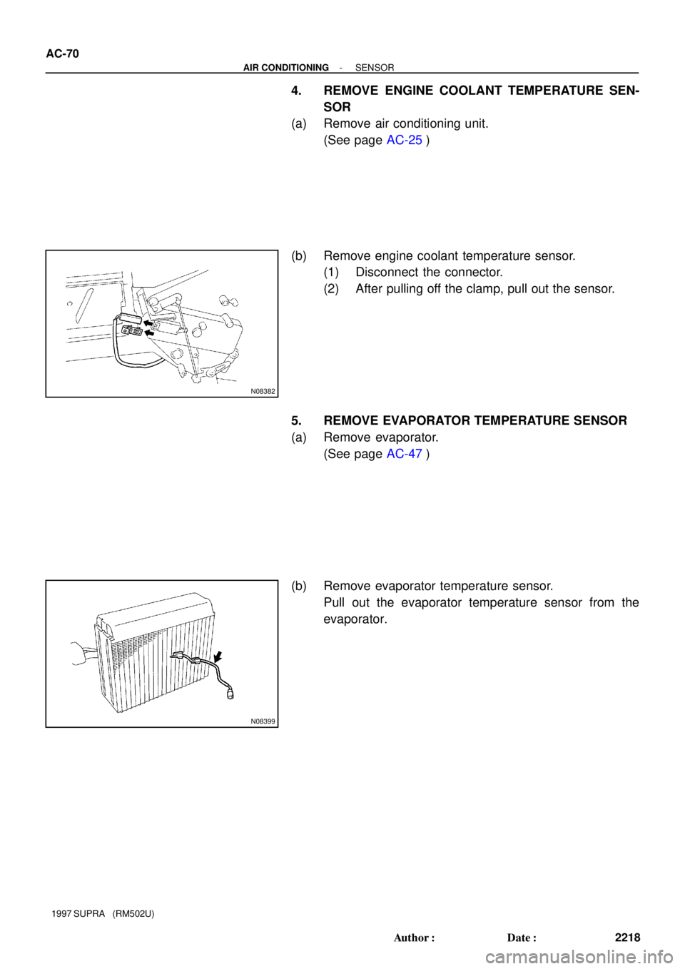
4. REMOVE ENGINE COOLANT TEMPERATURE SEN-
SOR
(a) Remove air conditioning unit.
(See page AC-25)
(b) Remove engine coolant temperature sensor.
(1) Disconnect the connector.
(2) After pulling off the clamp, pull out the sensor.
5. REMOVE EVAPORATOR TEMPERATURE SENSOR
(a) Remove evaporator.
(See page AC-47)
(b) Remove evaporator temperature sensor.
Pull out the evaporator temperature sensor from the
evaporator.