Page 155 of 1807
I03527
AC0RQ-01
- AIR CONDITIONINGENGINE COOLANT TEMPERATURE (ECT) SWITCH
AC-85
2233 Author�: Date�:
1997 SUPRA (RM502U)
ENGINE COOLANT
TEMPERATURE (ECT) SWITCH
REMOVAL
1. REMOVE ENGINE UNDER COVER
2. DRAIN ENGINE COOLANT
HINT:
It is not necessary to drain out all coolant.
3. REMOVE SWITCH
(a) Disconnect the connector.
(b) Remove the switch.
Torque: 7.4 N´m (75 kgf´cm, 65 in.´lbf)
HINT:
At the time of installation, please refer to the following item.
Lubricate a new O-ring with soapy water and install the switch.
Page 156 of 1807
P01924
AC0RR-01
AC-86
- AIR CONDITIONINGENGINE COOLANT TEMPERATURE (ECT) SWITCH
2234 Author�: Date�:
1997 SUPRA (RM502U)
INSPECTION
INSPECT ECT SWITCH CONTINUITY
(a) Using an ohmmeter, check the no continuity exists be-
tween the terminals when the coolant temperature is a
above 100°C (212°F).
If there is continuity, replace the switch.
(b) Using an ohmmeter, check the continuity existsbetween
the terminals when the coolant temperature is below
91°C (196°F).
If there is no continuity, replace the switch.
Page 162 of 1807

BE-6
- BODY ELECTRICALBODY ELECTRICAL SYSTEM
1984 Author�: Date�:
1997 SUPRA (RM502U)
WIPER AND WASHER SYSTEM
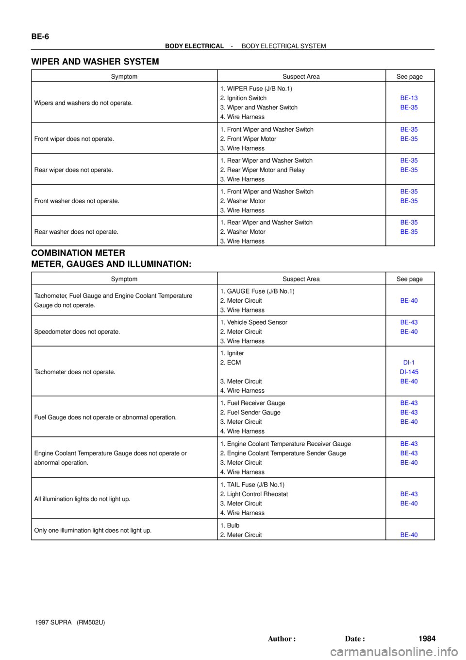
SymptomSuspect AreaSee page
Wipers and washers do not operate.
1. WIPER Fuse (J/B No.1)
2. Ignition Switch
3. Wiper and Washer Switch
4. Wire Harness
BE-13
BE-35
Front wiper does not operate.
1. Front Wiper and Washer Switch
2. Front Wiper Motor
3. Wire HarnessBE-35
BE-35
Rear wiper does not operate.
1. Rear Wiper and Washer Switch
2. Rear Wiper Motor and Relay
3. Wire HarnessBE-35
BE-35
Front washer does not operate.
1. Front Wiper and Washer Switch
2. Washer Motor
3. Wire HarnessBE-35
BE-35
Rear washer does not operate.
1. Rear Wiper and Washer Switch
2. Washer Motor
3. Wire HarnessBE-35
BE-35
COMBINATION METER
METER, GAUGES AND ILLUMINATION:
SymptomSuspect AreaSee page
Tachometer, Fuel Gauge and Engine Coolant Temperature
Gauge do not operate.1. GAUGE Fuse (J/B No.1)
2. Meter Circuit
3. Wire Harness
BE-40
Speedometer does not operate.
1. Vehicle Speed Sensor
2. Meter Circuit
3. Wire HarnessBE-43
BE-40
Tachometer does not operate.
1. Igniter
2. ECM
3. Meter Circuit
4. Wire Harness
DI-1
DI-145
BE-40
Fuel Gauge does not operate or abnormal operation.
1. Fuel Receiver Gauge
2. Fuel Sender Gauge
3. Meter Circuit
4. Wire HarnessBE-43
BE-43
BE-40
Engine Coolant Temperature Gauge does not operate or
abnormal operation.
1. Engine Coolant Temperature Receiver Gauge
2. Engine Coolant Temperature Sender Gauge
3. Meter Circuit
4. Wire HarnessBE-43
BE-43
BE-40
All illumination lights do not light up.
1. TAIL Fuse (J/B No.1)
2. Light Control Rheostat
3. Meter Circuit
4. Wire Harness
BE-43
BE-40
Only one illumination light does not light up.1. Bulb
2. Meter Circuit
BE-40
Page 195 of 1807
Z18230
Brake Fluid Level Warning Switch
Parking Brake Switch
Telltale Light LH
Telltale Light RHVehicle Speed Sensor
Light Failure Sensor
DOME Fuse
Combination Meter
Door Courtesy Switches GAUGE Fuse
ECU-B Fuse
IGN Fuse
PANEL Fuse
TAIL Fuse Integration
Fuel Sender Gauge
: Engine Coolant Temperature Sensor
: Engine Oil Level Sensor
: Low Oil Pressure Warning Switch
: Park/Neutral Position Switch
: Vehicle Speed Sensor 2JZ-GE2JZ-GTE
1
5
4
3
2 Relay� R/B No.2
J/B No.1
Meter Circuit �
�
�
�
�
�
1
1
5 4
3
2 1
2
3
4
5
BE0E7-01
- BODY ELECTRICALCOMBINATION METER
BE-39
2017 Author�: Date�:
1997 SUPRA (RM502U)
COMBINATION METER
LOCATION
Page 197 of 1807

I02078
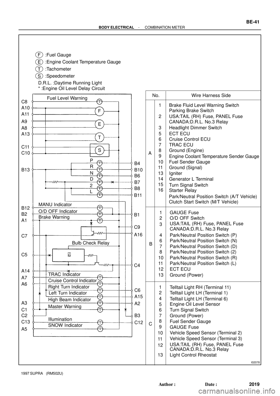
Cruise Control Indicator :Fuel Gauge
:Engine Coolant Temperature Gauge
:Tachometer
:Speedometer
D.R.L. :Daytime Running Light
* :Engine Oil Level Delay Circuit
F
E
T
S
F
E
T
S C8
A10
A11
A9
A8
A13
C11
C10
B13
B12
B2
A1
C7
C5
A14
A7
A6
A3
C1
C2
C13
A5P
R
N
D
2
LB4
B10
B6
B7
B8
B11
B1
C9
A16
C4
C6
A15
A2
B3
C12 Fuel Level Warning
MANU Indicator
O/D OFF Indicator
Brake Warning
Bulb Check Relay
TRAC Indicator
Right Turn Indicator
High Beam Indicator
Master Warning
Illumination
SNOW IndicatorLeft Turn Indicator
No. Wire Harness Side
Brake Fluid Level Warning Switch
Parking Brake Switch
USA:TAIL (RH) Fuse, PANEL Fuse
Headlight Dimmer Switch
ECT ECU
Cruise Control ECU
TRAC ECU
Ground (Engine)
Engine Coolant Temperature Sender Gauge
Fuel Sender Gauge
Ground (Signal)
Turn Signal Switch
Starter Relay Generator L Terminal Igniter
Park/Neutral Position Switch (A/T Vehicle) A1
2
3
5
6
7
8
9
10
11
13
14
15
16
BGAUGE Fuse
O/D OFF Switch
USA:TAIL (RH) Fuse, PANEL Fuse
Park/Neutral Position Switch (P)
Park/Neutral Position Switch (N)
ECT ECU
Ground (Power)
Park/Neutral Position Switch (D)
Park/Neutral Position Switch (2)
Park/Neutral Position Switch (L) Park/Neutral Position Switch (R) 1
2
3
6
7
8
10
11
124
13
Engine Oil Level Sensor
Turn Signal Switch
Ground (Power)
Fuel Sender Gauge
GAUGE Fuse
Vehicle Speed Sensor (Terminal 2)
Vehicle Speed Sensor (Terminal 3)
USA:TAIL (RH) Fuse, PANEL Fuse
Light Control Rheostat Telltail Light RH (Terminal 11)
Telltail Light LH (Terminal 1)
Telltail Light LH (Terminal 6) 1
2
6
7
8
10
11
124
135
9 CCANADA:D.R.L. No.3 Relay
Clutch Start Switch (M/T Vehicle)
CANADA:D.R.L. No.3 Relay
CANADA:D.R.L. No.3 Relay
- BODY ELECTRICALCOMBINATION METER
BE-41
2019 Author�: Date�:
1997 SUPRA (RM502U)
Page 202 of 1807

Z07423
Ignition
Switch
Battery Engine Coolant Temperature Gauge
Sender
Gauge
Z14747
Battery Engine Coolant Temperature Gauge
Test Bulb
(3W)
Z09421
A
BC
N15887
BE-46
- BODY ELECTRICALCOMBINATION METER
2024 Author�: Date�:
1997 SUPRA (RM502U)
10. INSPECT ENGINE COOLANT TEMPERATURE RE-
CEIVER GAUGE OPERATION
(a) Disconnect the connector from the sender gauge.
(b) Turn the ignition switch ON, check that the receiver gauge
needle indicates COOL.
(c) Ground terminal on the wire harness side connector
through a 3 W test bulb.
(d) Turn the ignition switch ON, check that the bulb lights up
and that the receiver gauge needle moves toward the hot
side.
If operation is as specified, replace the sender gauge.
Then recheck the system.
If operation is not as specified, measure the receiver gauge re-
sistance.
11. INSPECT ENGINE COOLANT TEMPERATURE RE-
CEIVER GAUGE RESISTANCE
Measure the resistance between terminals.
HINT:
Connect the test leads so that the current from the ohmmeter
can flow according to the chart order.
Between terminalsResistance (W)
A - BApprox. 229.7
A - CApprox. 54.0
B - CApprox. 175.7
If resistance value is not as specified, replace the engine cool-
ant temperature receiver gauge.
12. INSPECT ENGINE COOLANT TEMPERATURE SEND-
ER GAUGE RESISTANCE
Measure the resistance between terminal and gauge body.
Temperature °C (°F)Resistance (W)
50 (122.0)160 ~ 240
120 (248.0)17.1 ~ 21.2
If resistance value is not as specified, replace the engine cool-
ant temperature sender gauge.
Page 251 of 1807

28 Noise NOISE PRODUCED BY VIBRATION OR SHOCK WHILE DRIVING
No
Ye s Is speaker properly installed?
Noise is produced from static electricity accumulating in the vehicle body. With vehicles stationary lightly tap each system.
Is noise produced?Install properly.
Each system faulty. Is speaker properly installed?
No
No Ye s
Ye s
29 Noise NOISE PRODUCED WHEN ENGINE STARTS
NoYe s Whistling noise which becomes high-pitched when
accelerator strongly depressed, disappears shortly
after engine stops.Generator noise.
A/C noise.
Fuel gauge noise.
Horn noise.
Ignition noise.
Turn signal noise.
Washer noise.
Engine coolant temp. gauge noise.
Wiper noise. Whining noise occurs when A/C is operating.
Scratching noise occurs during sudden acceleration, driving on rough
roads or when ignition switch is turned ON.
Clicking sound is heard when horn button is pressed, then
released. Whirring/grating sound is heard when pushed
continuously.
Murmuring sound stops when engine stops.
Tick-tack noise occurs in co-ordination with blinking
offlasher.
Noise occurs during window washer operation.
Scratching noise occurs while engine is running,
and continues a while even after engine stops.
Scraping noise in line with wiper beat.
Other type of noiseYe s
Ye s
Ye s
Ye s
Ye s
Ye s
Ye s
Ye s No
No
No
No
No
No
No
No
- BODY ELECTRICALAUDIO SYSTEM
BE-95
2073 Author�: Date�:
1997 SUPRA (RM502U)
Page 528 of 1807
CO08J-01
- COOLINGCOOLANT
CO-1
1414 Author�: Date�:
1997 SUPRA (RM502U)
COOLANT
INSPECTION
1. CHECK ENGINE COOLANT LEVEL AT RADIATOR RESERVOIR
The engine coolant level should be between the ºLOWº and ºFULLº lines, when the engine is cold.
If low, check for leaks and add engine coolant up to the ºFULLº line.
2. CHECK ENGINE COOLANT QUALITY
(a) Remove the radiator cap.
CAUTION:
To avoid the danger of being burned, do not remove the radiator cap while the engine and radiator
are still hot, as fluid and steam can be blown out under pressure.
(b) There should not be any excessive deposits of rust or scale around the radiator cap or radiator filler
hole, and the coolant should be free from oil.
If excessively dirty, replace the coolant.
(c) Reinstall the radiator cap.