Page 67 of 1807
Confirmation
of SymptomsDiagnostic Trouble
Code CheckProblem Condition
Diagnostic Trouble
Code D")
DIAGNOSTIC TROUBLE CODE CHECK PROCEDURE
Diagnostic Trouble
Code Check (Make a
note of and then clear)Confirmation
of SymptomsDiagnostic Trouble
Code CheckProblem Condition
Diagnostic Trouble
Code DisplayProblem symptoms
existSame diagnostic
trouble code is
displayedProblem is still occurring in the diagnostic
circuit.
Normal code is
displayedThe problem is still occurring in a place
other than in the diagnostic circuit.
(The diagnostic trouble code displayed
first is either for a past problem or it is a
secondary problem.)
No problem
symptoms existThe problem occurred in the diagnostic
circuit in the past.
Normal Code DisplayProblem symptoms
existNormal code is
displayedThe problem is still occurring in a place
other than in the diagnostic circuit.
No problem
symptoms existNormal code is
displayedThe problem occurred in a place other
than in the diagnostic circuit in the past.
IN-20- INTRODUCTIONHOW TO TROUBLESHOOT ECU CONTROLLED
SYSTEMS
20 Author�: Date�:
1997 SUPRA (RM502U)
2. SYMPTOM CONFIRMATION AND DIAGNOSTIC TROUBLE CODE CHECK
The diagnostic system in the TOYOTA SUPRA fulfills various functions. The first function is the Diagnostic
Trouble Code Check in which a malfunction in the signal circuits to the ECU is stored in code in the ECU
memory at the time of occurrence, to be output by the technician during troubleshooting. Another function
is the Input Signal Check which checks if the signals from various switches are sent to the ECU correctly.
By using these check functions, the problem areas can be narrowed down quickly and troubleshooting can
be performed effectively. Diagnostic functions are incorporated in the following systems in the TOYOTA SU-
PRA.
SystemDiagnostic Trouble
Code CheckInput Signal Check
(Sensor Check)Other Diagnosis
Function
Engine
Automatic Transmission
Anti-Lock Brake System
ABS & Traction Control System
Supplemental Restraint System
Cruise Control
Air Conditioning� (with Check
Mode)
� (with Check
Mode)
�
�
�
�
��
�
�
�
�
�Diagnostic Test
Mode
Diagnostic Test
Mode
Actuator Check
In diagnostic trouble code check, it is very important to determine whether the problem indicated by the diag-
nostic trouble code is still occurring or occurred in the past but returned to normal at present. In addition,
it must be checked in the problem symptom check whether the malfunction indicated by the diagnostic
trouble code is directly related to the problem symptom or not. For this reason, the diagnostic trouble codes
should be checked before and after the symptom confirmation to determine the current conditions, as shown
in the table below. If this is not done, it may, depending on the case, result in unnecessary troubleshooting
for normally operating systems, thus making it more difficult to locate the problem, or in repairs not pertinent
to the problem. Therefore, always follow the procedure in correct order and perform the diagnostic trouble
code check.
Page 91 of 1807
 to the Rzeppa type CVJ.
�A")
29 SUPRAÐNEW FEATURES
� DRIVE SHAFT
�The drive shaft outboard joint of the 2JZ±GE engine model has been changed from the cross±groove type CJV
(Constant±Velocity Joint) to the Rzeppa type CVJ.
�As in the '96 model, the 2JZ±GTE engine model uses the drive shaft consisting of cross±groove type CVJs for both
the inboard and outboard joints.
� BRAKES
1. General
�The size of the master cylinder for the 2JZ±GTE engine model has been increased to realize excellent brake feeling.
�The ABS actuator has been changed from the conventional three±position solenoid valves to a combination of
compact two±position solenoid valves, thus achieving a compact and lightweight configuration.
�3±channel type ABS with 4±speed sensor is used on the 2JZ±GE engine model.
�4±channel type ABS with 4±speed sensors and linear type deceleration sensor is used on the 2JZ±GTE engine
model.
�Specifications�
Model
'97 Model '96 Model
Engine Type2JZ GE2JZ GTE2JZ GE2JZ GTEItem2JZ±GE2JZ±GTE2JZ±GE2JZ±GTE
MasterTypeTandemuuuMaster
CylinderDia. mm (in.)25.4 (1.00)26.9 (1.06)25.4 (1.00)u
ABS Type
3 Channel Type
ABS with
4±Speed Sensors
4 Channel Type
ABS with
4±Speed Sensors
and Linear Type
Deceleration Sensor4±Channel Type
ABS with 4±Speed
Sensor and Lateral
Acceleration Sensors
u
ABS Type Actuator
6 Two Position
Solenoid Valves8 Two Position
Solenoid Valves4 Three Position
Solenoid Valvesu
Page 163 of 1807

WARNING LIGHTS:
SymptomSuspect AreaSee page
Warning lights do not light up.
(Except Discharge and Door Open)
1.")
- BODY ELECTRICALBODY ELECTRICAL SYSTEM
BE-7
1985 Author�: Date�:
1997 SUPRA (RM502U)
WARNING LIGHTS:
SymptomSuspect AreaSee page
Warning lights do not light up.
(Except Discharge and Door Open)
1. Bulb
2. IGN Fuse (J/B No.1)
3. Ignition Switch
4. Meter Circuit
5. Generator
6. Wire Harness
BE-13
BE-40
Brake Warning Light does not light up.
1. Bulb
2. Brake Fluid Level Warning Switch
3. Parking Brake Switch
4. Bulb Check Relay
5. Meter Circuit
6. Wire Harness
BE-43
BE-43
BE-40
Seat Belt Warning Light does not light up.
1. Bulb
2. Seat Belt Buckle Switch
3. Integration Relay
4. Meter Circuit
5. Wire Harness
BE-43
BE-13
BE-40
Engine Oil Level Warning Light does not light up.
1. Bulb
2. Engine Oil Level Warning Switch
3. Meter Circuit
4. Wire Harness
BE-43
BE-40
Low Oil Pressure Warning Light does not light up.
1. Bulb
2. Low Oil Pressure Warning Switch
3. Meter Circuit
BE-43
BE-40
Door Open Warning Light does not light up.
1. Bulb
2. DOME Fuse (R/B No.2)
3. Door Courtesy Switch
4. Luggage Room Light Switch
5. Integration Relay
6. Meter Circuit
7. Wire Harness
BE-28
BE-28
BE-13
BE-40
Master Warning Light does not light up.
1. Bulb
2. Telltale Light Circuit
3. Meter Circuit
4. Wire Harness
BE-40
BE-40
INDICATOR LIGHTS:
SymptomSuspect AreaSee page
SRS Indicator Light does not light up.
1. Bulb
2. Center Airbag Sensor
3. Wire Harness
DI-555
ABS Indicator Light does not light up.
1. Bulb
2. Traction ECU
3. Wire Harness
DI-499
Malfunction Indicator Light does not light up.
1. Bulb
2. ECM
3. Wire Harness
DI-1
DI-145
TRAC OFF Indicator Light does not light up.
1. Bulb
2. Traction Solenoid Relay
3. Traction ECU
4. Wire Harness
DI-499
DI-499
Page 195 of 1807
Z18230
Brake Fluid Level Warning Switch
Parking Brake Switch
Telltale Light LH
Telltale Light RHVehicle Speed Sensor
Light Failure Sensor
DOME Fuse
Combination Meter
Door Courtesy Switches GAUGE Fuse
ECU-B Fuse
IGN Fuse
PANEL Fuse
TAIL Fuse Integration
Fuel Sender Gauge
: Engine Coolant Temperature Sensor
: Engine Oil Level Sensor
: Low Oil Pressure Warning Switch
: Park/Neutral Position Switch
: Vehicle Speed Sensor 2JZ-GE2JZ-GTE
1
5
4
3
2 Relay� R/B No.2
J/B No.1
Meter Circuit �
�
�
�
�
�
1
1
5 4
3
2 1
2
3
4
5
BE0E7-01
- BODY ELECTRICALCOMBINATION METER
BE-39
2017 Author�: Date�:
1997 SUPRA (RM502U)
COMBINATION METER
LOCATION
Page 197 of 1807

I02078
Cruise Control Indicator :Fuel Gauge
:Engine Coolant Temperature Gauge
:Tachometer
:Speedometer
D.R.L. :Daytime Running Light
* :Engine Oil Level Delay Circuit
F
E
T
S
F
E
T
S C8
A10
A11
A9
A8
A13
C11
C10
B13
B12
B2
A1
C7
C5
A14
A7
A6
A3
C1
C2
C13
A5P
R
N
D
2
LB4
B10
B6
B7
B8
B11
B1
C9
A16
C4
C6
A15
A2
B3
C12 Fuel Level Warning
MANU Indicator
O/D OFF Indicator
Brake Warning
Bulb Check Relay
TRAC Indicator
Right Turn Indicator
High Beam Indicator
Master Warning
Illumination
SNOW IndicatorLeft Turn Indicator
No. Wire Harness Side
Brake Fluid Level Warning Switch
Parking Brake Switch
USA:TAIL (RH) Fuse, PANEL Fuse
Headlight Dimmer Switch
ECT ECU
Cruise Control ECU
TRAC ECU
Ground (Engine)
Engine Coolant Temperature Sender Gauge
Fuel Sender Gauge
Ground (Signal)
Turn Signal Switch
Starter Relay Generator L Terminal Igniter
Park/Neutral Position Switch (A/T Vehicle) A1
2
3
5
6
7
8
9
10
11
13
14
15
16
BGAUGE Fuse
O/D OFF Switch
USA:TAIL (RH) Fuse, PANEL Fuse
Park/Neutral Position Switch (P)
Park/Neutral Position Switch (N)
ECT ECU
Ground (Power)
Park/Neutral Position Switch (D)
Park/Neutral Position Switch (2)
Park/Neutral Position Switch (L) Park/Neutral Position Switch (R) 1
2
3
6
7
8
10
11
124
13
Engine Oil Level Sensor
Turn Signal Switch
Ground (Power)
Fuel Sender Gauge
GAUGE Fuse
Vehicle Speed Sensor (Terminal 2)
Vehicle Speed Sensor (Terminal 3)
USA:TAIL (RH) Fuse, PANEL Fuse
Light Control Rheostat Telltail Light RH (Terminal 11)
Telltail Light LH (Terminal 1)
Telltail Light LH (Terminal 6) 1
2
6
7
8
10
11
124
135
9 CCANADA:D.R.L. No.3 Relay
Clutch Start Switch (M/T Vehicle)
CANADA:D.R.L. No.3 Relay
CANADA:D.R.L. No.3 Relay
- BODY ELECTRICALCOMBINATION METER
BE-41
2019 Author�: Date�:
1997 SUPRA (RM502U)
Page 365 of 1807
BR0HX-02
R15984
Grease Cap
Front Speed Sensor RotorFront Speed Sensor
� O-ring
Front Fender Splash Shield
� Non-reusable part
- BRAKEFRONT SPEED SENSOR
BR-79
1879 Author�: Date�:
1997 SUPRA (RM502U)
FRONT SPEED SENSOR
COMPONENTS
Page 366 of 1807
BR0HY-01
R07259
R07261
BR-80
- BRAKEFRONT SPEED SENSOR
1880 Author�: Date�:
1997 SUPRA (RM502U)
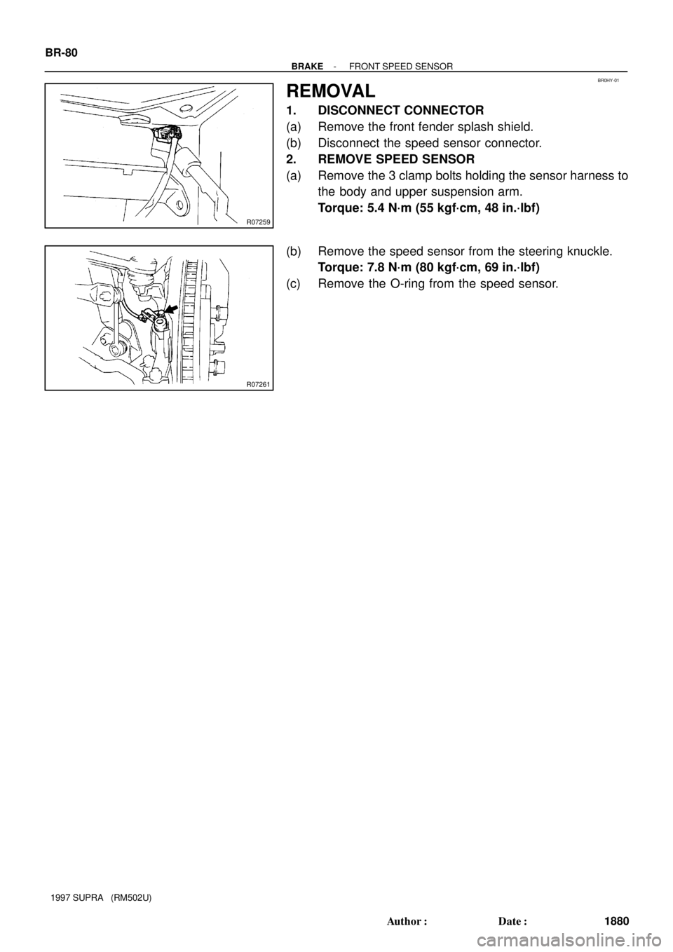
REMOVAL
1. DISCONNECT CONNECTOR
(a) Remove the front fender splash shield.
(b) Disconnect the speed sensor connector.
2. REMOVE SPEED SENSOR
(a) Remove the 3 clamp bolts holding the sensor harness to
the body and upper suspension arm.
Torque: 5.4 N´m (55 kgf´cm, 48 in.´lbf)
(b) Remove the speed sensor from the steering knuckle.
Torque: 7.8 N´m (80 kgf´cm, 69 in.´lbf)
(c) Remove the O-ring from the speed sensor.
Page 367 of 1807
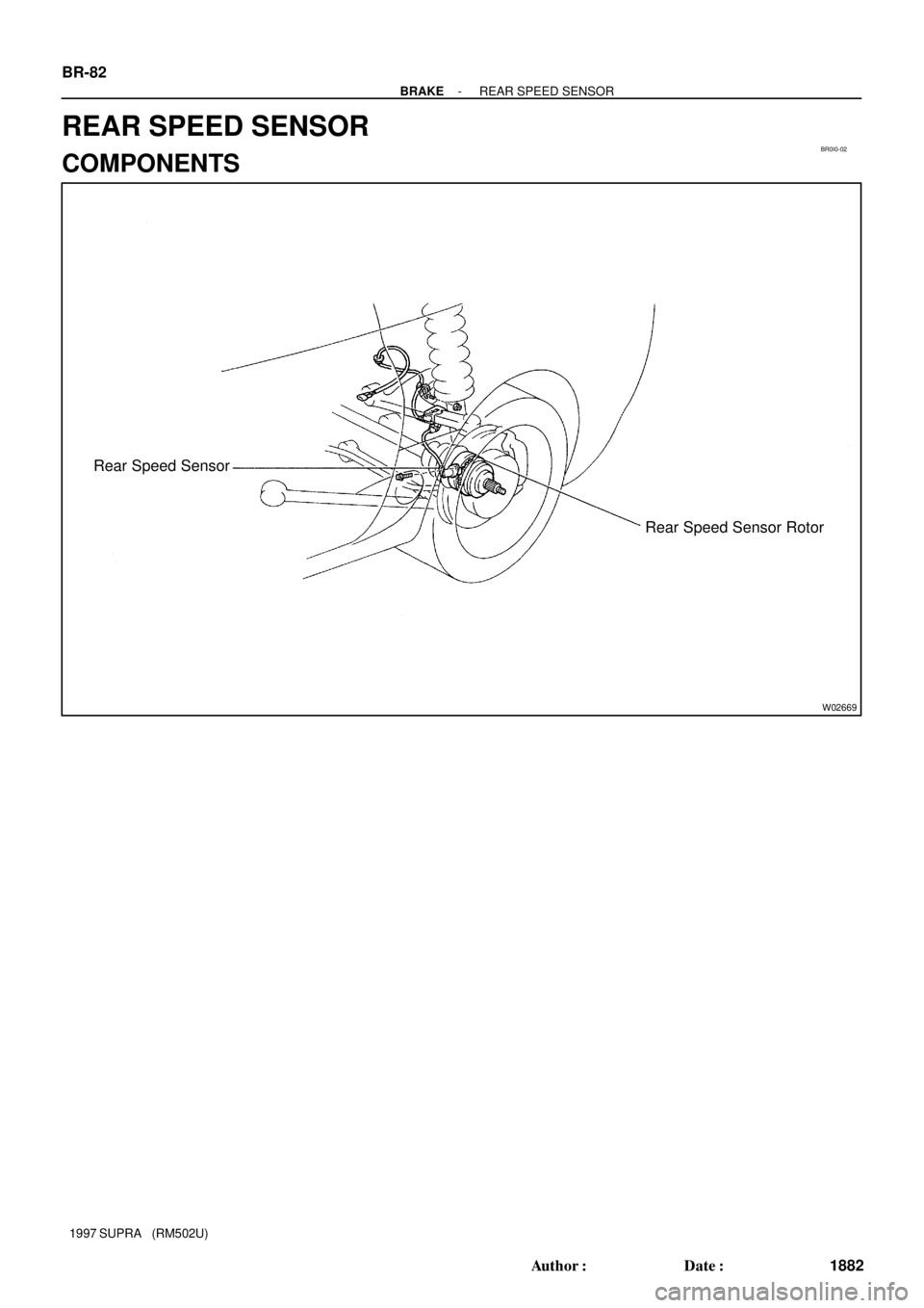
BR0I0-02
W02669
Rear Speed Sensor
Rear Speed Sensor Rotor BR-82
- BRAKEREAR SPEED SENSOR
1882 Author�: Date�:
1997 SUPRA (RM502U)
REAR SPEED SENSOR
COMPONENTS