Page 368 of 1807
BR0I1-01
R07264
R05712
- BRAKEREAR SPEED SENSOR
BR-83
1883 Author�: Date�:
1997 SUPRA (RM502U)
REMOVAL
1. DISCONNECT SPEED SENSOR CONNECTOR
(a) Remove the rear seat cushion and seatback.
(b) Remove the quarter trim panel.
(c) Disconnect the speed sensor connector, and pull out the
sensor wire harness with the grommet.
2. REMOVE SPEED SENSOR
(a) Remove the nut holding the sensor wire harness to the
body.
Torque: 5.4 N´m (55 kgf´cm, 48 in.´lbf)
(b) Remove the clamp from the upper arm.
(c) Remove the speed sensor from the axle carrier.
Torque: 7.8 N´m (80 kgf´cm, 69 in.´lbf)
Page 376 of 1807

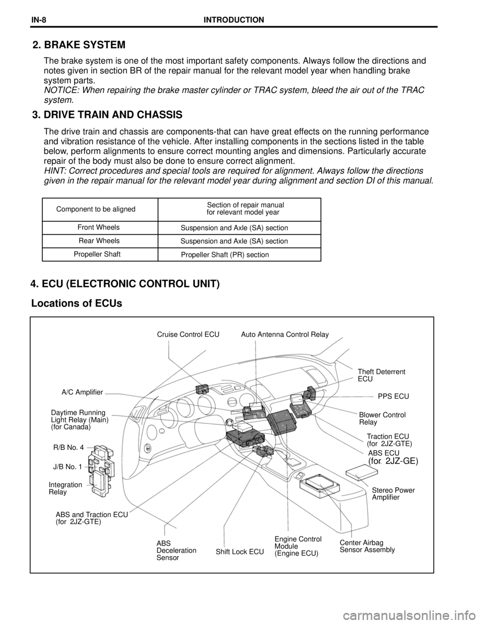
Shift Lock ECUEngine Control
Module
(Engine ECU)Center Airbag
Sensor Assembly ABS
Deceleration
Sensor ABS and Traction ECU
(for 2JZ-GTE)Stereo Power
Amplifier Integration
RelayJ/B No. 1Traction ECU
(for 2JZ-GTE)
R/B No. 4 Daytime Running
Light Relay (Main)
(for Canada)Blower Control
RelayPPS ECU A/C AmplifierTheft Deterrent
ECU Cruise Control ECU Auto Antenna Control Relay
ABS ECU
(for 2JZ-GE)
Component to be alignedSection of repair manual
for relevant model year
Front Wheels
Suspension and Axle (SA) section
Rear Wheels
Suspension and Axle (SA) section
Propeller Shaft
Propeller Shaft (PR) section
3. DRIVE TRAIN AND CHASSIS2. BRAKE SYSTEM
The brake system is one of the most important safety components. Always follow the directions and
notes given in section BR of the repair manual for the relevant model year when handling brake
system parts.
NOTICE: When repairing the brake master cylinder or TRAC system, bleed the air out of the TRAC
system.
The drive train and chassis are components-that can have great effects on the running performance
and vibration resistance of the vehicle. After installing components in the sections listed in the table
below, perform alignments to ensure correct mounting angles and dimensions. Particularly accurate
repair of the body must also be done to ensure correct alignment.
HINT: Correct procedures and special tools are required for alignment. Always follow the directions
given in the repair manual for the relevant model year during alignment and section DI of this manual.
4. ECU (ELECTRONIC CONTROL UNIT)
Locations of ECUs
INTRODUCTIONIN-8
Page 694 of 1807
S05426
From
BatteryR/B
No.2 2
2A
ALT
R/B
No.2
POWER
22W-L
J/B No.1 210
1B 1ESTOP
WStop Light
Switch
21G-W11
IJ1G-W4
A
STPECM
J/B
No.1 1
101H
1C
Light
Failure
Sensor
To Stop LightG-W
7
- DIAGNOSTICSENGINE (2JZ-GTE)
DI-279
507 Author�: Date�:
1997 SUPRA (RM502U)
DTC P1520 Stop Light Switch Signal Malfunction
Only for A/T
CIRCUIT DESCRIPTION
This signal is used to detect when the brakes have been applied. The STP signal voltage is the same as
the voltage supplied to the stop lights.
The STP signal is used mainly to control the fuel cut-off engine speed. (The fuel cut-off engine speed is
reduced slightly when the vehicle is braking.)
DTC No.DTC Detecting ConditionTrouble Area
P1520
The stop light switch does not turn off even once the vehicle is
driven.
(2 trip detection logic)�Short in stop light switch signal circuit
�Stop light switch
�ECM
WIRING DIAGRAM
DI4TK-01
Page 731 of 1807
DI4V4-01
Vehicle Brought to Workshop
Customer Problem Analysis
P. DI-441
Check and Clear DTC (Precheck)
P. DI-442Items inside
are titles of pages in this manual,
with the page number in the bottom portion. See
the pages for detailed explanations.
Problem Symptom ConfirmationSymptom Simulation
P. IN-18
Symptom
does not occur
Symptom
occurs
DTC Check
P. DI-442
Sensor CheckCircuit Inspection
P. DI-453 ~ DI-498
DTC Chart
P. DI-447 Malfunction codeProblem Symptoms Chart
P. DI-452
Check for Fluid Leakage
P. DI-498
Identification of Problem
Normal code
Repair
Confirmation Test
End
1
2
3
4
5
67
89
10
11
Step 2, 5, 8, 9, 11:Diagnostic steps permitting the use of the
TOYOTA hand-held tester or TOYOTA
break-out-box.
DI-440
- DIAGNOSTICSANTI-LOCK BRAKE SYSTEM
668 Author�: Date�:
1997 SUPRA (RM502U)
ANTI-LOCK BRAKE SYSTEM
HOW TO PROCEED WITH TROUBLESHOOTING
Troubleshooting in accordance with the procedure on the following pages.
Page 735 of 1807

F00007
E1
Tc
Ts
lei-23-1-A
DLC1
BR3904
0.13 sec.
0.13 sec.
ON
OFF
BR3893
Malfunction Code (Example Code 72, 76)
7276
ON
OFF
0.5 sec.
0.5 sec.1.5 sec.
0.5 sec.0.5 sec.2.5 sec.
4 sec.
Repeat DI-444
- DIAGNOSTICSANTI-LOCK BRAKE SYSTEM
672 Author�: Date�:
1997 SUPRA (RM502U)
2. SPEED SENSOR SIGNAL AND DECELERATION SEN-
SOR
(a) Check the speed sensor signal and deceleration sensor.
(1) Turn the ignition switch OFF
(2) Using SST, connect terminal Ts and E1 of DLC1.
SST 09843-18020
(3) Start the engine.
(4) Check that the ABS warning light blinks.
HINT:
�If the ABS warning light does not blink, inspect the ABS
warning light circuit (See page DI-488).
�If the ABS warning light is always on, inspect and repair,
deceleration sensor.
(5) Drive the vehicle faster than 45 km/h (28 mph) for
several seconds.
(6) Stop the vehicle.
(7) Using SST, connect terminals Tc an E1 of DLC1.
SST 09843-18020
(8) Read the number of blinks of the ABS warning light.
HINT:
�See the list of DTC shown on the next page.
�If every sensor is normal, a normal code is output (A cycle
of 0.25 sec. ON and 0.25 sec. OFF is repeated).
�If 2 or more malfunctions are indicated at the same time,
the lowest numbered code will be displayed 1st.
(9) After doing the check, disconnect terminals Ts and
E1, Tc and E1 of DLC1, and turn ignition switch OFF.
Page 736 of 1807

FI6997
TOYOTA
Hand-held
tester
DLC2
- DIAGNOSTICSANTI-LOCK BRAKE SYSTEM
DI-445
673 Author�: Date�:
1997 SUPRA (RM502U)
(b) Using TOYOTA hand-held tester, check the DTC.
(1) Do step (1) - (6) on the previous page.
(2) Hook up the TOYOTA hand- held tester to the
DLC2.
(3) Read the DTC by following the prompts on the tes-
ter screen.
Please refer to the TOYOTA hand-held tester oper-
ator 's manual for farther details.
DTC of speed sensor check function:
Code No.DiagnosisTrouble Area
71Low output voltage of right front speed sensor
�Right front speed sensor
�Sensor installation
�Sensor Rotor
72Low output voltage of left front speed sensor
�Left front speed sensor
�Sensor installation
�Sensor Rotor
73Low output voltage of right rear speed sensor
�Right rear speed sensor
�Sensor installation
�Sensor Rotor
74Low output voltage of left rear speed sensor
�Left rear speed sensor
�Sensor installation
�Sensor Rotor
75Abnormal change in output voltage of right front speed sensor�Right front speed sensor rotor
76Abnormal change in output voltage of left front speed sensor�Left front speed sensor rotor
77Abnormal change in output voltage of right rear speed sensor�Right rear speed sensor rotor
78Abnormal change in output voltage of left rear speed sensor�Left rear speed sensor rotor
79*Deceleration sensor is faulty�Deceleration sensor
�Sensor installation
*: SPORT ABS (2JZ-GTE Engine) only
Page 737 of 1807

R10305
GL2
VGS
GGNDGL1
Rear Side
Front Side DI-446
- DIAGNOSTICSANTI-LOCK BRAKE SYSTEM
674 Author�: Date�:
1997 SUPRA (RM502U)
3. DECELERATION SENSOR OPERATION DIAGNOSIS
SYSTEM
CAUTION:
While checking the deceleration sensor operating diagno-
sis system, the Anti-lock Brake System does not work and
brake system works as a conventional brake system.
(a) Deceleration sensor inspection check of deceleration
sensor output:
(1) Connect 3 dry batteries of 1.5 V in series.
(2) Connect VGS terminal to the batteries' positive (+)
terminal, and GGND terminal to the batteries' nega-
tive (-) terminal, apply about 4.5 V between VGS-
GGND terminals.
NOTICE:
Do not apply voltage of 6 V or more to terminals VGS and
GGND.
(3) Check the output of GL1 and GL2 terminals.
SymbolsConditionStandard Value
GL1Horizontalabout 2.3 V
GL1Lean forward0.4 - about 2.3 V
GL1Lean rearwardabout 2.3 V - 4.1 V
GL2Horizontalabout 2.3 V
GL2Lean forwardabout 2.3 V - 4.1 V
GL2Lean rearward0.4 - about 2.3 V
HINT:
�If the senor is tilted too much it may show the wrong value.
�If dropped, the sensor should be replaced with a new one.
�The sensor removed from the vehicle should not be
placed upside down.
Page 738 of 1807

DI4V7-01
- DIAGNOSTICSANTI-LOCK BRAKE SYSTEM
DI-447
675 Author�: Date�:
1997 SUPRA (RM502U)
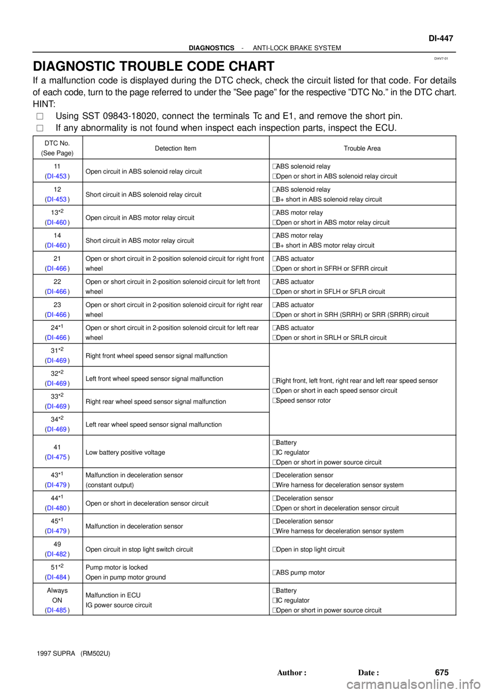
DIAGNOSTIC TROUBLE CODE CHART
If a malfunction code is displayed during the DTC check, check the circuit listed for that code. For details
of each code, turn to the page referred to under the ºSee pageº for the respective ºDTC No.º in the DTC chart.
HINT:
�Using SST 09843-18020, connect the terminals Tc and E1, and remove the short pin.
�If any abnormality is not found when inspect each inspection parts, inspect the ECU.
DTC No.
(See Page)Detection ItemTrouble Area
11
(DI-453)Open circuit in ABS solenoid relay circuit�ABS solenoid relay
�Open or short in ABS solenoid relay circuit
12
(DI-453)Short circuit in ABS solenoid relay circuit�ABS solenoid relay
�B+ short in ABS solenoid relay circuit
13*2
(DI-460)Open circuit in ABS motor relay circuit�ABS motor relay
�Open or short in ABS motor relay circuit
14
(DI-460)Short circuit in ABS motor relay circuit�ABS motor relay
�B+ short in ABS motor relay circuit
21
(DI-466)Open or short circuit in 2-position solenoid circuit for right front
wheel�ABS actuator
�Open or short in SFRH or SFRR circuit
22
(DI-466)Open or short circuit in 2-position solenoid circuit for left front
wheel�ABS actuator
�Open or short in SFLH or SFLR circuit
23
(DI-466)Open or short circuit in 2-position solenoid circuit for right rear
wheel�ABS actuator
�Open or short in SRH (SRRH) or SRR (SRRR) circuit
24*1
(DI-466)
Open or short circuit in 2-position solenoid circuit for left rear
wheel�ABS actuator
�Open or short in SRLH or SRLR circuit
31*2
(DI-469)Right front wheel speed sensor signal malfunction
32*2
(DI-469)Left front wheel speed sensor signal malfunction�Right front, left front, right rear and left rear speed sensor
O htihd iit33*2
(DI-469)Right rear wheel speed sensor signal malfunction
�Open or short in each speed sensor circuit
�Speed sensor rotor
34*2
(DI-469)Left rear wheel speed sensor signal malfunction
41
(DI-475)Low battery positive voltage
�Battery
�IC regulator
�Open or short in power source circuit
43*1
(DI-479)
Malfunction in deceleration sensor
(constant output)�Deceleration sensor
�Wire harness for deceleration sensor system
44*1
(DI-480)Open or short in deceleration sensor circuit�Deceleration sensor
�Open or short in deceleration sensor circuit
45*1
(DI-479)Malfunction in deceleration sensor�Deceleration sensor
�Wire harness for deceleration sensor system
49
(DI-482)Open circuit in stop light switch circuit�Open in stop light circuit
51*2
(DI-484)
Pump motor is locked
Open in pump motor ground�ABS pump motor
Always
ON
(DI-485)Malfunction in ECU
IG power source circuit�Battery
�IC regulator
�Open or short in power source circuit