Page 740 of 1807
DI4V8-01
W02807
2JZ-GE:
2JZ-GTE:
2JZ-GTE:SPORT AVS (2JZ-GTE Engine):
ABS Control
Relay
ABS Solenoid
Relay
ABS Motor RelayABS ActuatorDeceleration Sensor
ABS Warning Light
ABS ECU
DLC1DLC2
Front Speed Sensor RotorRear Speed SensorRear Speed
Sensor Rotor
Front Speed Sensor
- DIAGNOSTICSANTI-LOCK BRAKE SYSTEM
DI-449
677 Author�: Date�:
1997 SUPRA (RM502U)
PARTS LOCATION
Page 743 of 1807

PROBLEM SYMPTOMS TABLE
If a normal code is displayed during the DTC check but the problem still occurs, ch")
DI4VA-01
DI-452
- DIAGNOSTICSANTI-LOCK BRAKE SYSTEM
680 Author�: Date�:
1997 SUPRA (RM502U)
PROBLEM SYMPTOMS TABLE
If a normal code is displayed during the DTC check but the problem still occurs, check the circuits for each
problem symptom in the order given in the table below and proceed to the relevant troubleshooting page.
NOTICE:
When removing the ECU, turn the IG switch OFF.
SymptomsInspection CircuitSee page
ABS does not operate.
Only when 1. - 4. are all normal and the problem is still occurring, replace the ABS
ECU.
1. Check the DTC, reconfirming that the normal code is output.
2. IG power source circuit.
3. Speed sensor circuit.
4. Check the ABS actuator with a checker.
If abnormal, check the hydraulic circuit for leakage (See page DI-498).
DI-442
DI-475
DI-469
BR-66 or XXX
ABS does not operate
efficiently.
Only when 1. - 4. are all normal and the problem is still occurring, replace the ABS
ECU.
1. Check the DTC, reconfirming that the normal code is output.
2. Speed sensor circuit.
3. Stop light switch circuit.
4. Check the ABS actuator with a checker.
If abnormal, check the hydraulic circuit for leakage (See page DI-498).
DI-442
DI-469
DI-482
BR-66 or BR-66
ABS warning light
abnormal.1. ABS warning light circuit.
2. ABS ECU.DI-488
DTC check cannot be done.
Only when 1. and 2. are all normal and the problem is still occurring, replace the
ABS ECU.
1. ABS warning light circuit.
2. Tc terminal circuit.
DI-488
DI-494
Speed sensor signal check
cannot be done.1. Ts terminal circuit.
2. ABS ECU.DI-496XXX
Page 760 of 1807

DTC 31, 32, 33, 34 Speed Senso")
BR3583
BR3582F00010
RotorSpeed Sensor
CoilNSMagnet
To ECU
Low Speed
High Speed
+V
-V
- DIAGNOSTICSANTI-LOCK BRAKE SYSTEM
DI-469
697 Author�: Date�:
1997 SUPRA (RM502U)
DTC 31, 32, 33, 34 Speed Sensor Circuit
CIRCUIT DESCRIPTION
The speed sensor detects the wheel speed and sends the ap-
propriate signals to the ECU. These signals are used to control
the ABS control system. The front and rear rotors each have 48
serrations.
When the rotos rotate, the magnetic field emitted by the perma-
nent magnet in the speed sensor generates an AC voltage.
Since the frequency of this AC voltage changes in direct propor-
tion to the speed of the rotor, the frequency is used by the ECU
to detect the speed of each wheel.
DTC No.DTC Detecting ConditionTrouble Area
31,32,33,34
Detection of any of conditions (1) through (3):
(1) At vehicle speed of 10 km/h (6 mph) or more, pulses are
not input for 15 sec.
(2) Momentary interruption of the vehicle speed sensor signal
occurs at least 7 times in the time between switching the igni-
tion switch ON and switching it OFF.
(3) Abnormal fluctuation of speed sensor signals with the ve-
hicle speed 20 km/h (12 mph) or more.
�Right front, left front, right rear and left rear speed sensor
�Open or short in each speed sensor circuit
�Sensor rotor
HINT:
DTC No.31 is for the right front speed sensor.
DTC No.32 is for the left front speed sensor.
DTC No.33 is for the right rear speed sensor.
DTC No.34 is for the left rear speed sensor.
Fail safe function:
If trouble occurs in the speed sensor circuit, the ECU cuts off current to the ABS solenoid relay and prohibits
ABS control.
DI4VE-01
Page 761 of 1807
W02989
IB5
IB5
IB2
IB2
IC2
IC2A19 A21
8 Right Front
Speed Sensor2
1L R
EA3
14 9
198
2 20
110
723
322
109FR+
FR-ABS ECU
5V
FL+
FL-
RR+
RR-
RL+
RL- R
L
W
B
V
LG 1
2
4
5
L
P
3 W
B
V
LG 2
2
2 1
1
1 Left Front
Speed Sensor
Right Rear
Speed Sensor
Left Rear
Speed Sensor
*1
3
*2
A19A21
A19
A21
A19
A21
A18
A20
A18
A20
A18
A20
A18
A20 DI-470
- DIAGNOSTICSANTI-LOCK BRAKE SYSTEM
698 Author�: Date�:
1997 SUPRA (RM502U)
WIRING DIAGRAM
*1: NORMAL ABS (2JZ-GE Engine)
*2: SPORT ABS (2JZ-GTE Engine)
Page 762 of 1807
F02629F03325F03327
LOCK
21
- DIAGNOSTICSANTI-LOCK BRAKE SYSTEM
DI-471
699 Author�: Date�:
1997 SUPRA (RM502U)
INSPECTION PROCEDURE
1 Check speed sensor.
Front
PREPARATION:
(a) Remove front fender splash shield.
(b) Disconnect speed sensor connector.
CHECK:
Measure resistance between terminals 1 and 2 of speed sensor
connector.
OK:
Resistance: 0.6 - 2.5 kW
CHECK:
Measure resistance between terminals 1 and 2 of speed sensor
connector and body ground.
OK:
Resistance: 1 MW or higher
CHECK:
Check the sensor connector.
OK:
(1) There is not play on the connector connecting
part.
(2) Connectors are connected each other securely.
Page 763 of 1807
F02629F03326F03328
LOCK
1
2
DI-472
- DIAGNOSTICSANTI-LOCK BRAKE SYSTEM
700 Author�: Date�:
1997 SUPRA (RM502U)
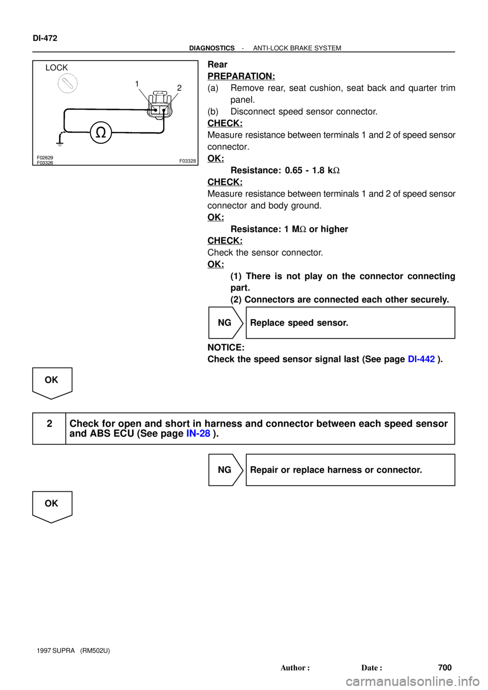
Rear
PREPARATION:
(a) Remove rear, seat cushion, seat back and quarter trim
panel.
(b) Disconnect speed sensor connector.
CHECK:
Measure resistance between terminals 1 and 2 of speed sensor
connector.
OK:
Resistance: 0.65 - 1.8 kW
CHECK:
Measure resistance between terminals 1 and 2 of speed sensor
connector and body ground.
OK:
Resistance: 1 MW or higher
CHECK:
Check the sensor connector.
OK:
(1) There is not play on the connector connecting
part.
(2) Connectors are connected each other securely.
NG Replace speed sensor.
NOTICE:
Check the speed sensor signal last (See page DI-442).
OK
2 Check for open and short in harness and connector between each speed sensor
and ABS ECU (See page IN-28).
NG Repair or replace harness or connector.
OK
Page 764 of 1807
F03329
R00948
- DIAGNOSTICSANTI-LOCK BRAKE SYSTEM
DI-473
701 Author�: Date�:
1997 SUPRA (RM502U)
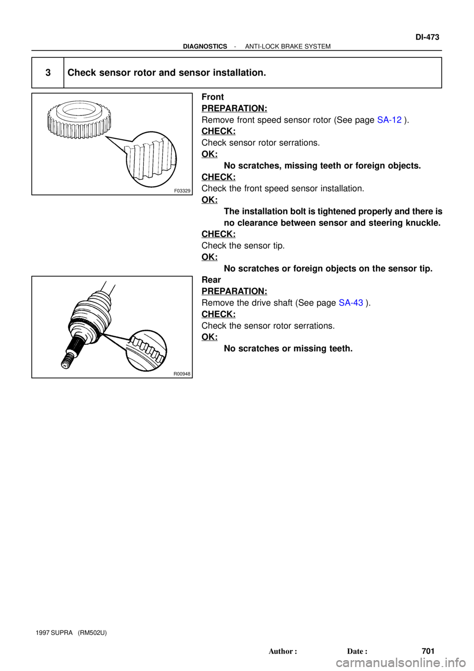
3 Check sensor rotor and sensor installation.
Front
PREPARATION:
Remove front speed sensor rotor (See page SA-12).
CHECK:
Check sensor rotor serrations.
OK:
No scratches, missing teeth or foreign objects.
CHECK:
Check the front speed sensor installation.
OK:
The installation bolt is tightened properly and there is
no clearance between sensor and steering knuckle.
CHECK:
Check the sensor tip.
OK:
No scratches or foreign objects on the sensor tip.
Rear
PREPARATION:
Remove the drive shaft (See page SA-43).
CHECK:
Check the sensor rotor serrations.
OK:
No scratches or missing teeth.
Page 765 of 1807
BR3795OK
NG
DI-474
- DIAGNOSTICSANTI-LOCK BRAKE SYSTEM
702 Author�: Date�:
1997 SUPRA (RM502U)
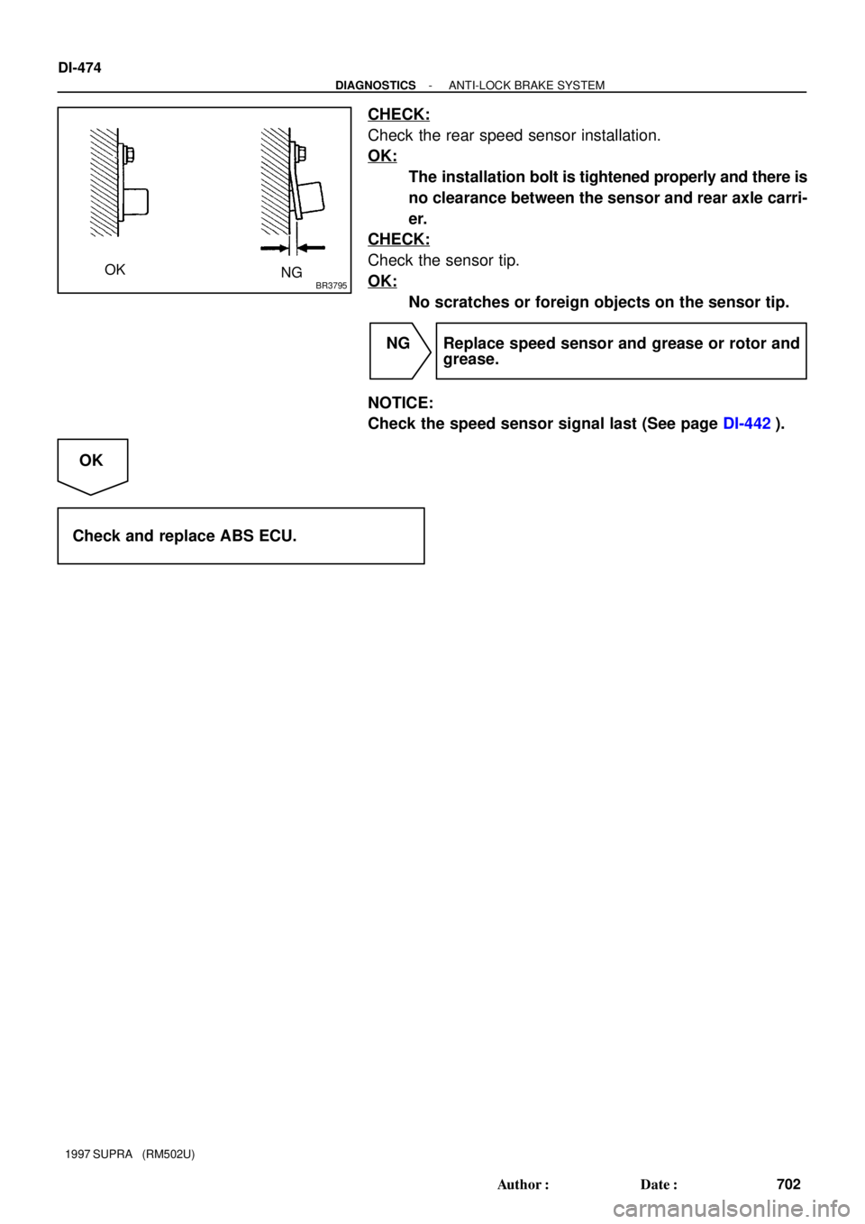
CHECK:
Check the rear speed sensor installation.
OK:
The installation bolt is tightened properly and there is
no clearance between the sensor and rear axle carri-
er.
CHECK:
Check the sensor tip.
OK:
No scratches or foreign objects on the sensor tip.
NG Replace speed sensor and grease or rotor and
grease.
NOTICE:
Check the speed sensor signal last (See page DI-442).
OK
Check and replace ABS ECU.
:
ABS Control
Relay
ABS Solenoid
Relay
ABS Motor RelayABS ActuatorDeceleration Sensor
ABS Warning Light
ABS ECU
DLC1DLC2
Front Speed")