Page 794 of 1807

DIAGNOSTIC TROUBLE CODE CHART
HINT:
Using SST 09843-18020, connect the terminals Tc and E
1.
If a m")
DI4VS-01
- DIAGNOSTICSABS & TRACTION CONTROL SYSTEM
DI-503
731 Author�: Date�:
1997 SUPRA (RM502U)
DIAGNOSTIC TROUBLE CODE CHART
HINT:
Using SST 09843-18020, connect the terminals Tc and E
1.
If a malfunction code is displayed during the DTC check, check the circuit listed for that code. For details
of each code, turn to the page referred to under the ºSee pageº for the respective ºDTC No.º in the DTC chart.
DTC No.
(See Page)Detection ItemTrouble Area
11
(DI-509)Throttle control relay circuit open
�Throttle control relay
�TRAC fuse
�Wire harness and connector (throttle control relay circuit)
�Throttle control ECU
12
(DI-509)Throttle control relay circuit short
�Throttle control relay
�Wire harness and connector (throttle control relay circuit)
�Throttle control ECU
21
(DI-513)Sub-throttle valve motor circuit open or short
�Sub-throttle valve motor
�Wire harness and connector (sub-throttle valve motor and
E01 circuit)
�Throttle control ECU
22
(DI-513)Sub-throttle valve motor malfunction
�Sub-throttle valve motor
�Sub-throttle valve
�Sub-throttle position sensor
�Wire harness and connector (E1 circuit)
�Throttle control ECU
23
(DI-516)Throttle body malfunction
�Sub-throttle valve
�Sub-throttle position sensor
�Throttle control ECU
24
(DI-519)Sub-throttle position sensor leakage/sub-throttle valve stuck
�Sub-throttle valve
�Sub-throttle position sensor
�Wire harness and connector (E1 circuit)
�Throttle control ECU
31
(DI-522)Throttle position sensor signal malfunction
�Throttle position sensor
�Wire harness and connector (throttle position senor and E1
circuit)
�Throttle control ECU
32
(DI-526)Sub-throttle position sensor signal malfunction
�Sub-throttle position sensor
�Sub-throttle valve motor
�Sub-throttle valve
�Wire harness and connector (sub-throttle position senor and
E1 circuit)
�Throttle control ECU
41
(DI-530)Engine revolution signal open or short
�Wire harness and connector (NE circuit)
�ECM
�Throttle control ECU
42
(DI-532)ECM malfunction
�Wire harness and connector (EFIF circuit)
�ECM
�Throttle control ECU
43
(DI-534)ECM communication circuit malfunction
�Wire harness and connector (EFI+ and EFI- circuit)
�ECM
�Throttle control ECU
51
(DI-535)Power source voltage down
(sub-throttle valve in a bad condition)�Wire harness and connector (+B and E01 circuit)
�Throttle control ECU
Page 940 of 1807
I02561
LOCK
+B2 (+)
- DIAGNOSTICSTHEFT DETERRENT SYSTEM
DI-649
877 Author�: Date�:
1997 SUPRA (RM502U)
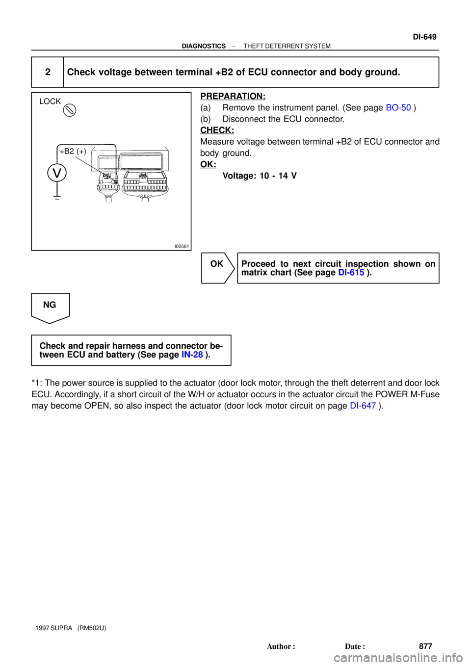
2 Check voltage between terminal +B2 of ECU connector and body ground.
PREPARATION:
(a) Remove the instrument panel. (See page BO-50)
(b) Disconnect the ECU connector.
CHECK:
Measure voltage between terminal +B2 of ECU connector and
body ground.
OK:
Voltage: 10 - 14 V
OK Proceed to next circuit inspection shown on
matrix chart (See page DI-615).
NG
Check and repair harness and connector be-
tween ECU and battery (See page IN-28).
*1: The power source is supplied to the actuator (door lock motor, through the theft deterrent and door lock
ECU. Accordingly, if a short circuit of the W/H or actuator occurs in the actuator circuit the POWER M-Fuse
may become OPEN, so also inspect the actuator (door lock motor circuit on page DI-647).
Page 1007 of 1807
8
B HOW TO USE THIS MANUAL
The Current Flow Chartº section, describes which parts each power source (fuses, fusible links, and circuit
breakers) transmits current to. In the Power Source circuit diagram, the conditions when battery power is
supplied to each system are explained. Since all System Circuit diagrams start from the power source, the power
source system must be fully understood.
* The system shown here is an EXAMPLE ONLY. It is different to the actual circuit shown in the SYSTEM CIRCUITS SECTION.
H POWER SOURCE (CURRENT FLOW CHART)
The chart below shows the route by which current flows from the battery to each electrical source (Fusible Link, Circuit Breaker, Fuse,
etc.) and other parts.
The next page and following pages shown the parts to which each electrical source outputs current.
POWER SOURCE
Page 1050 of 1807
44
H POWER SOURCE (Current Flow Chart)
The chart below shows the route by which current flows from the battery to each electrical source
(Fusible Link, Circuit Breaker, Fuse, etc.) and other parts.
The next page and following pages show the parts to which each electrical source outputs current.
[LOCATION]1: J/B No. 1 (See page 20) 2: R/B No.2 (See page 22)
 transmits current to. In the Power Source circuit")

The chart below shows the route by which current flows from the battery to each electrical source
(Fusible Link, Circuit Breaker, Fuse, etc.) and other parts.
T")