Page 165 of 1807

DEFOGGER SYSTEM
SymptomSuspect AreaSee page
All defogger systems do not operate.
1. GAUGE Fuse (J/B No.1)
2. DEF")
- BODY ELECTRICALBODY ELECTRICAL SYSTEM
BE-9
1987 Author�: Date�:
1997 SUPRA (RM502U)
DEFOGGER SYSTEM
SymptomSuspect AreaSee page
All defogger systems do not operate.
1. GAUGE Fuse (J/B No.1)
2. DEFOG Fuse (J/B No.1)
3. Defogger Relay (R/B No.4)
4. Defogger Switch
5. A/C Amplifier
6 Wire Harness
BE-56
BE-56
DI-71 1
Rear window defogger does not operate.1. Defogger Wires
2. Wire HarnessBE-56
Mirror defogger does not operate.
1. MIR-HTR Fuse (J/B No.1)
2. Mirror Defogger
3. Wire Harness
BE-56
POWER WINDOW CONTROL SYSTEM
SymptomSuspect AreaSee page
Power window does not operate.
(Power door lock does not operate.)
1. POWER Fuse (R/B No.2)
2. DOOR Fuse (J/B No.1)
3. Ignition Switch
4. Power Window Master Switch
5. Wire Harness
BE-13
BE-60
Power Window does not operate.
(Power door lock is normal.)
1. GAUGE Fuse (J/B No.1)
2. Power Main Relay (J/B No.1)
3. Ignition Switch
4. Power Window Master Switch
5. Wire Harness
BE-60
BE-13
BE-60
ºOne Touch Power Window Systemº does not operate.1. Power Window Master SwitchBE-60
Only one window glass does not move.
1. Power Window Master Switch
2. Power Window Switch
3. Power Window Motor
4. Wire HarnessBE-60
BE-60
BE-60
ºWindow Lock Systemº does not operate.1. Power Window Master SwitchBE-60
Illumination does not light up.1. Power Window Master SwitchBE-60
POWER SEAT CONTROL SYSTEM
SymptomSuspect AreaSee page
Power seat does not operate.
1. POWER Fuse (R/B No.2)
2. DOOR Fuse (J/B No.1)
3. Power Seat Switch
4. Wire Harness
BE-65
ºSlide operationº does not operate.
1. Power Seat Switch
2. Sliding Motor
3. Wire HarnessBE-65
BE-65
ºReclining operationº does not operate.
1. Power Seat Switch
2. Reclining Motor
3. Wire HarnessBE-65
BE-65
Page 166 of 1807
BE-10
- BODY ELECTRICALBODY ELECTRICAL SYSTEM
1988 Author�: Date�:
1997 SUPRA (RM502U)
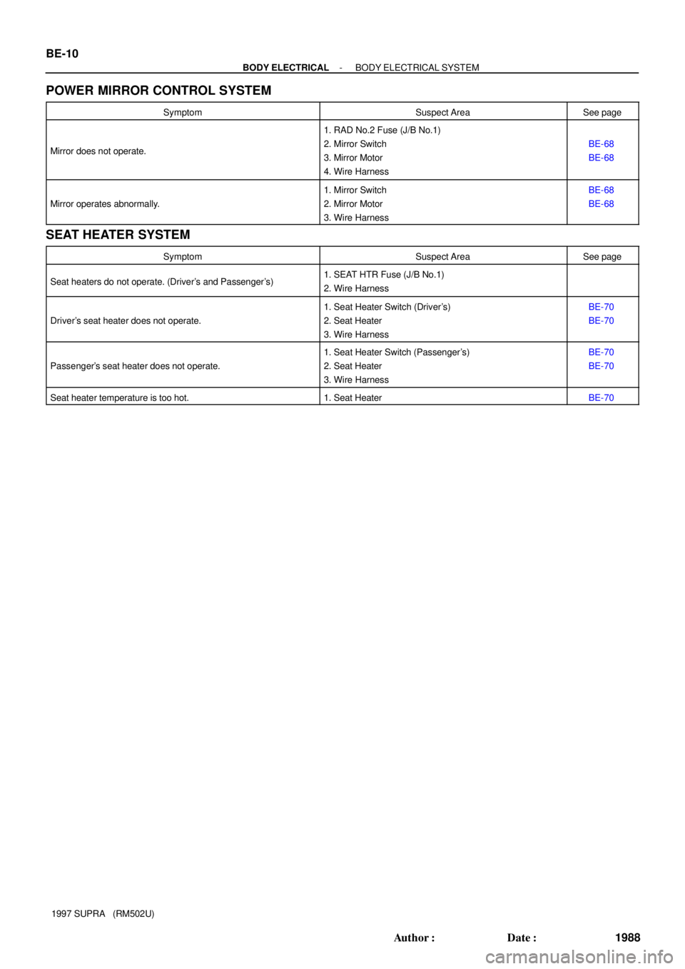
POWER MIRROR CONTROL SYSTEM
SymptomSuspect AreaSee page
Mirror does not operate.
1. RAD No.2 Fuse (J/B No.1)
2. Mirror Switch
3. Mirror Motor
4. Wire Harness
BE-68
BE-68
Mirror operates abnormally.
1. Mirror Switch
2. Mirror Motor
3. Wire HarnessBE-68
BE-68
SEAT HEATER SYSTEM
SymptomSuspect AreaSee page
Seat heaters do not operate. (Driver's and Passenger's)1. SEAT HTR Fuse (J/B No.1)
2. Wire Harness
Driver's seat heater does not operate.
1. Seat Heater Switch (Driver's)
2. Seat Heater
3. Wire HarnessBE-70
BE-70
Passenger's seat heater does not operate.
1. Seat Heater Switch (Passenger's)
2. Seat Heater
3. Wire HarnessBE-70
BE-70
Seat heater temperature is too hot.1. Seat HeaterBE-70
Page 211 of 1807
Z18235
Outer Rear View Mirror LH
Mirror DefoggerA/C Control Panel Assembly
Defogger Switch
Outer Rear View Mirror RH
Mirror Defogger
Rear Window Defogger Defogger Relay R/B No.4
MIR-HTR Fuse DEFOG Fuse GAUGE Fuse J/B No.1
�
�
� �
� �
�
BE0EC-01
- BODY ELECTRICALDEFOGGER SYSTEM
BE-55
2033 Author�: Date�:
1997 SUPRA (RM502U)
DEFOGGER SYSTEM
LOCATION
Page 214 of 1807

(d) Using a fine tip brush, apply a small amount to the wire.
(e) After a few m")
BE0151
N08878
Z13354
Wire Harness Side BE-58
- BODY ELECTRICALDEFOGGER SYSTEM
2036 Author�: Date�:
1997 SUPRA (RM502U)
(d) Using a fine tip brush, apply a small amount to the wire.
(e) After a few minutes, remove the masking tape.
(f) Do not repair the defogger wire for at least 24 hours.
6. INSPECT MIRROR DEFOGGER OPERATION
(a) Connect the positive (+) lead from the battery to terminal
2 and the negative (-) lead to terminal 1.
(b) Check that the mirror becomes warm.
HINT:
It will take a short time for the mirror to become warm.
If the mirror does not become warm, replace the mirror assem-
bly.
7. INSPECT MIRROR DEFOGGER CIRCUIT
Disconnect the connector from the outside mirror and inspect
the connector on the wire harness side, as shown.
Tester connectionConditionSpecified condition
1 - GroundConstantContinuity
2 - GroundIgnition switch ON (Defogger switch OFF)No voltage
2 - GroundIgnition switch ON (Defogger switch ON)Battery positive voltage
If the circuit is not as specified, inspect the circuits connected
to other parts.
Page 223 of 1807
Z18238
Outer Rear View Mirror LHOuter Rear View Mirror RH
Mirror Defogger Mirror Motor
Mirror Switch
PAD No.2 Fuse�
J/B No.1�
�
BE0EI-01
- BODY ELECTRICALPOWER MIRROR CONTROL SYSTEM
BE-67
2045 Author�: Date�:
1997 SUPRA (RM502U)
POWER MIRROR CONTROL SYSTEM
LOCATION
Page 224 of 1807

INSPECTION
1. INSPECT MIRROR SWITCH CONTINUITY
Left Side
Switch positionTest")
BE0EJ-01
Z14748
N08882
N08883
BE-68
- BODY ELECTRICALPOWER MIRROR CONTROL SYSTEM
2046 Author�: Date�:
1997 SUPRA (RM502U)
INSPECTION
1. INSPECT MIRROR SWITCH CONTINUITY
Left Side
Switch positionTester connectionSpecified condition
OFF-No continuity
UP2 - 5, 6 - 8Continuity
DOWN2 - 6, 5 - 8Continuity
LEFT1 - 8, 2 - 5Continuity
RIGHT1 - 2, 5 - 8Continuity
Right Side
Switch positionTester connectionSpecified condition
OFF-No continuity
UP2 - 5, 3 - 8Continuity
DOWN2 - 3, 5 - 8Continuity
LEFT2 - 5, 7 - 8Continuity
RIGHT2 - 7, 5 - 8Continuity
If continuity is not as specified, replace the switch.
2. INSPECT MIRROR MOTOR OPERATION
(a) Connect the positive (+) lead from the battery to terminal
3 and negative (-) lead to terminal 4, and check that the
mirror turns upward.
(b) Reverse the polarity, and check that the mirror turns to
downward.
(c) Connect the positive (+) lead from the battery to terminal
5 and negative (-) lead to terminal 4, and check that the
mirror turns to left side.
(d) Reverse the polarity, and check that the mirror turns to
right side.
If operation is not as specified, replace the mirror.
Page 265 of 1807
BO0QC-01
N19534
Outside Handle
Door Lock CylinderDoor Glass
Belt Moulding
Outer Rear View Mirror
Door Hinge
Door Check Door Window Upper Stop
Door Lock
Door Hinge
Weatherstrip
Glass Guide
Service Hole Cover Inside Panel
Frame
Window Regulator
Armrest Bracket
Setting Nut
Window Guide
Lower PlateInside Handle
Plate
Trim BoardInside Handle
Speaker
Power Window Switch
(Passenger's) Inside Handle Bezel
Power Window Master Switch
� Precoated part
7.4 (76, 67 in.´lbf)
11 (115, 8.3)
52 (530, 38)
25 (260, 19)
5.0 (51, 44 in.´lbf)
5.4 (55, 48 in.´lbf)7.4 (76, 67 in.´lbf)
N´m (kgf´cm, ft´lbf): Specified torque
- BODYFRONT DOOR
BO-7
2087 Author�: Date�:
1997 SUPRA (RM502U)
FRONT DOOR
COMPONENTS
Page 267 of 1807

N19388
- BODYFRONT DOOR
BO-9
2089 Author�: Date�:
1997 SUPRA (RM502U)
6. REMOVE WINDOW REGULATOR
(a) Disconnect the connector.
(b) Remove the bolt, 2 nuts and")
N19389
N19532
0 - 1.0 mm
(0 - 0.04 mm)
N19388
- BODYFRONT DOOR
BO-9
2089 Author�: Date�:
1997 SUPRA (RM502U)
6. REMOVE WINDOW REGULATOR
(a) Disconnect the connector.
(b) Remove the bolt, 2 nuts and window regulator.
Torque: 7.4 N´m (76 kgf´cm, 67 in.´lbf)
HINT:
At the time of reassembly, please refer to the following item.
Apply MP grease to the glass guide and rollers of the window
regulator.
7. REMOVE DOOR LOCK
(a) Disconnect the connector and clamp.
(b) Disconnect the link from the outside handle.
HINT:
At the time of reassembly, please refer to the following item.
After connecting the link, check that the clearance is within the
specification as shown in the illustration.
(c) Remove the 3 screws.
Torque: 5.0 N´m (51 kgf´cm, 44 in.´lbf)
HINT:
At the time of reassembly, please refer to the following item.
Apply adhesive to the 3 screws.
Part No.08833-00070, THREE BOND 1324 or equiva-
lent.
(d) Remove the door lock through the service hole.
HINT:
At the time of reassembly, please refer to the following item.
Apply MP grease to the sliding and rotating parts of the door
lock.
8. REMOVE THESE PARTS:
(a) Outside handle
(b) Door lock cylinder
(c) Outer rear view mirror