Page 287 of 1807
BO0QZ-01
N19396
Inner Rear View Mirror
� Spacer
� Spacer
�Stopper
HolderSun Visor
� Outside Moulding
Windshield
� Dam
Wiper Arm And Blade
Front Pillar Garnish RH
Assist GripFront Pillar Garnish LH
Front Fender to Cowl Side Seal
Cowl Top Ventilator Louver
Hood to Cowl Top Seal Front Fender to
Cowl Side Seal
� Non-reusable part
- BODYWINDSHIELD
BO-31
2111 Author�: Date�:
1997 SUPRA (RM502U)
WINDSHIELD
COMPONENTS
Page 288 of 1807

BO0R0-01
N08453
BO5232
BO1689
BO-32
- BODYWINDSHIELD
2112 Author�: Date�:
1997 SUPRA (RM502U)
REMOVAL
1. REMOVE THESE PARTS:
(a) Inner rear view mirror
(b) Sun visors and holders
(c) Assist grip (See page BO-61)
HINT:
Tape a screwdriver tip before use.
(d) Front pillar garnishes (See page BO-61)
(e) Wiper arms and blades
(f) Cowl top ventilator louver
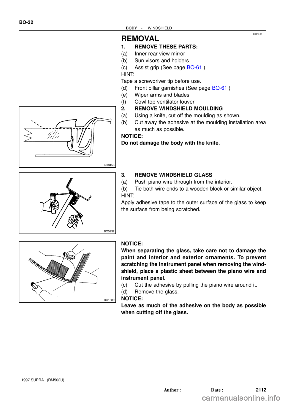
2. REMOVE WINDSHIELD MOULDING
(a) Using a knife, cut off the moulding as shown.
(b) Cut away the adhesive at the moulding installation area
as much as possible.
NOTICE:
Do not damage the body with the knife.
3. REMOVE WINDSHIELD GLASS
(a) Push piano wire through from the interior.
(b) Tie both wire ends to a wooden block or similar object.
HINT:
Apply adhesive tape to the outer surface of the glass to keep
the surface from being scratched.
NOTICE:
When separating the glass, take care not to damage the
paint and interior and exterior ornaments. To prevent
scratching the instrument panel when removing the wind-
shield, place a plastic sheet between the piano wire and
instrument panel.
(c) Cut the adhesive by pulling the piano wire around it.
(d) Remove the glass.
NOTICE:
Leave as much of the adhesive on the body as possible
when cutting off the glass.
Page 292 of 1807
N08452
BO-36
- BODYWINDSHIELD
2116 Author�: Date�:
1997 SUPRA (RM502U)
12. INSTALL WINDSHIELD MOULDING
Place the moulding onto the body and tap it by hand.
13. INSPECT FOR LEAKS AND REPAIR
(a) Do a leak test after the hardening time has elapsed.
(b) Seal any leak with auto glass sealer.
Part No. 08833-00030 or equivalent
14. INSTALL THESE PARTS:
(a) Cowl top ventilator louver
(b) Wiper arms and blades
Torque: 22 N´m (225 kgf´cm, 16 ft´lbf)
(c) Front pillar garnishes
(d) Assist grip
(e) Sun visors and holders
(f) Inner rear view mirror
Page 374 of 1807

Steering Wheel Pad
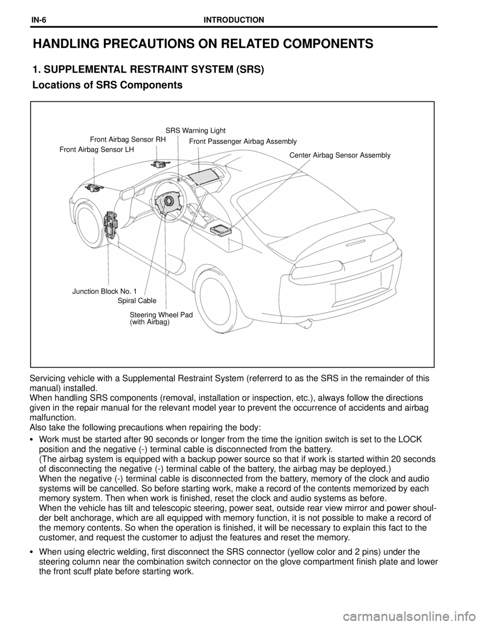
(with Airbag) Junction Block No. 1Center Airbag Sensor Assembly Front Airbag Sensor LHFront Passenger Airbag Assembly Front Airbag Sensor RHSRS Warning Light
Spiral Cable
Locations of SRS Components
HANDLING PRECAUTIONS ON RELATED COMPONENTS
1. SUPPLEMENTAL RESTRAINT SYSTEM (SRS)
Servicing vehicle with a Supplemental Restraint System (referrerd to as the SRS in the remainder of this
manual) installed.
When handling SRS components (removal, installation or inspection, etc.), always follow the directions
given in the repair manual for the relevant model year to prevent the occurrence of accidents and airbag
malfunction.
Also take the following precautions when repairing the body:
�Work must be started after 90 seconds or longer from the time the ignition switch is set to the LOCK
position and the negative (-) terminal cable is disconnected from the battery.
(The airbag system is equipped with a backup power source so that if work is started within 20 seconds
of disconnecting the negative (-) terminal cable of the battery, the airbag may be deployed.)
When the negative (-) terminal cable is disconnected from the battery, memory of the clock and audio
systems will be cancelled. So before starting work, make a record of the contents memorized by each
memory system. Then when work is finished, reset the clock and audio systems as before.
When the vehicle has tilt and telescopic steering, power seat, outside rear view mirror and power shoul-
der belt anchorage, which are all equipped with memory function, it is not possible to make a record of
the memory contents. So when the operation is finished, it will be necessary to explain this fact to the
customer, and request the customer to adjust the features and reset the memory.
�When using electric welding, first disconnect the SRS connector (yellow color and 2 pins) under the
steering column near the combination switch connector on the glove compartment finish plate and lower
the front scuff plate before starting work.
INTRODUCTIONIN-6
Page 377 of 1807

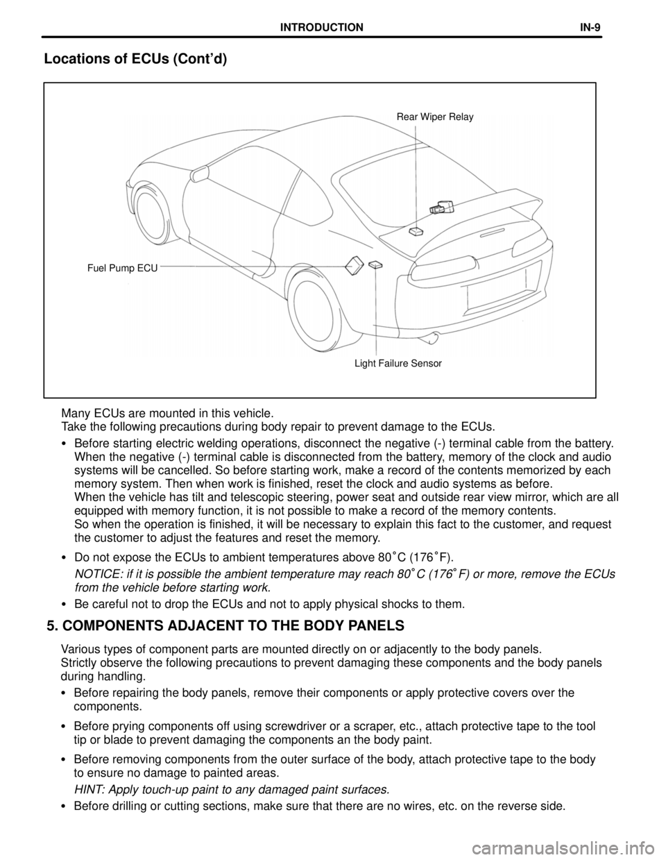
Light Failure Sensor Fuel Pump ECURear Wiper Relay
5. COMPONENTS ADJACENT TO THE BODY PANELS Locations of ECUs (Cont'd)
Many ECUs are mounted in this vehicle.
Take the following precautions during body repair to prevent damage to the ECUs.
�Before starting electric welding operations, disconnect the negative (-) terminal cable from the battery.
When the negative (-) terminal cable is disconnected from the battery, memory of the clock and audio
systems will be cancelled. So before starting work, make a record of the contents memorized by each
memory system. Then when work is finished, reset the clock and audio systems as before.
When the vehicle has tilt and telescopic steering, power seat and outside rear view mirror, which are all
equipped with memory function, it is not possible to make a record of the memory contents.
So when the operation is finished, it will be necessary to explain this fact to the customer, and request
the customer to adjust the features and reset the memory.
�Do not expose the ECUs to ambient temperatures above 80°C (176°F).
NOTICE: if it is possible the ambient temperature may reach 80°C (176°F) or more, remove the ECUs
from the vehicle before starting work.
�Be careful not to drop the ECUs and not to apply physical shocks to them.
Various types of component parts are mounted directly on or adjacently to the body panels.
Strictly observe the following precautions to prevent damaging these components and the body panels
during handling.
�Before repairing the body panels, remove their components or apply protective covers over the
components.
�Before prying components off using screwdriver or a scraper, etc., attach protective tape to the tool
tip or blade to prevent damaging the components an the body paint.
�Before removing components from the outer surface of the body, attach protective tape to the body
to ensure no damage to painted areas.
HINT: Apply touch-up paint to any damaged paint surfaces.
�Before drilling or cutting sections, make sure that there are no wires, etc. on the reverse side.
INTRODUCTIONIN-9
Page 444 of 1807
LOCATION OF PLASTIC BODY PARTS
Outer Rear View Mirror (ABS)
Front Door Outside Handle (PC)
Instrument Panel Safety Pad (PVC/PUR)
Rear Spoiler (SMC/UP)
Cowl Top Ventilator Louver (PP)
Hood Bulge (BMC)
Headlamp (PC/PP)
Quarter Lower
Moulding (PP)
Quarter Panel Air Inlet
Garnish (PUR)
Body Rocker Panel Moulding (PP) Front Bumper Extension
Mounting Bracket (PP)
Front Fender Moulding (PP)
Side Turn Signal Lamp (SAN/ABS)
Front Spoiler Cover (PUR)
Front Side Marker Lamp (PMMA/ABS)
Front Turn Signal Lamp (PMMA/PP)
Front Bumper Cover (PUR)
Front Active Spoiler (PUR)
HINT:
w Resin material differs with model.
/ Made up of 2 or more kinds of materials.
PLASTIC BODY PARTSPP-4
Page 1029 of 1807

29
G
Position of Parts in Instrument Panel
O 5 O/D Main SW and A/T Indicator Illumination
P 4 PPS ECU
P 5 Parking Brake SW
R 4 Radio and Player (w/o Stereo Power Amplifier)
R 5 Radio and Player (w/o Stereo Power Amplifier)
R 6 Radio and Player (w/ Stereo Power Amplifier)
R 7 Remote Control Mirror SW
R 8 Rheostat
S 6 Seat Heater SW
S 7 Shift Lock ECU
S 8 Stereo Power Amplifier
S 9 Stereo Power Amplifier
S10 Stereo Power Amplifier
S11 Stop Light SW
S16 Sub Heated Oxygen Sensor (Bank 1 Sensor 2)
T 5 Telltale Light LH
T 6 Telltale Light RH
T 7 Theft Deterrent and Door Lock Control ECU
T 8 Traction Control SW
T13 Theft Deterrent and Door Lock Control ECU
T15 Throttle ECU
T16 Throttle ECU
U 1 Unlock Warning SW E 8 Electronically Controlled Transmission Pattern
Select SW
E 9 Engine Control Module
E10 Engine Control Module
E11 Engine Coolant Temp. Sensor (A/C System)
F10 Front Tweeter (Speaker) LH
F11 Front Tweeter (Speaker) RH
G 3 Glove Box Light
G 4 Glove Box Light SW
H10 Hazard SW
H11 Heated Oxygen Sensor (Bank 1 Sensor 2)
H12 Heater Control SW
H13 Heater Control SW
I18 Ignition Key Cylinder Light
I19 Ignition SW
I20 Integration Relay
J 1 Junction Connector
J 2 Junction Connector
K 4 Kick Down SW
N 2 Noise Filter
Page 1030 of 1807

30
G ELECTRICAL WIRING ROUTING
Position of Parts in Body
N 3 Noise Filter
P 6 Personal Light
P 7 Power Window Control SW RH
P 8 Power Window Master SW and Door Lock Control
SW LH
P 9 Power Window Motor LH
P10 Power Window Motor RH
R 9 Rear Combination Light LH
R10 Rear Combination Light RH
R11 Rear Side Marker Light LH
R12 Rear Side Marker Light RH
R13 Rear Speaker LH
R14 Rear Speaker RH
R15 Rear Wiper Motor and Relay
R16 Remote Control Mirror and Mirror Heater LH
R17 Remote Control Mirror and Mirror Heater RH
R18 Rear Window Defogger (+)
R19 Rear Window Defogger (-)
T11 Tension Reducer Solenoid LH
T12 Tension Reducer Solenoid RH
W 2 Woofer (Speaker) A31 ABS Speed Sensor Rear LH
A32 ABS Speed Sensor Rear RH
A33 Auto Antenna Motor
D10 Door Courtesy SW LH
D11 Door Courtesy SW RH
D12 Door Key Lock and Unlock SW LH
D13 Door Key Lock and Unlock SW RH
D14 Door Lock Control SW RH
D15 Door Lock Motor and Door Unlock Detection SW LH
D16 Door Lock Motor and Door Unlock Detection SW RH
F12 Front Door Speaker LH
F13 Front Door Speaker RH
F14 Fuel Pump and Sender
F15 Fuel Pump ECU
H14 High Mounted Stop Light
L 1 License Plate Light
L 2 Light Failure Sensor
L 3 Luggage Compartment Key Unlock SW
L 4 Luggage Compartment Light
L 5 Luggage Compartment Light SW