Page 237 of 1807

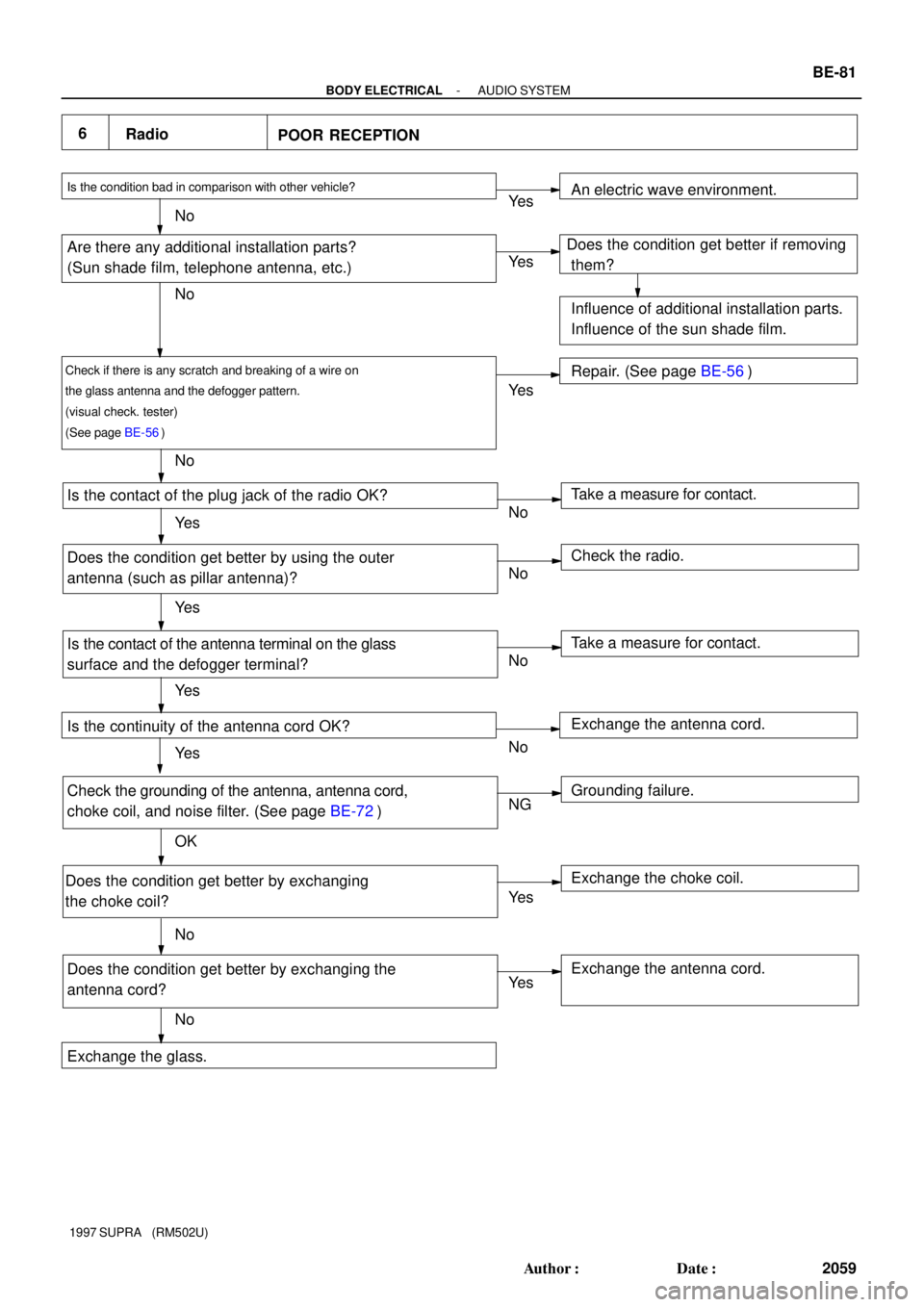
6
Radio
POOR RECEPTION
Is the condition bad in comparison with other vehicle?
Are there any additional installation parts?
(Sun shade film, telephone antenna, etc.)
Check if there is any scratch and breaking of a wire on
the glass antenna and the defogger pattern.
(visual check. tester)
(See page BE-56)
Is the contact of the plug jack of the radio OK?
Does the condition get better by using the outer
antenna (such as pillar antenna)?
Is the contact of the antenna terminal on the glass
surface and the defogger terminal?
Is the continuity of the antenna cord OK?
Check the grounding of the antenna, antenna cord,
choke coil, and noise filter. (See page BE-72)
Does the condition get better by exchanging
the choke coil?
Does the condition get better by exchanging the
antenna cord?Take a measure for contact. An electric wave environment.
Does the condition get better if removing
them?
Influence of additional installation parts.
Influence of the sun shade film.
Repair. (See page BE-56)
Check the radio.
Take a measure for contact.
Grounding failure. Exchange the antenna cord.
Exchange the choke coil.
Exchange the antenna cord. Ye s
No
Exchange the glass.Ye s
Ye s
Ye s
Ye s
Ye s
Ye s
Ye s
Ye s No
No
No
NoNo
No
No
No
NG
OK
- BODY ELECTRICALAUDIO SYSTEM
BE-81
2059 Author�: Date�:
1997 SUPRA (RM502U)
Page 568 of 1807
MA0688
Outside
Inside
- DIAGNOSTICSENGINE (2JZ-GTE)
DI-153
381 Author�: Date�:
1997 SUPRA (RM502U)
4 Check are filter.
PREPARATION:
Remove air filter.
CHECK:
Visually check that the air cleaner element is not dirty or exces-
sively oily.
HINT:
If necessary, clean element with compressed air. First blow from
inside throughly, then blow from outside of element.
NG Repair or replace.
OK
5 Check idle speed.
PREPARATION:
(a) Warm up engine to normal operating temperature.
(b) Switch off all accessories.
(c) Switch off air conditioning.
(d) Shift transmission into ºNº position.
(e) Connect the OBD II scan tool or TOYOTA hand-held tester to DLC3 on the vehicle.
CHECK:
Use CURRENT DATA to check the engine idle speed.
OK:
Idle speed: 650 ± 50 rpm
NG Proceed to matrix chart of problem symptoms
on page DI-169.
OK
Page 667 of 1807

S03235
Battery
B
R/B
No.22
2A
AM2
W-R W-R
IB147 6
Igniter
Switch
B-O
IJ11B-OB-OB-O B-O B-O
B-O
B-O
B-O
B-O
B-O
B-O
Spark Plug
Ignition Coil No.1
L-YG
Y
Y-B
Y-G
Y-R No.2
No.3
No.4
No.5
No.6 112
1
1
1
1
12
2
2
2
2
2
1
Noise Filter
BRECM
BR
EC
I24Igniter Tr
2
I22
6
5
4
10
11
12
I3 B
B
B
B
B
B
B
1
2
3
9
8
7
357
56
55
54
53
52
58
IGF5V IGT6 IGT5 IGT4IGT3 IGT2 IGT1
Tr1
5V
I3
I3
I3
I3
I3
I2 I3I3 I3 I3 I3I3
R-W
W-R
LG
B-R
L
R
R-Y DI-252
- DIAGNOSTICSENGINE (2JZ-GTE)
480 Author�: Date�:
1997 SUPRA (RM502U)
DTC P1300 Igniter Circuit Malfunction
CIRCUIT DESCRIPTION
The ECM determines the ignition timing, turns on Tr1 at a predetermined angle (°CA) before the desired
ignition timing and outputs an ignition signal (IGT) º1º to the igniter.
Since the width of the IGT signal is constant, the dwell angle control circuit in the igniter determines the time
the control circuit starts primary current flow to the ignition coil based on the engine rpm and ignition timing
one revolution ago, that is, the time the Tr2 turns on.
When it reaches the ignition timing, the ECM turns Tr1 off and outputs the IGT signal º0º.
This turns Tr2 off, interrupting the primary current flow and generating a high voltage in the secondary coil
which causes the spark plug to spark. Also, by the counter electromotive force generated when the primary
current is interrupted, the igniter sends an ignition confirmation signal (IGF) to the ECM.
The ECM stops fuel injection as a fail safe function when the IGF signal is not input to the ECM.
DTC No.DTC Detecting ConditionTrouble Area
P1300No IGF signal to ECM for 6 consecutive IGT signals during
engine running�Open or short in IGF or IGT circuit from igniter to ECM
�Igniter
�ECM
WIRING DIAGRAM
DI4TC-01
Page 1025 of 1807
![TOYOTA SUPRA 1997 Service Repair Manual Position of Parts in Engine Compartment
[2JZ-GTE]
R 1 Radiator Fan Motor No.1
R 2 Radiator Fan Relay No.1
R 3 Radiator Fan Relay No.2
R20 Radiator Fan Motor No.2
S 1 SFI Resistor
S 2 Starter
S 3 Start TOYOTA SUPRA 1997 Service Repair Manual Position of Parts in Engine Compartment
[2JZ-GTE]
R 1 Radiator Fan Motor No.1
R 2 Radiator Fan Relay No.1
R 3 Radiator Fan Relay No.2
R20 Radiator Fan Motor No.2
S 1 SFI Resistor
S 2 Starter
S 3 Start](/manual-img/14/57469/w960_57469-1024.png)
Position of Parts in Engine Compartment
[2JZ-GTE]
R 1 Radiator Fan Motor No.1
R 2 Radiator Fan Relay No.1
R 3 Radiator Fan Relay No.2
R20 Radiator Fan Motor No.2
S 1 SFI Resistor
S 2 Starter
S 3 Starter
S 5 Sub Throttle Position Sensor
S18 Sub Throttle Valve Motor
T 1 Theft Deterrent Horn
T 2 Throttle Position Sensor
T14 Turbo Pressure Sensor
V 2 VSV (EGR)
V 3 VSV (EVAP)
V 4 VSV (Exhaust Bypass Valve)
V 5 VSV (Exhaust Gas Control Valve)
V 6 VSV (Fuel Pressure Up)
V 7 VSV (Intake Air Control Valve)
V 8 VSV (Waste Gate Valve)
V10 Vehicle Speed Sensor No.1 (Combination Meter)
V11 Vehicle Speed Sensor No.2 (Electronically
Controlled Transmission)
W 1 Washer Motor I 1 Idle AIr Control Valve
I 2 Igniter
I 3 Igniter
I 6 Ignition Coil No.1
I 7 Ignition Coil No.2
I 8 Ignition Coil No.3
I 9 Ignition Coil No.4
I10 Ignition Coil No.5
I11 Ignition Coil No.6
I12 Injector No.1
I13 Injector No.2
I14 Injector No.3
I15 Injector No.4
I16 Injector No.5
I17 Injector No.6
K 1 Knock Sensor (on Front Side)
K 2 Knock Sensor (on Rear Side)
M 1 Mass Air Flow Meter
N 1 Noise Filter
O 1 O/D Direct Clutch Speed Sensor
O 2 Oil Pressure SW
P 1 PPS Solenoid
P 2 Park/Neutral Position SW, Back-Up Light SW and
A/T Indicator Light SW (A/T)
P13 Parking Light LH
25
G
Page 1027 of 1807
![TOYOTA SUPRA 1997 Service Repair Manual 27
G
Position of Parts in Engine Compartment
[2JZ-GE]
O 2 Oil Pressure SW
P 1 PPS Solenoid
P 2 Park/Neutral Position SW, Back-Up Light SW and
A/T Indicator Light SW (A/T)
P 3 Power Steering Pressure S TOYOTA SUPRA 1997 Service Repair Manual 27
G
Position of Parts in Engine Compartment
[2JZ-GE]
O 2 Oil Pressure SW
P 1 PPS Solenoid
P 2 Park/Neutral Position SW, Back-Up Light SW and
A/T Indicator Light SW (A/T)
P 3 Power Steering Pressure S](/manual-img/14/57469/w960_57469-1026.png)
27
G
Position of Parts in Engine Compartment
[2JZ-GE]
O 2 Oil Pressure SW
P 1 PPS Solenoid
P 2 Park/Neutral Position SW, Back-Up Light SW and
A/T Indicator Light SW (A/T)
P 3 Power Steering Pressure SW
P13 Parking Light LH
S 2 Starter
S 3 Starter
T 1 Theft Deterrent Horn
T 2 Throttle Position Sensor
V 1 VSV (ACIS)
V 2 VSV (EGR)
V 3 VSV (EVAP)
V 6 VSV (Fuel Pressure Up)
V10 Vehicle Speed Sensor No.1 (Combination Meter)
V11 Vehicle Speed Sensor No.2 (Electronically
Controlled Transmission)
W 1 Washer Motor H 1 Headlight Hi LH
H 2 Headlight Hi RH
H 3 Headlight Lo LH
H 4 Headlight Lo RH
H 8 Horn LH
H 9 Horn RH
I 1 Idle Air Control Valve
I 4 Igniter
I 5 Ignition Coil
I 12 Injector No.1
I 13 Injector No.2
I 14 Injector No.3
I 15 Injector No.4
I 16 Injector No.5
I 17 Injector No.6
K 1 Knock Sensor (on Front Side)
K 2 Knock Sensor (on Rear Side)
M 1 Mass Air Flow Meter
M 2 Main Heated Oxygen Sensor (Bank 1 Sensor 1)
M 3 Main Heated Oxygen Sensor (Bank 2 Sensor 1)
N 1 Noise Filter
Page 1044 of 1807

FRONT TURN SI GNAL
LIGHT RH AND
PARKING LIGHT RH
EFI NO. 2 RELAY
EFI MAIN RELAY
HE ATER RELAY
FRONT WIPER MOTOR
A/C CONDENSER FAN
MOTOR BRAKE FLUID LEVEL
WARNING SW
COMBINATION METER
ENGINE OIL
LEVEL SENSOR
NOISE FILTER
IGNITER PARKING LIGHT LH FRONT SIDE MARKE R
LIGHT LHDAYTIME
RUNNING
LIGHT RELAY
NO. 3
FRONT FOG LIGHT RH
EN GI NE H OOD
COURTESY SW
FR ON T TU RN S I G NA L
LIGHT LH
FRONT SIDE MA RKER
LIGHT RH
HE A DL I GHT LO R H
HEADLIGHT LO LH
ABS RELAY
A/ C DUAL PRESSURE
SW
ABS SOLENOID
RE LA Y
ABS ACTUATOR E 2
E 5 E 2 E 2 2
2
2
5
EB EA
HEATED OXYGEN
SEN SOR
(
BANK 1 SENSOR 2)
HEATED OXYGEN
SEN SOR
(
BANK 1 SENSOR 1)
ED EC II1 24
I17 E14I 2
IJ 1 18
(
E1)
(
E01)
(
E02) IC18 W- B
W- B
W- B
W- B W- BW- B
W- B
W- B
W- B
W- B
W- B
BR
BR
BR
BRBR W- B
W- B W- B
(
*3)W- B
(
*1)
W- B
(
*4)
W- B
W- B
W- B
W- B
W- B
W- BW- B
BR BR
BR
BR
BR
BR BR
BR BR
BR
W- B
(
*3)W- B
W- B
(
*3) E 7 : * 3
E20 : * 4E 2 : * 3
E18 : * 4E 2 : * 3
E18 : * 4
E 2 : * 3
E18 : * 4
E 5 : * 3
E19 : * 4
DA YTIME RUNNING
LIGHT RELAY
NO. 3 RA DIATOR FAN MOTOR
NO. 1
E11 : * 3
E24 : * 4W- B
W- B
W- B W- B
W- B
(
*1)E 2 : * 3
E18 : * 4
W- B
(
*3)
DA TA L I NK
CONNECTOR 2RADIATOR FAN
RELAY NO. 2 (
E) ENGI NE CO OLA NT TE MP .
SW
(
-S)
E 2 W- B
W- B W- B W- B W- B
W- B
W- B
BR E 2 : * 3
E18 : * 4
E 2
W- B
(
*1) (
*3)(
*3)(
*3)
(
*3)(
*3)
(
*3)
(
*3)ENGI NE CONTROL
MODULE W- B
BR
DA TA L I NK
CONNECTOR 1
DA TA LINK
CONNECTOR 3IJ15
BR
(
*4)
BR
(
*4)
E 9 : * 3
E21 : * 4
RA DIATOR FAN MOTOR
NO. 2W- B
(
*3) FRONT FOG LIGHT LH
W- B
THROTTLE
ECUDA TA L INK
CONNECTOR 3 BR
BR
BRBR
(
E03) BR (
*3)
W- B (
*3) (
E1)
(
E01)W- BW- B
(
*2) E 2
W- B
(
*1) W- B
(
*1)
IJ15
(
*3)
BR
BR
240
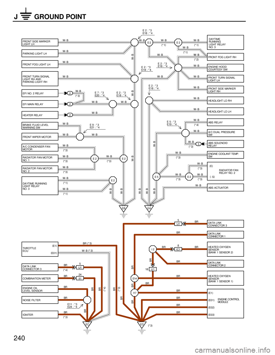
J GROUND POINT
Page 1066 of 1807
A 2B5B4B10 B11 B12 B6
B 77 B76 B57 B56 B55 B54 B53 B52 B58
B 26 B6B25 B27 B7A16A 4 A 3 B 7 B 8 B 9 B 3 B 2 B 1
G1
G- G2 NE NE-TACOGND IGF IGT6 IGT5 IGT4 IGT3 IGT2 IGT1+B IGC2 IGC3 IGC4 IGC5 IGC6 IGC1
STA NSW IGT1 IGT2 IGT3 IGT4 IGT5 IGT6 IGFE16 E11 E11 E11 E11 E11 E16
2 1
2 1
2 1
2 1
2 1
2 1
2 12121
EC 2 1
EDII1 29 B- O
B- W
BB-O B-O B-O B-O B-O B-O B-O
B- O
B- O
B- O
B- O
B- O
B- O
B- O G Y- R Y- GY- BY L- Y B- W
R- W
W- R
LG
B- R
L
R
R- Y
BR
B- O BR B- W B- W
BR BR
A A A
(
SHIELDED)
(
SHIELDED)IGNITION COIL
NO. 2
NOISE FILTER
IGNITER
ENGINE CONTROL MODULE
CAMSHAFT POSITION
SENSOR NO. 1CAMSHAFT POSI TION
SENSOR NO. 2CRANKSHAFT POSITION
SENSORTO TACHOMETER
[COMB. METER]
BR
A E 9 , E10BB I 2 , I 3A
I 7
N 1
C 3
C 2 C 1
IGNITION COIL
NO. 3 I 8
IGNITION COIL
NO. 4 I 9
IGNITION COIL
NO. 5 I10
IGNITION COIL
NO. 6 I11
IGNITION COIL
NO. 1 I 6
(
A/T)
(
A/ T)
JUNCTION
CONNECTOR J 2
B- R B- WW
(
SHIELDED)L
BR O
I17
BR
A
61
Page 1310 of 1807

EM0AV-02
P11544
(2)(3)
(1) EM-58
- ENGINE MECHANICAL (2JZ-GTE)ENGINE UNIT
1163 Author�: Date�:
1997 SUPRA (RM502U)
REMOVAL
1. REMOVE HOOD
2. REMOVE RADIATOR ASSEMBLY
(See page CO-22)
3. DRAIN ENGINE OIL
4. DRAIN FUEL FROM FUEL TANK
5. REMOVE NO.1 AIR HOSE
6. DISCONNECT CONTROL CABLES FROM
THROTTLE BODY
Disconnect these cables:
�Accelerator cable
�Cruise control actuator cable
7. REMOVE AIR CLEANER AND MAF METER
ASSEMBLY
(a) Remove the 3 bolts.
(b) Loosen the hose clamp, disconnect the air hose from the
intake air connector.
(c) Disconnect the MAF meter wire from the clamp on the air
cleaner case.
(d) Disconnect the MAF meter connector, and remove the air
cleaner and MAF meter assembly.
8. M/T:
REMOVE DRIVE BELT TENSIONER DAMPER
(See page EM-15)
9. REMOVE DRIVE BELT, FAN, FLUID COUPLING
ASSEMBLY AND WATER PUMP PULLEY
(See page CO-7)
10. REMOVE CHARCOAL CANISTER
11. DISCONNECT HEATER WATER HOSES
12. DISCONNECT BRAKE BOOSTER VACUUM HOSE
13. DISCONNECT EVAP HOSE
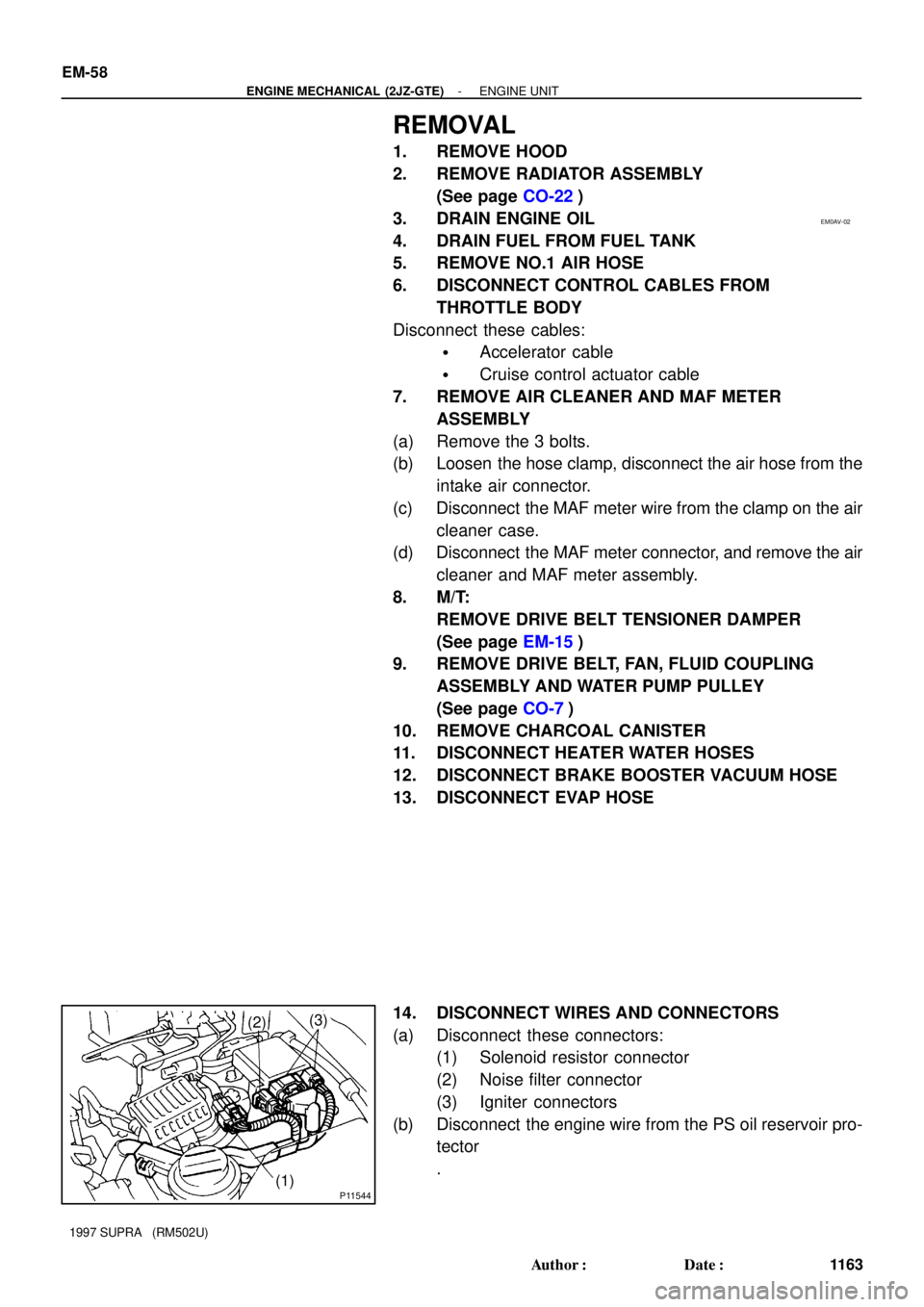
14. DISCONNECT WIRES AND CONNECTORS
(a) Disconnect these connectors:
(1) Solenoid resistor connector
(2) Noise filter connector
(3) Igniter connectors
(b) Disconnect the engine wire from the PS oil reservoir pro-
tector
.