Page 211 of 1807
Z18235
Outer Rear View Mirror LH
Mirror DefoggerA/C Control Panel Assembly
Defogger Switch
Outer Rear View Mirror RH
Mirror Defogger
Rear Window Defogger Defogger Relay R/B No.4
MIR-HTR Fuse DEFOG Fuse GAUGE Fuse J/B No.1
�
�
� �
� �
�
BE0EC-01
- BODY ELECTRICALDEFOGGER SYSTEM
BE-55
2033 Author�: Date�:
1997 SUPRA (RM502U)
DEFOGGER SYSTEM
LOCATION
Page 223 of 1807
Z18238
Outer Rear View Mirror LHOuter Rear View Mirror RH
Mirror Defogger Mirror Motor
Mirror Switch
PAD No.2 Fuse�
J/B No.1�
�
BE0EI-01
- BODY ELECTRICALPOWER MIRROR CONTROL SYSTEM
BE-67
2045 Author�: Date�:
1997 SUPRA (RM502U)
POWER MIRROR CONTROL SYSTEM
LOCATION
Page 265 of 1807
BO0QC-01
N19534
Outside Handle
Door Lock CylinderDoor Glass
Belt Moulding
Outer Rear View Mirror
Door Hinge
Door Check Door Window Upper Stop
Door Lock
Door Hinge
Weatherstrip
Glass Guide
Service Hole Cover Inside Panel
Frame
Window Regulator
Armrest Bracket
Setting Nut
Window Guide
Lower PlateInside Handle
Plate
Trim BoardInside Handle
Speaker
Power Window Switch
(Passenger's) Inside Handle Bezel
Power Window Master Switch
� Precoated part
7.4 (76, 67 in.´lbf)
11 (115, 8.3)
52 (530, 38)
25 (260, 19)
5.0 (51, 44 in.´lbf)
5.4 (55, 48 in.´lbf)7.4 (76, 67 in.´lbf)
N´m (kgf´cm, ft´lbf): Specified torque
- BODYFRONT DOOR
BO-7
2087 Author�: Date�:
1997 SUPRA (RM502U)
FRONT DOOR
COMPONENTS
Page 267 of 1807

N19388
- BODYFRONT DOOR
BO-9
2089 Author�: Date�:
1997 SUPRA (RM502U)
6. REMOVE WINDOW REGULATOR
(a) Disconnect the connector.
(b) Remove the bolt, 2 nuts and")
N19389
N19532
0 - 1.0 mm
(0 - 0.04 mm)
N19388
- BODYFRONT DOOR
BO-9
2089 Author�: Date�:
1997 SUPRA (RM502U)
6. REMOVE WINDOW REGULATOR
(a) Disconnect the connector.
(b) Remove the bolt, 2 nuts and window regulator.
Torque: 7.4 N´m (76 kgf´cm, 67 in.´lbf)
HINT:
At the time of reassembly, please refer to the following item.
Apply MP grease to the glass guide and rollers of the window
regulator.
7. REMOVE DOOR LOCK
(a) Disconnect the connector and clamp.
(b) Disconnect the link from the outside handle.
HINT:
At the time of reassembly, please refer to the following item.
After connecting the link, check that the clearance is within the
specification as shown in the illustration.
(c) Remove the 3 screws.
Torque: 5.0 N´m (51 kgf´cm, 44 in.´lbf)
HINT:
At the time of reassembly, please refer to the following item.
Apply adhesive to the 3 screws.
Part No.08833-00070, THREE BOND 1324 or equiva-
lent.
(d) Remove the door lock through the service hole.
HINT:
At the time of reassembly, please refer to the following item.
Apply MP grease to the sliding and rotating parts of the door
lock.
8. REMOVE THESE PARTS:
(a) Outside handle
(b) Door lock cylinder
(c) Outer rear view mirror
Page 287 of 1807
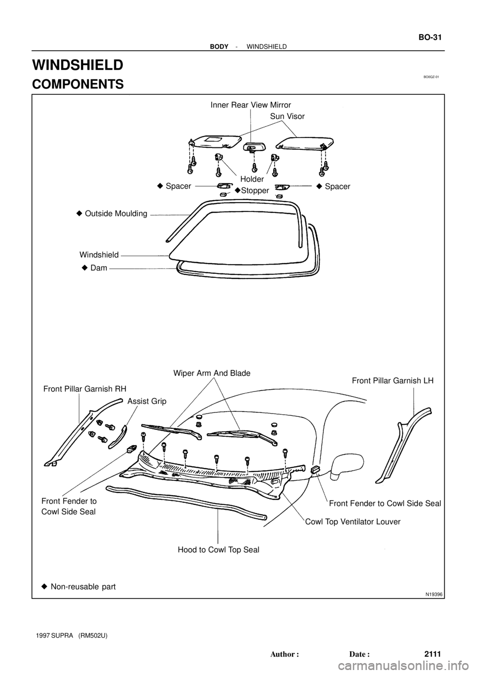
BO0QZ-01
N19396
Inner Rear View Mirror
� Spacer
� Spacer
�Stopper
HolderSun Visor
� Outside Moulding
Windshield
� Dam
Wiper Arm And Blade
Front Pillar Garnish RH
Assist GripFront Pillar Garnish LH
Front Fender to Cowl Side Seal
Cowl Top Ventilator Louver
Hood to Cowl Top Seal Front Fender to
Cowl Side Seal
� Non-reusable part
- BODYWINDSHIELD
BO-31
2111 Author�: Date�:
1997 SUPRA (RM502U)
WINDSHIELD
COMPONENTS
Page 288 of 1807

REMOVAL
1. REMOVE THESE PARTS:
(a) Inner rear view mirror
(b) Sun visors and holders
(c) Assist grip (Se")
BO0R0-01
N08453
BO5232
BO1689
BO-32
- BODYWINDSHIELD
2112 Author�: Date�:
1997 SUPRA (RM502U)
REMOVAL
1. REMOVE THESE PARTS:
(a) Inner rear view mirror
(b) Sun visors and holders
(c) Assist grip (See page BO-61)
HINT:
Tape a screwdriver tip before use.
(d) Front pillar garnishes (See page BO-61)
(e) Wiper arms and blades
(f) Cowl top ventilator louver
2. REMOVE WINDSHIELD MOULDING
(a) Using a knife, cut off the moulding as shown.
(b) Cut away the adhesive at the moulding installation area
as much as possible.
NOTICE:
Do not damage the body with the knife.
3. REMOVE WINDSHIELD GLASS
(a) Push piano wire through from the interior.
(b) Tie both wire ends to a wooden block or similar object.
HINT:
Apply adhesive tape to the outer surface of the glass to keep
the surface from being scratched.
NOTICE:
When separating the glass, take care not to damage the
paint and interior and exterior ornaments. To prevent
scratching the instrument panel when removing the wind-
shield, place a plastic sheet between the piano wire and
instrument panel.
(c) Cut the adhesive by pulling the piano wire around it.
(d) Remove the glass.
NOTICE:
Leave as much of the adhesive on the body as possible
when cutting off the glass.
Page 292 of 1807
N08452
BO-36
- BODYWINDSHIELD
2116 Author�: Date�:
1997 SUPRA (RM502U)
12. INSTALL WINDSHIELD MOULDING
Place the moulding onto the body and tap it by hand.
13. INSPECT FOR LEAKS AND REPAIR
(a) Do a leak test after the hardening time has elapsed.
(b) Seal any leak with auto glass sealer.
Part No. 08833-00030 or equivalent
14. INSTALL THESE PARTS:
(a) Cowl top ventilator louver
(b) Wiper arms and blades
Torque: 22 N´m (225 kgf´cm, 16 ft´lbf)
(c) Front pillar garnishes
(d) Assist grip
(e) Sun visors and holders
(f) Inner rear view mirror
Page 374 of 1807
 Junction Block No. 1Center Airbag Sensor Assembly Front Airbag Sensor LHFront Passenger Airbag Assembly Front Airbag Sensor RHSRS Warning Light
Spiral Cable
Locations")
Steering Wheel Pad
(with Airbag) Junction Block No. 1Center Airbag Sensor Assembly Front Airbag Sensor LHFront Passenger Airbag Assembly Front Airbag Sensor RHSRS Warning Light
Spiral Cable
Locations of SRS Components
HANDLING PRECAUTIONS ON RELATED COMPONENTS
1. SUPPLEMENTAL RESTRAINT SYSTEM (SRS)
Servicing vehicle with a Supplemental Restraint System (referrerd to as the SRS in the remainder of this
manual) installed.
When handling SRS components (removal, installation or inspection, etc.), always follow the directions
given in the repair manual for the relevant model year to prevent the occurrence of accidents and airbag
malfunction.
Also take the following precautions when repairing the body:
�Work must be started after 90 seconds or longer from the time the ignition switch is set to the LOCK
position and the negative (-) terminal cable is disconnected from the battery.
(The airbag system is equipped with a backup power source so that if work is started within 20 seconds
of disconnecting the negative (-) terminal cable of the battery, the airbag may be deployed.)
When the negative (-) terminal cable is disconnected from the battery, memory of the clock and audio
systems will be cancelled. So before starting work, make a record of the contents memorized by each
memory system. Then when work is finished, reset the clock and audio systems as before.
When the vehicle has tilt and telescopic steering, power seat, outside rear view mirror and power shoul-
der belt anchorage, which are all equipped with memory function, it is not possible to make a record of
the memory contents. So when the operation is finished, it will be necessary to explain this fact to the
customer, and request the customer to adjust the features and reset the memory.
�When using electric welding, first disconnect the SRS connector (yellow color and 2 pins) under the
steering column near the combination switch connector on the glove compartment finish plate and lower
the front scuff plate before starting work.
INTRODUCTIONIN-6