Page 56 of 1807
N19536
PLATE TYPE LIFT
AB
C L
Attachment
HINT:
Left and right set position
Front and rear set positionPlace the vehicle over the center of the lift.
Align the cushion gum ends of the plate
with the attachment lower ends (A, C).
Align the attachment upper end (B) with the
front jack supporting point (L). �
�
Attachment dimensions
85 mm (3.35 in.)
100 mm (3.94 in.)
200 mm (7.87 in.)70 mm (2.76 in.)
- INTRODUCTIONREPAIR INSTRUCTIONS
IN-9
9 Author�: Date�:
1997 SUPRA (RM502U)
Page 375 of 1807
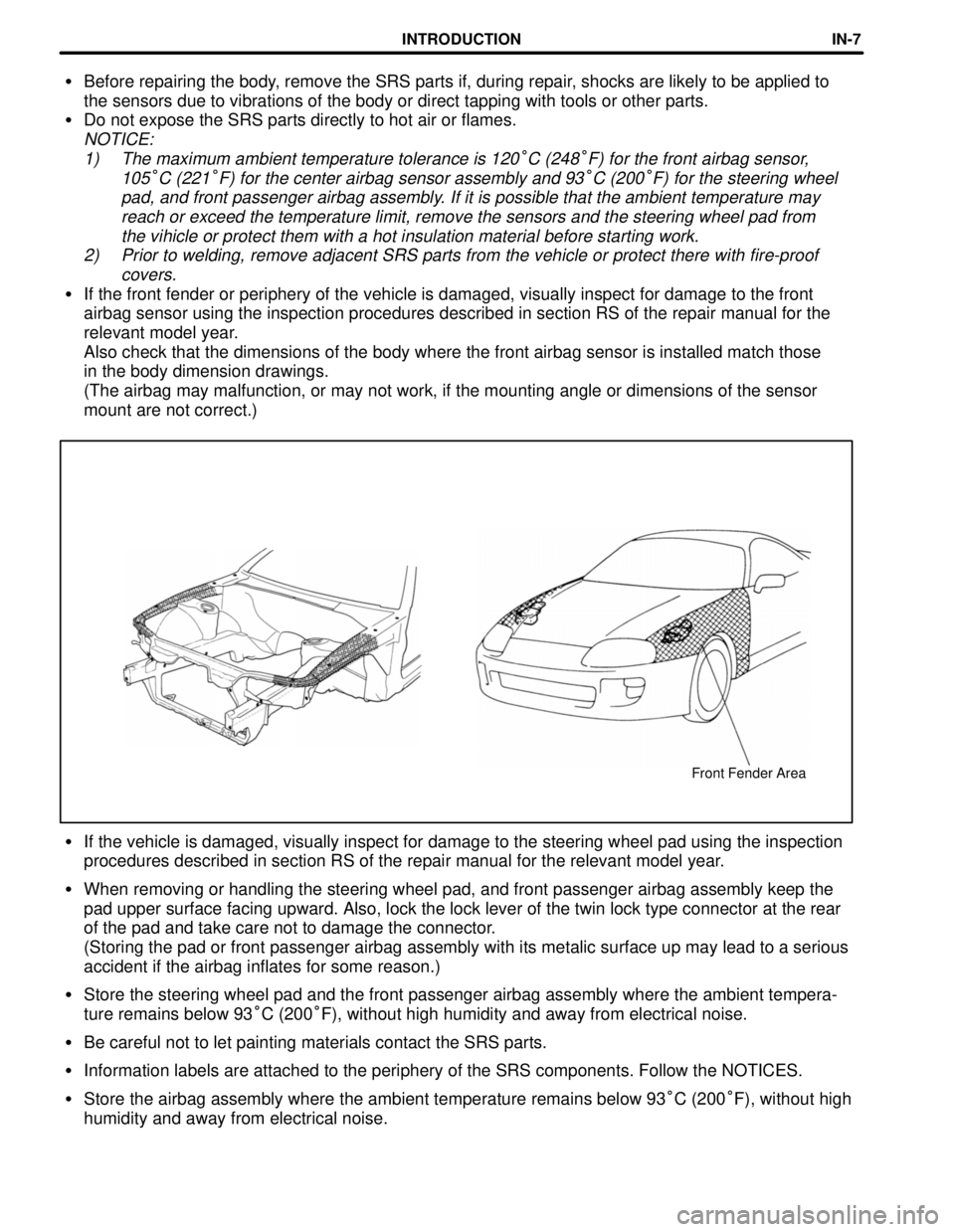
Front Fender Area
�Before repairing the body, remove the SRS parts if, during repair, shocks are likely to be applied to
the sensors due to vibrations of the body or direct tapping with tools or other parts.
�Do not expose the SRS parts directly to hot air or flames.
NOTICE:
1) The maximum ambient temperature tolerance is 120
°C (248°F) for the front airbag sensor,
105
°C (221°F) for the center airbag sensor assembly and 93°C (200°F) for the steering wheel
pad, and front passenger airbag assembly. If it is possible that the ambient temperature may
reach or exceed the temperature limit, remove the sensors and the steering wheel pad from
the vihicle or protect them with a hot insulation material before starting work.
2) Prior to welding, remove adjacent SRS parts from the vehicle or protect there with fire-proof
covers.
�If the front fender or periphery of the vehicle is damaged, visually inspect for damage to the front
airbag sensor using the inspection procedures described in section RS of the repair manual for the
relevant model year.
Also check that the dimensions of the body where the front airbag sensor is installed match those
in the body dimension drawings.
(The airbag may malfunction, or may not work, if the mounting angle or dimensions of the sensor
mount are not correct.)
�If the vehicle is damaged, visually inspect for damage to the steering wheel pad using the inspection
procedures described in section RS of the repair manual for the relevant model year.
�When removing or handling the steering wheel pad, and front passenger airbag assembly keep the
pad upper surface facing upward. Also, lock the lock lever of the twin lock type connector at the rear
of the pad and take care not to damage the connector.
(Storing the pad or front passenger airbag assembly with its metalic surface up may lead to a serious
accident if the airbag inflates for some reason.)
�Store the steering wheel pad and the front passenger airbag assembly where the ambient tempera-
ture remains below 93°C (200°F), without high humidity and away from electrical noise.
�Be careful not to let painting materials contact the SRS parts.
�Information labels are attached to the periphery of the SRS components. Follow the NOTICES.
�Store the airbag assembly where the ambient temperature remains below 93°C (200°F), without high
humidity and away from electrical noise.
INTRODUCTIONIN-7
Page 376 of 1807
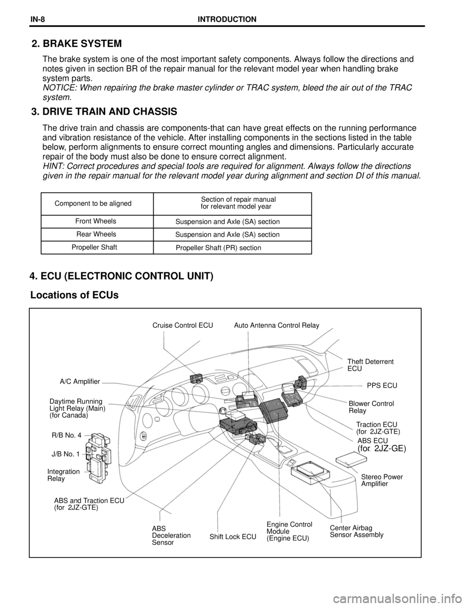
Shift Lock ECUEngine Control
Module
(Engine ECU)Center Airbag
Sensor Assembly ABS
Deceleration
Sensor ABS and Traction ECU
(for 2JZ-GTE)Stereo Power
Amplifier Integration
RelayJ/B No. 1Traction ECU
(for 2JZ-GTE)
R/B No. 4 Daytime Running
Light Relay (Main)
(for Canada)Blower Control
RelayPPS ECU A/C AmplifierTheft Deterrent
ECU Cruise Control ECU Auto Antenna Control Relay
ABS ECU
(for 2JZ-GE)
Component to be alignedSection of repair manual
for relevant model year
Front Wheels
Suspension and Axle (SA) section
Rear Wheels
Suspension and Axle (SA) section
Propeller Shaft
Propeller Shaft (PR) section
3. DRIVE TRAIN AND CHASSIS2. BRAKE SYSTEM
The brake system is one of the most important safety components. Always follow the directions and
notes given in section BR of the repair manual for the relevant model year when handling brake
system parts.
NOTICE: When repairing the brake master cylinder or TRAC system, bleed the air out of the TRAC
system.
The drive train and chassis are components-that can have great effects on the running performance
and vibration resistance of the vehicle. After installing components in the sections listed in the table
below, perform alignments to ensure correct mounting angles and dimensions. Particularly accurate
repair of the body must also be done to ensure correct alignment.
HINT: Correct procedures and special tools are required for alignment. Always follow the directions
given in the repair manual for the relevant model year during alignment and section DI of this manual.
4. ECU (ELECTRONIC CONTROL UNIT)
Locations of ECUs
INTRODUCTIONIN-8
Page 389 of 1807
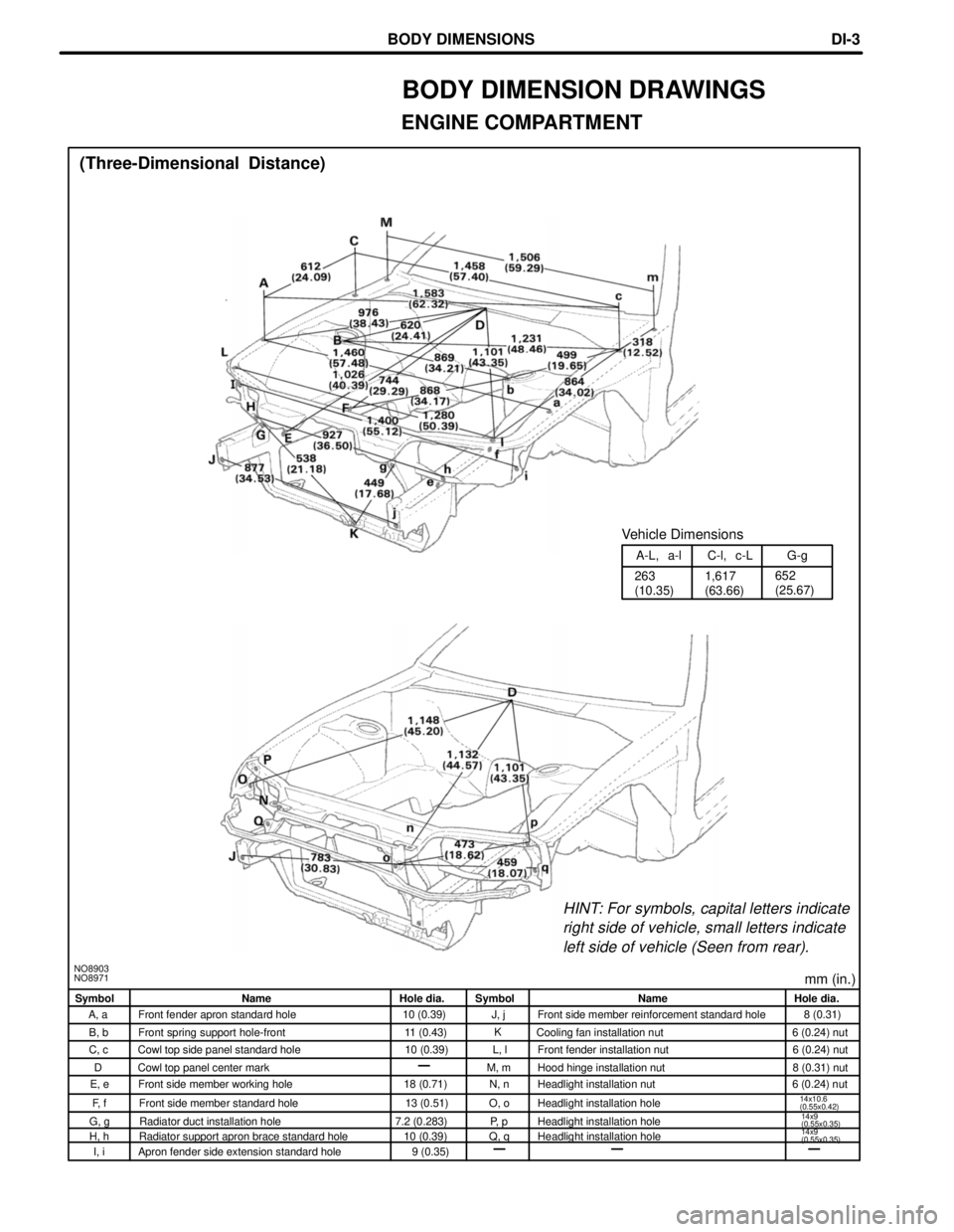
mm (in.)NO8903
NO8971
HINT: For symbols, capital letters indicate
right side of vehicle, small letters indicate
left side of vehicle (Seen from rear).
1,617
(63.66) 263
(10.35)652
(25.67) A-L, a-l C-l, c-L G-g
Vehicle Dimensions
(Three-Dimensional Distance)
Symbol Name Hole dia. Symbol Name Hole dia.
A, a Front fender apron standard hole 10 (0.39) J, j Front side member reinforcement standard hole 8 (0.31)
B, b Front spring support hole-front 11 (0.43) Cooling fan installation nut 6 (0.24) nut
C, c Cowl top side panel standard hole 10 (0.39) L, l Front fender installation nut 6 (0.24) nut
Cowl top panel center mark M, m Hood hinge installation nut 8 (0.31) nut
E, e Front side member working hole 18 (0.71) N, n Headlight installation nut 6 (0.24) nut
F, f Front side member standard hole 13 (0.51) O, o Headlight installation hole
14x10.6
(0.55x0.42)
G, g Radiator duct installation hole 7.2 (0.283) P, p Headlight installation hole
H, h Radiator support apron brace standard hole 10 (0.39) Q, q Headlight installation hole
I, i Apron fender side extension standard hole 9 (0.35)
BODY DIMENSION DRAWINGS
ENGINE COMPARTMENT
D
14x9
(0.55x0.35)
14x9
(0.55x0.35)
K
BODY DIMENSIONSDI-3
Page 392 of 1807
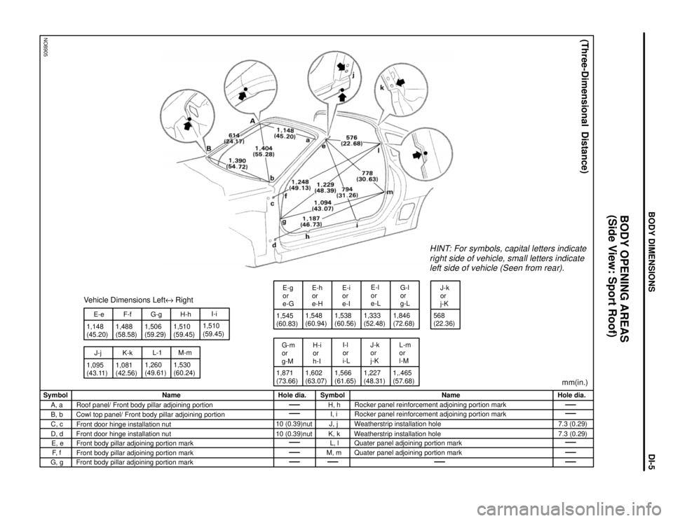
NO8905
1,148
(45.20)
J-j E-e
1,095
(43.11)1,488
(58.58)F-f
K-k
1,081
(42.56)G-g
1,260
(49.61)L-1Vehicle Dimensions LefteRight
1,506
(59.29)1,510
(59.45)
M-mH-h
1,530
(60.24)1,510
(59.45)I-i
1,545
(60.83)
G-m
or
g-ME-g
or
e-G
1,871
(73.66)1,602
(63.07) 1,548
(60.94)E-h
or
e-H
H-i
or
h-I1,538
(60.56)
I-l
or
i-L E-i
or
e-I
1,566
(61.65)E-l
or
e-L
J-k
or
j-K
1,227
(48.31) 1,333
(52.48)
L-m
or
l-MG-l
or
g-L
1,.465
(57.68)1,846
(72.68)
HINT: For symbols, capital letters indicate
right side of vehicle, small letters indicate
left side of vehicle (Seen from rear).
J-k
or
j-K
568
(22.36)
mm(in.)
(Three-Dimensional Distance)
Hole dia.
7.3 (0.29)
7.3 (0.29) Name
Rocker panel reinforcement adjoining portion mark
Rocker panel reinforcement adjoining portion mark
Weatherstrip installation hole
Weatherstrip installation hole
Quater panel adjoining portion mark
Quater panel adjoining portion mark Symbol
H, h
I, i
J, j
K, k
L, l
M, m Hole dia.
10 (0.39)nut
10 (0.39)nut Name
Roof panel/ Front body pillar adjoining portion
Cowl top panel/ Front body pillar adjoining portion
Front door hinge installation nut
Front door hinge installation nut
Front body pillar adjoining portion mark
Front body pillar adjoining portion mark
Front body pillar adjoining portion mark Symbol
A, a
B, b
C, c
D, d
E, e
F, f
G, g
BODY OPENING AREAS
(Side View: Sport Roof)
BODY DIMENSIONSDI-5
Page 393 of 1807
NO8906
HINT: For symbols, capital letters indicate
right side of vehicle, small letters indicate
left side of vehicle (Seen from rear).
(Three-Dimensional Distance)
mm (in.)Hole dia.
10 (0.39) Name
Back door opening trough / Quater panel adjoining portion
Lower back panel reinforcement standard hole
Roof side rail adjoining portion mark Symbol
D, d
E, e
F, f Hole dia.
8 (0.31)
9 (0.35) Name
Back door opening frame center mark
Damper stay installation hole-rear
Rear spring support hole-inner, front Symbol
A
B, b
C, c
BODY OPENING AREAS
(Rear View: Normal Roof)
BODY DIMENSIONSDI-6
Page 394 of 1807
HINT: For symbols, capital letters indicate
right side of vehicle, small letters indicate
left side of vehicle (Seen from rear).
(Three-Dimensional Distance)
mm (in.)Hole dia.
10 (0.39) Name
Back door opening trough / Quarter panel adjoining portion
Lower back panel reinforcement standard hole
Front body pillar adjoining portion mark Symbol
D, d
E, e
F, f Hole dia.
8 (0.31)
9 (0.35) Name
Back door opening frame center mark
Damper stay installation hole-rear
Rear spring support hole-inner, front Symbol
A
B, b
C, c
BODY OPENING AREAS
(Rear View: Sport Roof)
BODY DIMENSIONSDI-7
Page 395 of 1807
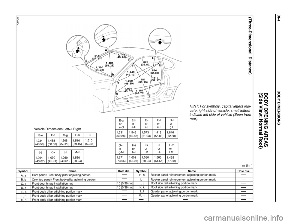
NO8904
J-j 1,234
(48.58)E-e
1,094
(43.07)1,488
(58.58)
K-kF-f
1,090
(42.91)
Vehicle Dimensions LefteRight
G-g
1,260
(49.61)L-l 1,506
(59.29)
1,530
(60.24)H-h
M-m 1,510
(59.45)1,510
(59.45)I-i1,531
(60.28)
G-m
or
g-ME-g
or
e-G
1,871
(73.66)1,602
(63.07)E-h
or
e-H
H-i
or
h-I 1,546
(60.87)
1,530
(60.24)I-k
or
i-KE-i
or
e-I
1,573
(61.93)1,418
(55.83)
1,566
(61.65)E-l
or
e-L
I-l
or
i-L1,846
(72.68)G-l
or
g-L
L-m
or
l-M
1,465
(57.68)
HINT: For symbols, capital letters indi-
cate right side of vehicle, small letters
indicate left side of vehicle (Seen from
rear).
(Three-Dimensional Distance)
mm (in. )Hole dia. Name
Rocker panel reinforcement adjoining portion mark
Rocker panel reinforcement adjoining portion mark
Roof side rail adjoining portion mark
Roof side rail adjoining portion mark
Quarter panel adjoining portion mark
Quarter panel adjoining portion mark Symbol
H, h
I, i
J, j
K, k
L, l
M, m Hole dia.
10 (0.39)nut
10 (0.39)nut Name
Roof panel/ Front body pillar adjoining portion
Cowl top panel/ Front body pillar adjoining portion
Front door hinge installation nut
Front door hinge installation nut
Front body pillar adjoining portion mark
Front body pillar adjoining portion mark
Front body pillar adjoining portion mark Symbol
A, a
B, b
C, c
D, d
E, e
F, f
G, g
BODY OPENING AREAS
(Side View: Normal Roof)
BODY DIMENSIONSDI-4