Page 82 of 1807

GLOSSARY OF SAE AND TOYOTA TERMS
This glossary lists all SAE-J1930 terms and abbreviations used in this manual in compliance")
IN04J-01
- INTRODUCTIONTERMS
IN-35
35 Author�: Date�:
1997 SUPRA (RM502U)
GLOSSARY OF SAE AND TOYOTA TERMS
This glossary lists all SAE-J1930 terms and abbreviations used in this manual in compliance with SAE rec-
ommendations, as well as their Toyota equivalents.
SAE
ABBREVIATIONSSAE TERMSTOYOTA TERMS
( )--ABBREVIATIONS
A/CAir ConditioningAir Conditioner
ACLAir CleanerAir Cleaner
AIRSecondary Air InjectionAir Injection (AI)
APAccelerator Pedal-
B+Battery Positive Voltage+B, Battery Voltage
BAROBarometric Pressure-
CACCharge Air CoolerIntercooler
CARBCarburetorCarburetor
CFIContinuous Fuel Injection-
CKPCrankshaft PositionCrank Angle
CLClosed LoopClosed Loop
CMPCamshaft PositionCam Angle
CPPClutch Pedal Position-
CTOXContinuous Trap Oxidizer-
CTPClosed Throttle Position-
DFIDirect Fuel Injection (Diesel)Direct Injection (DI)
DIDistributor Ignition-
DLC1
DLC2
DLC3Data Link Connector 1
Data Link Connector 2
Data Link Connector 31: Check Connector
2: Total Diagnosis Comunication Link (TDCL)
3: OBD II Diagnostic Connector
DTCDiagnostic Trouble CodeDiagnostic Code
DTMDiagnostic Test Mode-
ECLEngine Control Level-
ECMEngine Control ModuleEngine ECU (Electronic Control Unit)
ECTEngine Coolant TemperatureCoolant Temperature, Water Temperature (THW)
EEPROMElectrically Erasable Programmable Read Only Memory
Electrically Erasable Programmable Read Only Memory
(EEPROM),
Erasable Programmable Read Only Memory (EPROM)
EFEEarly Fuel EvaporationCold Mixture Heater (CMH), Heat Control Valve (HCV)
EGRExhaust Gas RecirculationExhaust Gas Recirculation (EGR)
EIElectronic IgnitionDistributorless Ignition (DI)
EMEngine ModificationEngine Modification (EM)
EPROMErasable Programmable Read Only MemoryProgrammable Read Only Memory (PROM)
EVAPEvaporative EmissionEvaporative Emission Control (EVAP)
FCFan Control-
FEEPROMFlash Electrically Erasable Programmable
Read Only Memory-
FEPROMFlash Erasable Programmable Read Only Memory-
FFFlexible Fuel-
FPFuel PumpFuel Pump
GENGeneratorAlternator
GNDGroundGround (GND)
Page 530 of 1807
CO08L-02
- COOLINGWATER PUMP
CO-3
1416 Author�: Date�:
1997 SUPRA (RM502U)
WATER PUMP
COMPONENTS
Page 531 of 1807
CO-4
- COOLINGWATER PUMP
1417 Author�: Date�:
1997 SUPRA (RM502U)
Page 532 of 1807
B01771
Air Cleaner and MAF Meter Assembly
No.1 Air Hose
Air Cleaner Duct
Upper Radiator Support
Radiator Assembly
Radiator Reservoir Hose
Electric Cooling
Fan Connector
ECT Switch
Connector
No.2 Fan Shroud
No.2 Air Tube Lower
Radiator
Support
Hose Clamp
Oil Cooler Tube
Engine Under Cover Drive Belt
A/T
x 16Battery
Insulator
Water Pump Pulley
Fan and Fluid Coupling Assembly
PS Pump Pulley
Battery Tray
Battery
MAF Meter Connector
Hold-Down
Clamp
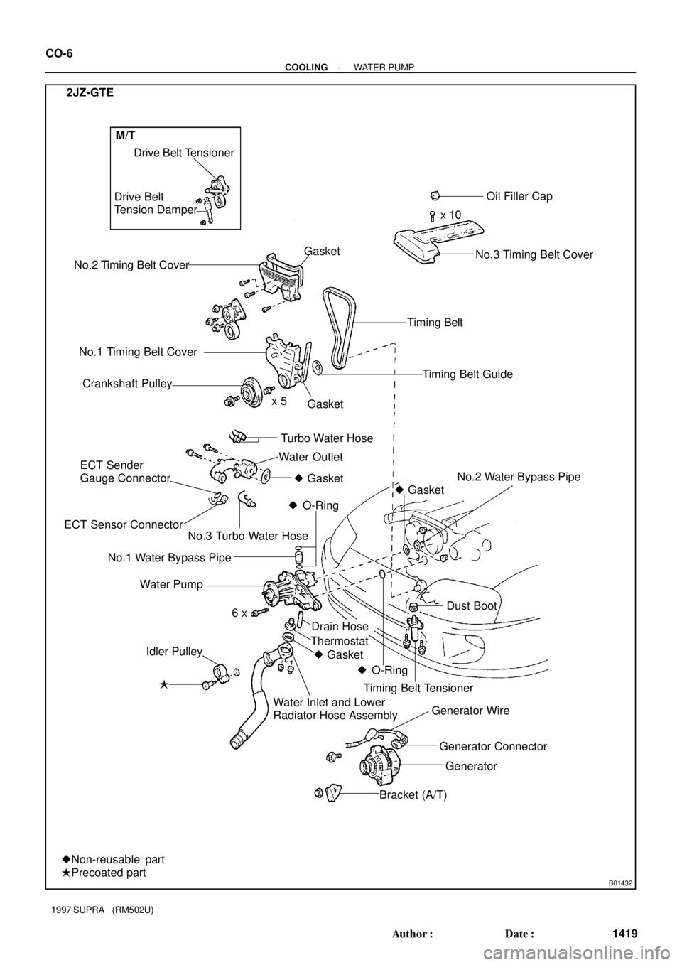
2JZ-GTE
- COOLINGWATER PUMP
CO-5
1418 Author�: Date�:
1997 SUPRA (RM502U)
Page 533 of 1807
B01432
No.2 Timing Belt CoverDrive Belt Tensioner
No.1 Timing Belt Cover
Crankshaft PulleyOil Filler Cap
x 10
Timing Belt
Timing Belt Guide
No.2 Water Bypass Pipe
� Idler PulleyGasket
Drain Hose Water Pump
x 5
Dust Boot � Gasket
� O-Ring
� O-Ring � Gasket Thermostat
Timing Belt Tensioner
Generator Connector Generator Wire
Generator
Bracket (A/T) Water Inlet and Lower
Radiator Hose Assembly
�Precoated part
�Non-reusable part
6 x 2JZ-GTE
Gasket
Water Outlet
ECT Sender
Gauge Connector
ECT Sensor ConnectorTurbo Water Hose Drive Belt
Tension Damper
No.3 Timing Belt Cover
No.3 Turbo Water Hose� Gasket
No.1 Water Bypass Pipe
M/T
CO-6
- COOLINGWATER PUMP
1419 Author�: Date�:
1997 SUPRA (RM502U)
Page 534 of 1807

REMOVAL
1. 2JZ-GTE:
REMOVE NO.1 AIR HOSE
2. 2JZ-GE:
REMOVE AIR CLEANER, MAF METER AND INTAKE
AIR CONNECTO")
CO08M-02
P12278
P12300Turn
- COOLINGWATER PUMP
CO-7
1420 Author�: Date�:
1997 SUPRA (RM502U)
REMOVAL
1. 2JZ-GTE:
REMOVE NO.1 AIR HOSE
2. 2JZ-GE:
REMOVE AIR CLEANER, MAF METER AND INTAKE
AIR CONNECTOR PIPE ASSEMBLY
(See page EM-57)
3. 2JZ-GTE:
REMOVE AIR CLEANER AND MAF METER
ASSEMBLY (See page EM-58)
4. REMOVE RADIATOR ASSEMBLY
(See page CO-22)
5. 2JZ-GTE M/T:
REMOVE DRIVE BELT TENSIONER DAMPER
(See page EM-15)
6. REMOVE DRIVE BELT, FAN, FLUID COUPLING
ASSEMBLY AND WATER PUMP PULLEY
(a) Loosen the 4 nuts holding the fluid coupling to the water
pump.
(b) Loosen the drive belt tension by turning the drive belt ten-
sioner clockwise, and remove the drive belt.
(c) Remove the 4 nuts, the fan, fluid coupling assembly and
water pump pulley.
7. REMOVE WATER INLET, LOWER RADIATOR HOSE
ASSEMBLY AND THERMOSTAT
(See page CO-14)
8. REMOVE TIMING BELT
(2JZ-GE: See page EM-13)
(2JZ-GTE: See page EM-15)
9. REMOVE IDLER PULLEY
(2JZ-GE: See page EM-13)
(2JZ-GTE: See page EM-15)
10. 2JZ-GTE:
DISCONNECT TURBO WATER HOSES FROM
WATER OUTLET
Page 535 of 1807

Z16746
O-Ring
Water Bypass Outlet
NO.1 Water
Bypass Pipe 2JZ-GE
Z16764
2JZ-GTE
Z16745
2JZ-GE
Z16930
2JZ-GE
No.2 Water Bypass Pipe
2JZ-GTE
No.2 Water Bypass Pipe
No.3 Turbo Water Hose
CO-8
- COOLINGWATER PUMP
1421 Author�: Date�:
1997 SUPRA (RM502U)
11. 2JZ-GE:
REMOVE WATER BYPASS OUTLET AND NO.1
WATER BYPASS PIPE
(a) Remove the 2 bolts, water bypass outlet and No.1 water
bypass pipe.
(b) Remove the 3 O-rings from the water bypass outlet and
No.1 water bypass pipe.
12. 2JZ-GTE:
REMOVE WATER OUTLET AND NO.1 WATER
BYPASS PIPE
(a) Disconnect the ECT sensor and sender gauge connec-
tors.
(b) Remove the 2 bolts, water outlet and gasket.
(c) Remove the No.1 water bypass pipe and 2 O-rings.
13. REMOVE WATER PUMP
(a) Loosen the nut and remove the bolt, and slightly slide the
generator from the water pump.
(b) 2JZ-GE:
Remove the bolt, and disconnect the clamp bracket.
(c) 2JZ-GE:
Remove the bolt, and disconnect the connector bracket
(for crankshaft position sensor connector).
(d) Remove the 2 nuts, and disconnect the No.2 water by-
pass pipe from the water pump.
(e) 2JZ-GTE:
Disconnect the No.3 turbo water hose from the water
pump.
Page 536 of 1807
P25846
Drain Hose
- COOLINGWATER PUMP
CO-9
1422 Author�: Date�:
1997 SUPRA (RM502U)
(f) Remove the 6 bolts, water pump and gasket.
(g) Remove the drain hose.
(h) Remove the O-ring from the cylinder block.