Page 169 of 1807
BE1L3-01
Z09193
Z14750
OFF
ON
N16845
- BODY ELECTRICALIGNITION SWITCH AND KEY UNLOCK WARNING
SWITCHBE-13
1991 Author�: Date�:
1997 SUPRA (RM502U)
INSPECTION
1. INSPECT IGNITION SWITCH CONTINUITY
Switch positionTester connectionSpecified condition
LOCK-No continuity
ACC5 - 7Continuity
ON4 - 5 - 7, 2 - 3Continuity
START4 - 7 - 8, 1 - 2 - 3Continuity
If continuity is not as specified, replace the switch.
2. INSPECT KEY UNLOCK WARNING SWITCH CONTI-
NUITY
ConditionTester connectionSpecified condition
SW OFF
(Key removed)-No continuity
SW ON (Key set)1 - 2Continuity
If continuity is not as specified, replace the switch.
3. Key Unlock Warning System:
INSPECT INTEGRATION RELAY OPERATION
(a) Connect the positive (+) lead from the battery to terminal
1, the negative (-) lead to terminals 5 and 10..
(b) Check the buzzer sounds when the negative (-) lead from
the battery is connected to terminal 6..
If operation is not as specified, replace the relay.
Page 170 of 1807

4. INSPEC")
Z07373
Junction Block Side
Connector ºAº
Wire Harness Side
Connector ºBº BE-14
- BODY ELECTRICALIGNITION SWITCH AND KEY UNLOCK WARNING
SWITCH
1992 Author�: Date�:
1997 SUPRA (RM502U)
4. INSPECT RELAY CIRCUIT
Light Auto Turn Off System:
Remove the relay from junction block and inspect the connec-
tors on the wire harness and junction block side, as shown in
the chart.
Tester connectionConditionSpecified condition
A6 - GroundDriver's door courtesy switch OFFNo continuity
A6 - GroundDriver's door courtesy switch ONContinuity
A10 - GroundConstantContinuity
B1 - GroundLight control switch position OFF or TAILNo continuity
B1 - GroundLight control switch position HEADContinuity
B4 - GroundLight control switch position OFFNo continuity
B4 - GroundLight control switch position TAIL or HEADContinuity
A1 - GroundConstantBattery positive voltage
A7 - GroundIgnition switch position LOCK or ACCNo voltage
A7 - GroundIgnition switch position ONBattery positive voltage
B2 - GroundConstantBattery positive voltage
B3 - GroundConstantBattery positive voltage
If the circuit is as specified, try replacing the relay with a new
one.
If the circuit not as specified, inspect the circuits connected to
other parts.
Page 185 of 1807
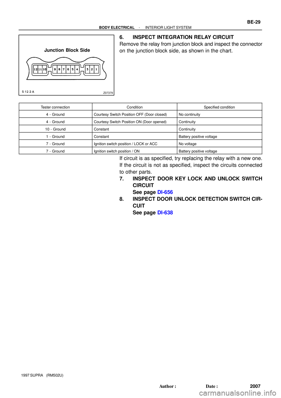
Z07379
Junction Block Side
- BODY ELECTRICALINTERIOR LIGHT SYSTEM
BE-29
2007 Author�: Date�:
1997 SUPRA (RM502U)
6. INSPECT INTEGRATION RELAY CIRCUIT
Remove the relay from junction block and inspect the connector
on the junction block side, as shown in the chart.
Tester connectionConditionSpecified condition
4 - GroundCourtesy Switch Position OFF (Door closed)No continuity
4 - GroundCourtesy Switch Position ON (Door opened)Continuity
10 - GroundConstantContinuity
1 - GroundConstantBattery positive voltage
7 - GroundIgnition switch position / LOCK or ACCNo voltage
7 - GroundIgnition switch position / ONBattery positive voltage
If circuit is as specified, try replacing the relay with a new one.
If the circuit is not as specified, inspect the circuits connected
to other parts.
7. INSPECT DOOR KEY LOCK AND UNLOCK SWITCH
CIRCUIT
See page DI-656
8. INSPECT DOOR UNLOCK DETECTION SWITCH CIR-
CUIT
See page DI-638
Page 207 of 1807

26. INSPECT INTEGRATION RELAY OPERATION
(a) Connect the p")
N08953
N08954
BE6219
Junction Block Side
Connector ºAº
- BODY ELECTRICALCOMBINATION METER
BE-51
2029 Author�: Date�:
1997 SUPRA (RM502U)
26. INSPECT INTEGRATION RELAY OPERATION
(a) Connect the positive (+) lead from the battery to terminals
1 and 7.
(b) Connect the positive (+) lead from the battery to terminal
9 through a 3.4 W test bulb.
(c) Check that the test bulb lights up and buzzer sounds for
4 - 8 seconds when the negative (-) lead from the battery
is connected to terminal 10.
(d) Check that the buzzer sounding in (c) stops when the
negative (-) lead from the battery is connected to terminl
8.
If operation is not as specified, replace the integration relay.
27. INSPECT RELAY CIRCUIT
Remove the relay from the junction block No. 1 and inspect the
connectors on the junction block side.
Tester connectionConditionSpecified condition
4 - GroundDriver's door openContinuity
4 - GroundDriver's door closeNo continuity
5 - GroundIgnition key SetContinuity
5 - GroundIgnition key removeNo continuity
8 - GroundDriver's seat belt fastenContinuity
8 - GroundDriver's seat belt unfastenNo continuity
10 - GroundConstantContinuity
1 - GroundConstantBattery positive voltage
9 - GroundIgnition switch position ONBattery positive voltage
9 - GroundIgnition switch position LOCK or ACCNo Voltage
If circuit is not as specified, tray replacing the relay with a new
one.
Page 487 of 1807

FOR THE TOYOTA DEALER
COLLISION REPAIR INFORMATION
TITLE: SRS AIRBAG COMPONENT REPLACEMENT PAGE 1 of 6
SECTION: ELECTRICAL BULLETIN #79
MODELS: ALL
DATE: AUGUST 1997
After an airbag has been deployed during a collision, it will be necessary to replace certain
components of the airbag system. Technicians can identify these parts by using the
attached matrix.
If the airbag does not deploy, yet the combination meter (airbag warning light) stays on for
more that 10 seconds after the key is turned to the ªACCº or ªONº position, it is necessary
to perform a diagnostic test. Always refer to the Toyota repair manual for the correct repair
procedure.
The attached information includes:
�A matrix indicating components requiring replacement (pages 2±4).
�Parts replacement note (page 5).
�An example repair manual page outlining the diagnostic procedure available in
each model specific repair manual (page 6).
Toyota recommends the use of electrical repair kit (P/N 00002±04200±01) for any wiring
repairs. This kit includes a selection of numerous repair connectors, terminal ends, a repair
procedures manual and special tools specific to Toyota. The
replacement electrical wire
and connector (from the wire harness to the front sensors) is P/N 82988±24010.
Toyota also offers a video package which shows the operation of the SRS airbag system
(P/N 00401±42994).
CAUTION: SRS Airbag service work can be performed only AFTER 90 SECONDS
from the time the ignition switch is turned to the ªlockº position and the
negative (±) terminal cable is disconnected from the battery.
NOTE: PLEASE ROUTE THIS BULLETIN TO YOUR COLLISION REPAIR CENTER
MANAGER!
Page 497 of 1807

FOR THE TOYOTA DEALER
COLLISION REPAIR INFORMATION
TITLE: SRS AIRBAG COMPONENT REPLACEMENT PAGE 1 of 6
SECTION: ELECTRICAL BULLETIN #79
MODELS: ALL
DATE: AUGUST 1997
After an airbag has been deployed during a collision, it will be necessary to replace certain
components of the airbag system. Technicians can identify these parts by using the
attached matrix.
If the airbag does not deploy, yet the combination meter (airbag warning light) stays on for
more that 10 seconds after the key is turned to the ªACCº or ªONº position, it is necessary
to perform a diagnostic test. Always refer to the Toyota repair manual for the correct repair
procedure.
The attached information includes:
�A matrix indicating components requiring replacement (pages 2±4).
�Parts replacement note (page 5).
�An example repair manual page outlining the diagnostic procedure available in
each model specific repair manual (page 6).
Toyota recommends the use of electrical repair kit (P/N 00002±04200±01) for any wiring
repairs. This kit includes a selection of numerous repair connectors, terminal ends, a repair
procedures manual and special tools specific to Toyota. The
replacement electrical wire
and connector (from the wire harness to the front sensors) is P/N 82988±24010.
Toyota also offers a video package which shows the operation of the SRS airbag system
(P/N 00401±42994).
CAUTION: SRS Airbag service work can be performed only AFTER 90 SECONDS
from the time the ignition switch is turned to the ªlockº position and the
negative (±) terminal cable is disconnected from the battery.
NOTE: PLEASE ROUTE THIS BULLETIN TO YOUR COLLISION REPAIR CENTER
MANAGER!
Page 910 of 1807
N19900
1K
1J
IJ2P2P2
C9C9IJ1
EA122
2IB2IF2
I19I19IB1
2
2A
S2S3 4
6
87 B1365
1223
1
2
3510Theft Deterrent and
Door Lock ECU
EA2
EA3
4Starter Relay MAINL-OSRLY
25
Clutch Start Switch(M/T)
21AM2 J/B No.1 STR/B No.2
2
1
2JZ-GTE
2JZ-GE
Battery1
2 B
BL-O
L-O B-WB-WW-R
W-R W-B
B
B B 1 Ignition
SwitchT13
Park/Neutral Start Switch
1
1 B
(A/T)
12
- DIAGNOSTICSTHEFT DETERRENT SYSTEM
DI-619
847 Author�: Date�:
1997 SUPRA (RM502U)
Starter Relay Circuit
CIRCUIT DESCRIPTION
When the theft deterrent system is activated, contact ºaº in the ECU becomes open, creating an open circuit
in terminal ST circuit and making the starter inoperative (starter cut).
In this condition, if one of the following operations is done, the contact ºaº in the ECU is grounded, thus can-
celing the starter cut:
(1) The front LH and RH door is unlocked with a key.
WIRING DIAGRAM
DI4X2-01
Page 912 of 1807
I02710
I02710
Theft Deterrent and
Door Lock ECU R/B No.2
HORN Relay
R/B No2.Horn Switch
HornL-R
L-B HAZ-HORN
BatteryHORN
L-BL-R
L-R W
22
2 2
2
2A 11
1116
14
L-R
L-B 3IB2IF2
24
BT13
- DIAGNOSTICSTHEFT DETERRENT SYSTEM
DI-621
849 Author�: Date�:
1997 SUPRA (RM502U)
Horn Relay Circuit
CIRCUIT DESCRIPTION
When the theft deterrent system is activated, it causes the Tr in the ECU to switch on and off in approximately
0.2 sec. cycles. This switches the horn relay on and off, thus the horn blow (See the wiring diagram below).
In this condition, if any of the following operations is done, the Tr in the ECU goes off and the horn relay
switches off, thus the horns stop blowing:
(1) The front LH or RH door is unlocked with a key.
(2) The ignition switch is turned to the ACC or ON position.
(3) Approximately 1 minute elapses.
WIRING DIAGRAM
DI4X3-01


21AM2 J/B No.1")
