Page 115 of 1807

AC0Q1-01
N13793
Charging Cylinder High Pressure
Service Valve Low Pressure
Service ValvePush
Air
N13792
Gas Leak
Detector AC-12
- AIR CONDITIONINGAIR CONDITIONING SYSTEM
2160 Author�: Date�:
1997 SUPRA (RM502U)
CHARGING
1. INSTALL CHARGING CYLINDER
HINT:
When handling the charging cylinder, always follow the direc-
tions given in the instruction manual.
(a) Charge the proper amount of refrigerant into the charging
cylinder.
(b) Connect the center hose to the charging cylinder.
CAUTION:
Do not open both high and low hand valves of manifold
gauge set.
(c) Open the valve of charging cylinder.
(d) Press the valve core on the side of manifold gauge and
expel the air inside of the center hose.
2. INSPECT REFRIGERATION SYSTEM FOR LEAKS
(a) Open the high pressure hand valve and charge refriger-
ant.
(b) When the low pressure gauge indicates 98 kPa
(1 kgf/cm
2, 14 psi) close the high pressure hand valve.
(c) Using a gas leak detector, check the system for leakage.
If leak is found, repair the faulty component or connection.
CAUTION:
Use the refrigerant recovery/ recycling machine to recover
the refrigerant whenever replacing parts.
Page 116 of 1807
N13790
Low Pressure
Service Valve
High Pressure
Service Valve
- AIR CONDITIONINGAIR CONDITIONING SYSTEM
AC-13
2161 Author�: Date�:
1997 SUPRA (RM502U)
3. CHARGE REFRIGERANT INTO REFRIGERANT SYS-
TEM
If there is no leak after refrigerant leak check, charge the proper
amount of refrigerant into refrigeration system.
CAUTION:
�Never run the engine when charging the system
through the high pressure side.
�Do not open the low pressure hand a valve when the
system is being charged with liquid refrigerant.
(a) Open the high pressure hand valve fully.
(b) Charge specified amount of refrigerant, then close the
high pressure hand valve.
HINT:
A fully charged system is indicated by the sight glass being free
of any bubbles.
4. REMOVE MANIFOLD GAUGE SET
(a) Close both hand valves of manifold gauge set.
(b) Disconnect the quick disconnect adapters from the ser-
vice valves.
5. INSTALL CAPS TO SERVICE VALVES ON REFRIGER-
ANT LINES
Page 681 of 1807

VSV for Exhaust
Bypass Valve
Actuator
(for Exhaust
Bypass Valve)
VSV for Intake Air Control Valve
Actuator (for Intake")
S03236
VSV for Exhaust Gas Control Valve
Actuator (for Exhaust Gas Control Valve)
VSV for Exhaust
Bypass Valve
Actuator
(for Exhaust
Bypass Valve)
VSV for Intake Air Control Valve
Actuator (for Intake Air Control Valve) Exhaust Manifold
Intake Manifold CAC Air Bypass Valve Actuator
(for Waste Gate Valve)Air
Cleaner VSV for Waste
Gate Valve
Waste Gate
Valve
ECM
DI-266
- DIAGNOSTICSENGINE (2JZ-GTE)
494 Author�: Date�:
1997 SUPRA (RM502U)
DTC P1511 Boost Pressure Low Malfunction
CIRCUIT DESCRIPTION
To control maximum turbocharging pressure the turbocharger system includes a waste gate valve or exhaust
bypass valve controlled by an actuator. The actuator is controlled by the manifold pressure which is duty
controlled by the VSV based on signals from the ECM.
DTC No.DTC Detecting ConditionTrouble Area
P1511
Under the following conditions (a), (b) and (c):
(a) After the engine is warmed up
(b) Engine rotation speed is 2,600 rpm is more
(c) At the time of WOT, under the condition with +150 mmHg or
less of intake pipe pressure
(2 trip detection logic)�Actuator (for waste gate valve, intake air control valve, ex-
haust gas control valve, and exhaust bypass valve)
�Short in VSV for waste gate valve, intake air control valve,
exhaust gas control valve and exhaust bypass valve circuit
�ECM
�Air intake (leakage or clogging)
DI4TI-01
Page 689 of 1807

VSV for Exhaust
Bypass Valve
Actuator
(for Exhaust
Bypass Valve)
VSV for Intake Air Control Valve
Actuator (for Intake")
S03236
VSV for Exhaust Gas Control Valve
Actuator (for Exhaust Gas Control Valve)
VSV for Exhaust
Bypass Valve
Actuator
(for Exhaust
Bypass Valve)
VSV for Intake Air Control Valve
Actuator (for Intake Air Control Valve) Exhaust Manifold
Intake Manifold CAC Air Bypass Valve Actuator
(for Waste Gate Valve)Air
Cleaner VSV for Waste
Gate Valve
Waste Gate
Valve
ECM
DI-274
- DIAGNOSTICSENGINE (2JZ-GTE)
502 Author�: Date�:
1997 SUPRA (RM502U)
DTC P1512 Boost Pressure High Malfunction
CIRCUIT DESCRIPTION
To control maximum turbocharging pressure the turbocharger system includes a waste gate valve or exhaust
bypass valve controlled by an actuator. The actuator is controlled by the manifold pressure which is duty
controlled by the VSV based on signals from the ECM.
If the ECM detects the below diagnosis conditions, it operates the fail safe function in which the ECM stops
fuel injection.
DTC No.DTC Detecting ConditionTrouble Area
P1512
Under the following conditions (a), (b) and (c):
(a) After the engine is warmed up
(b) Engine rotation speed 3,400 rpm or less
(c) Under the condition with +740 mmHg or more of intake pipe
pressure
(2 trip detection logic)
�Actuator (for waste gate valve and exhaust bypass valve)
�Short in VSV for waste gate valve and exhaust bypass valve
circuit
�ECM
DI4TJ-01
Page 767 of 1807
F02629F03331F03332F03333
ON
NORMAL ABS
(2JZ-GE Enegine):
SPORT ABS
(2JZ-GTE Enegine):IG1GND
GND
IG1 (+)
(-)
(+)
(-)
DI-476
- DIAGNOSTICSANTI-LOCK BRAKE SYSTEM
704 Author�: Date�:
1997 SUPRA (RM502U)
INSPECTION PROCEDURE
1 Check battery positive voltage.
OK:
Voltage: 10 - 14 V
NG Check and repair the charging system.
OK
2 Check voltage between terminals IG1 and GND of ABS ECU connector.
PREPARATION:
Remove ABS ECU with connectors still connected.
CHECK:
(a) Turn ignition switch ON.
(b) Measure voltage between terminals IG1 and GND of ABS
ECU connector.
OK:
Voltage: 10 - 14 V
OK Check and replace ABS ECU.
NG
Page 777 of 1807
DI-486
- DIAGNOSTICSANTI-LOCK BRAKE SYSTEM
714 Author�: Date�:
1997 SUPRA (RM502U)
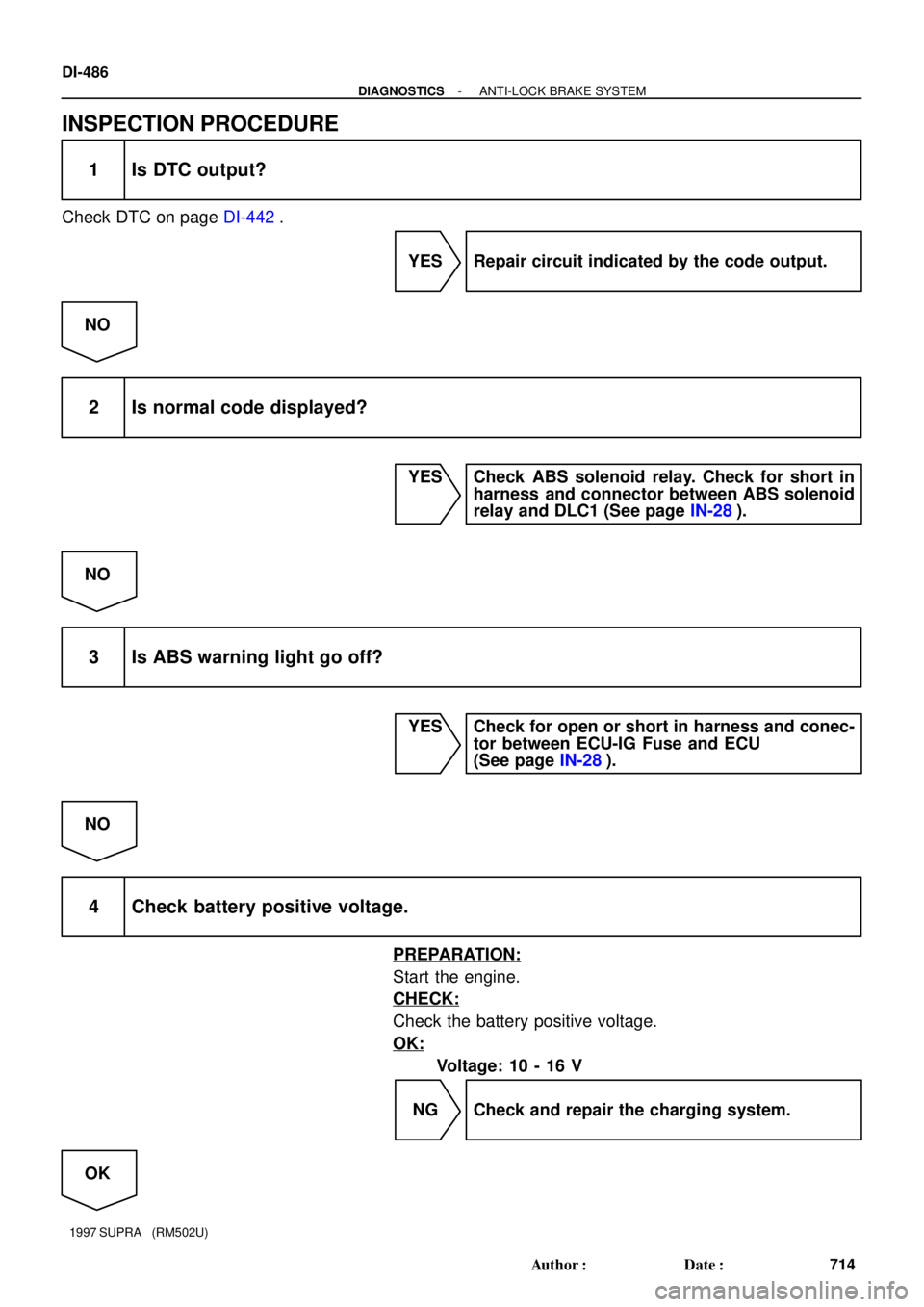
INSPECTION PROCEDURE
1 Is DTC output?
Check DTC on page DI-442.
YES Repair circuit indicated by the code output.
NO
2 Is normal code displayed?
YES Check ABS solenoid relay. Check for short in
harness and connector between ABS solenoid
relay and DLC1 (See page IN-28).
NO
3 Is ABS warning light go off?
YES Check for open or short in harness and conec-
tor between ECU-IG Fuse and ECU
(See page IN-28).
NO
4 Check battery positive voltage.
PREPARATION:
Start the engine.
CHECK:
Check the battery positive voltage.
OK:
Voltage: 10 - 16 V
NG Check and repair the charging system.
OK
Page 826 of 1807
F03368
Throttle Control
ECU R/B No.5
Throttle Control Relay
(TRAC Solenoid Relay)
R/B
No.2
Battery+B
RLY-
RLY+
E01 9
12
4
13
BR L-B BR-BL-R 14
11
12
L-B L-Y
TRAC
L-R
BR-B
B
2
12A2
15
4 3
51
65
5
T15
EC IB5 T16T16T16
IB5 IB5
- DIAGNOSTICSABS & TRACTION CONTROL SYSTEM
DI-535
763 Author�: Date�:
1997 SUPRA (RM502U)
DTC 51, 52 Power Source Circuit
CIRCUIT DESCRIPTION
DTC No.DTC Detecting ConditionTrouble Area
51In case power source voltage comes down, sub-throttle valve
angle difference occurs.�Wire harness and connector (+B and E01 circuit)
�Throttle control ECU
52Engine speed is 500 rpm or more and throttle relay is ON and
ECU terminal +B voltage is less than 8 V for 10 sec. or more.
�Battery
�IC regulator
�Wire harness and connector (+B and E01 circuit)
�Throttle control ECU
WIRING DIAGRAM
INSPECTION PROCEDURE
1 Check battery positive voltage.
OK:
Voltage: 10 - 14 V
NG Check and repair the charging system.
OK
DI4W5-01
Page 877 of 1807

(+)
DI-586
- DIAGNOSTICSSUPPLEMENTAL RESTRAINT SYSTEM
814 Author�: Date�:
1997 SUPRA (RM502U)
DTC 31 Airbag Sensor Assembly Malfunction
CIRCU")
AB0119
W02766H00041
ONAirbag Sensor Assembly
ACC
IG2 (-)
(+)
DI-586
- DIAGNOSTICSSUPPLEMENTAL RESTRAINT SYSTEM
814 Author�: Date�:
1997 SUPRA (RM502U)
DTC 31 Airbag Sensor Assembly Malfunction
CIRCUIT DESCRIPTION
The airbag sensor assembly consists of a airbag sensor, safing sensor, drive circuit, diagnosis circuit and
ignition control, etc.
It receives signals from the airbag sensors, judges whether or not the SRS must be activated, and diagnosis
system malfunction.
DTC 31 is recorded when occurrence of a malfunction in the airbag sensor assembly is detected.
DTC No.DTC Detecting ConditionTrouble Area
31�Airbag sensor assembly malfunction.�Airbag sensor assembly
INSPECTION PROCEDURES
HINT:
When a malfunction code other than code 31 is displayed at the same time, first repair the malfunction indi-
cated by the malfunction code other than code 31.
1 Preparation (See step 1 on page DI-595).
2 Check voltage at IG2 and ACC of airbag sensor assembly.
PREPARATION:
Turn the ignition switch ON.
CHECK:
Measure the voltage between terminals IG2 and ACC of airbag
sensor assembly and body ground.
OK:
Voltage: Below 16 V
NG Check battery and charging system.
(See charging system section)
OK
DI4WO-01


R/B
No.2
Battery+B
RLY-
RLY+
E01 9
12
4
13
BR L-B BR-BL-R 14
11
12
L-B L-Y
TRAC
L-R
BR-B
B
2
12A2
15
4 3
51
65
5
T15
E")