Page 1553 of 1807
CH03P-02
P10627
P10628
Socket
Wrench
P21010
SST
N00581
SST
P13567
- CHARGINGGENERATOR
CH-13
1536 Author�: Date�:
1997 SUPRA (RM502U)
REPLACEMENT
1. REPLACE FRONT BEARING
(a) Remove the 4 screws, bearing retainer and bearing.
(b) Using a socket wrench and press, press out the bearing.
(c) Using SST and a press, press in a new bearing.
SST 09950-60010 (09951-00500)
(d) Install the bearing retainer with the 4 screws.
Torque: 3.0 N´m (31 kgf´cm, 27 in.´lbf)
2. REPLACE REAR BEARING
(a) Using SST, remove the bearing cover (outside) and bear-
ing.
SST 09820-00021
NOTICE:
Be careful not to damage the fan.
(b) Remove the beating cover (inside).
(c) Place the bearing cover (inside) on the rotor.
Page 1554 of 1807
N00578
SST
P00074
SST
CH-14
- CHARGINGGENERATOR
1537 Author�: Date�:
1997 SUPRA (RM502U)
(d) Using SST and a press, press in a new bearing.
SST 09820-00030
(e) Using SST, push in the bearing cover (outside).
SST 09285-76010
Page 1555 of 1807

CH03Q-01
P10637
P10640
29 mm
Socket
Wrench
P10635
P10835
Turn
SST (A)
SST (B)
Z00045
SST (C)
- CHARGINGGENERATOR
CH-15
1538 Author�: Date�:
1997 SUPRA (RM502U)
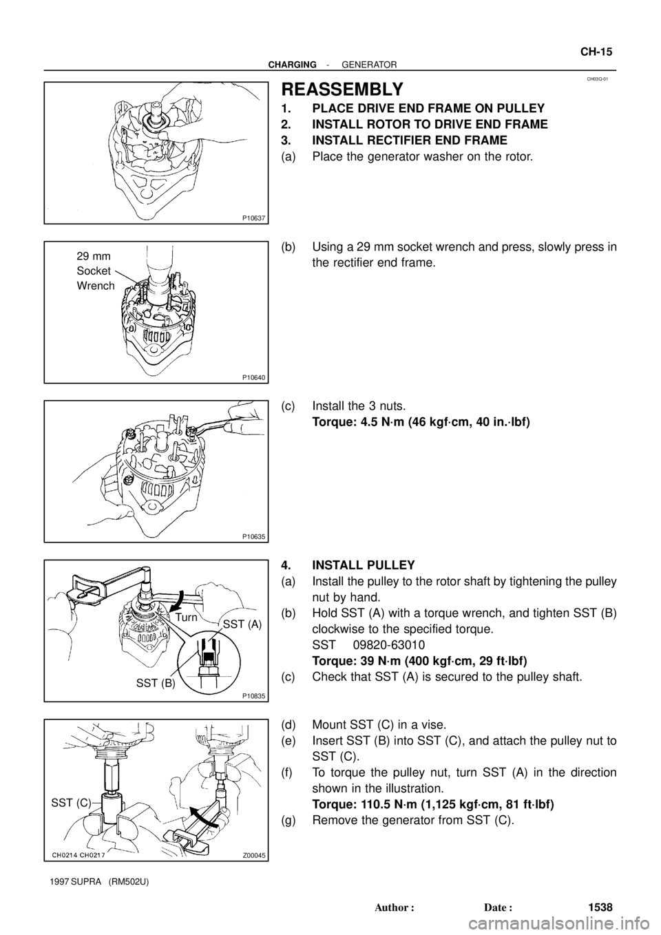
REASSEMBLY
1. PLACE DRIVE END FRAME ON PULLEY
2. INSTALL ROTOR TO DRIVE END FRAME
3. INSTALL RECTIFIER END FRAME
(a) Place the generator washer on the rotor.
(b) Using a 29 mm socket wrench and press, slowly press in
the rectifier end frame.
(c) Install the 3 nuts.
Torque: 4.5 N´m (46 kgf´cm, 40 in.´lbf)
4. INSTALL PULLEY
(a) Install the pulley to the rotor shaft by tightening the pulley
nut by hand.
(b) Hold SST (A) with a torque wrench, and tighten SST (B)
clockwise to the specified torque.
SST 09820-63010
Torque: 39 N´m (400 kgf´cm, 29 ft´lbf)
(c) Check that SST (A) is secured to the pulley shaft.
(d) Mount SST (C) in a vise.
(e) Insert SST (B) into SST (C), and attach the pulley nut to
SST (C).
(f) To torque the pulley nut, turn SST (A) in the direction
shown in the illustration.
Torque: 110.5 N´m (1,125 kgf´cm, 81 ft´lbf)
(g) Remove the generator from SST (C).
Page 1556 of 1807
P10836
SST (A)
SST (B)Turn
P10837
P10830
Push
P11842
P11839
CH-16
- CHARGINGGENERATOR
1539 Author�: Date�:
1997 SUPRA (RM502U)
(h) Turn SST (B), and remove SST (A and B).
5. INSTALL RECTIFIER HOLDER
(a) Install the 4 rubber insulators on the lead wires.
(b) Install the rectifier holder while pushing it with the 4
screws.
Torque: 2.9 N´m (30 kgf´cm, 26 in.´lbf)
6. INSTALL WIRE CLIP
Install the wire clip with the nut.
Torque: 5.4 N´m (55 kgf´cm, 48 in.´lbf)
7. INSTALL VOLTAGE REGULATOR AND BRUSH
HOLDER
(a) Place the seal plate on the rectifier end frame.
Page 1557 of 1807
S05216
Upward
P11840
Brush Holder Cover
P11838
Plate Terminal
- CHARGINGGENERATOR
CH-17
1540 Author�: Date�:
1997 SUPRA (RM502U)
(b) Place the voltage regulator and brush holder on the recti-
fier end frame.
NOTICE:
Be careful of the holder installation direction.
(c) Install the 5 screws.
Torque: 2.0 N´m (20 kgf´cm, 18 in.´lbf)
(d) Place the brush holder cover on the brush holder.
8. INSTALL REAR END COVER
(a) Install the end cover and plate terminal with the bolt and
3 nuts.
Torque:
Nut 4.4 N´m (45 kgf´cm, 39 in.´lbf)
Bolt 3.9 N´m (40 kgf´cm, 35 in.´lbf)
(b) Install the terminal insulator with the nut.
Torque: 6.5 N´m (67 kgf´cm, 58 in.´lbf)
9. CHECK THAT ROTOR ROTATES SMOOTHLY
Page 1737 of 1807
SS0DO-02
SS-14
- SERVICE SPECIFICATIONSTURBOCHARGING (2JZ-GTE)
171 Author�: Date�:
1997 SUPRA (RM502U)
TURBOCHARGING (2JZ-GTE)
SERVICE DATA
TurbochargerTurbocharging pressure
Impeller wheel axial playMaximum
Impeller wheel radial playMaximum61 - 75 kPa (0.62 - 0.76 kgf/cm2, 8.8 - 10.8 psi)
0.162 mm (0.0064 in.)
0.110 mm (0.0045 in.)
Page 1738 of 1807

SS0DP-02
- SERVICE SPECIFICATIONSTURBOCHARGING (2JZ-GTE)
SS-15
172 Author�: Date�:
1997 SUPRA (RM502U)
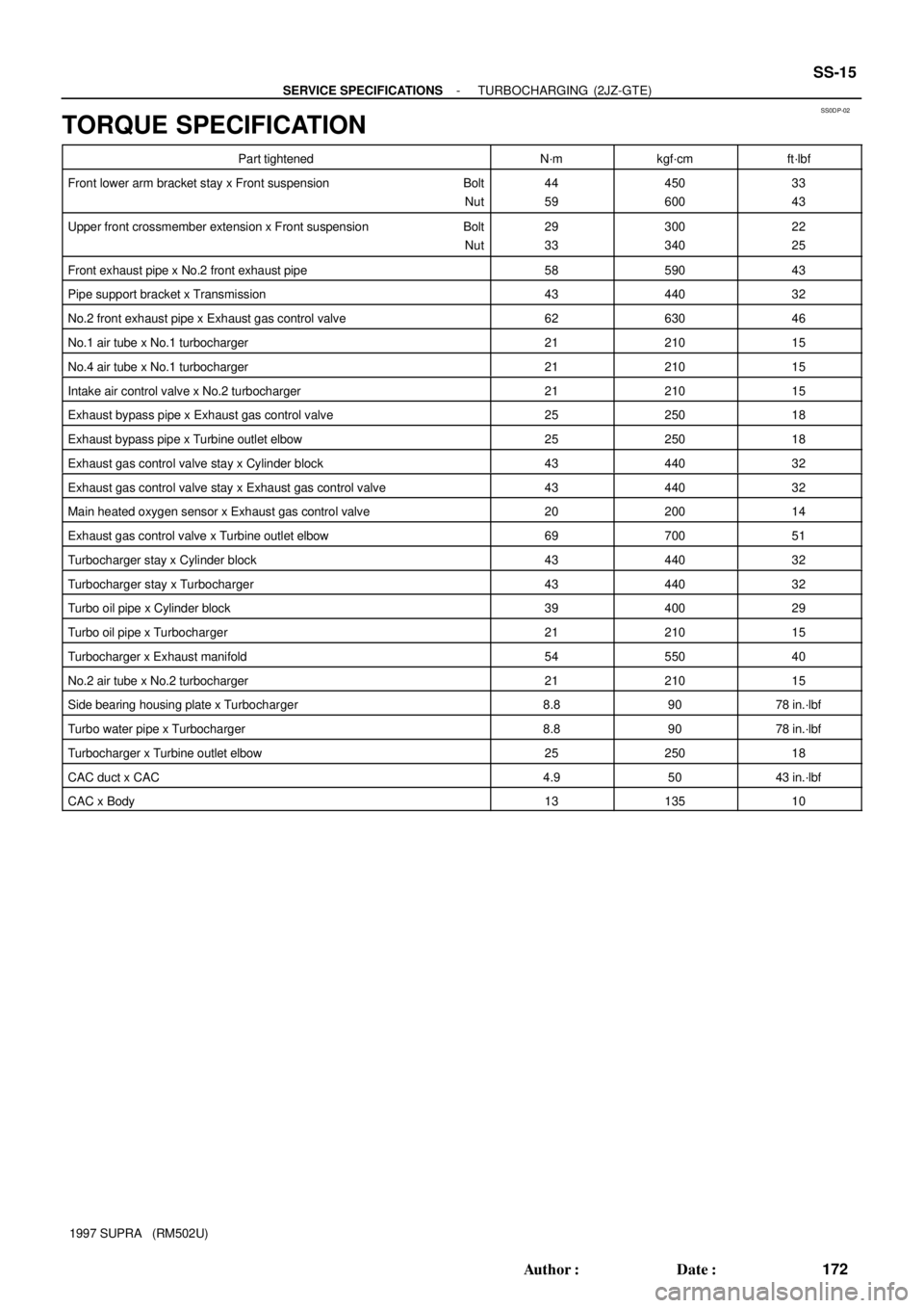
TORQUE SPECIFICATION
Part tightenedN´mkgf´cmft´lbf
Front lower arm bracket stay x Front suspension Bolt
Nut44
59450
60033
43
Upper front crossmember extension x Front suspension Bolt
Nut29
33300
34022
25
Front exhaust pipe x No.2 front exhaust pipe5859043
Pipe support bracket x Transmission4344032
No.2 front exhaust pipe x Exhaust gas control valve6263046
No.1 air tube x No.1 turbocharger2121015
No.4 air tube x No.1 turbocharger2121015
Intake air control valve x No.2 turbocharger2121015
Exhaust bypass pipe x Exhaust gas control valve2525018
Exhaust bypass pipe x Turbine outlet elbow2525018
Exhaust gas control valve stay x Cylinder block4344032
Exhaust gas control valve stay x Exhaust gas control valve4344032
Main heated oxygen sensor x Exhaust gas control valve2020014
Exhaust gas control valve x Turbine outlet elbow6970051
Turbocharger stay x Cylinder block4344032
Turbocharger stay x Turbocharger4344032
Turbo oil pipe x Cylinder block3940029
Turbo oil pipe x Turbocharger2121015
Turbocharger x Exhaust manifold5455040
No.2 air tube x No.2 turbocharger2121015
Side bearing housing plate x Turbocharger8.89078 in.´lbf
Turbo water pipe x Turbocharger8.89078 in.´lbf
Turbocharger x Turbine outlet elbow2525018
CAC duct x CAC4.95043 in.´lbf
CAC x Body1313510
Page 1751 of 1807
SS0E6-01
- SERVICE SPECIFICATIONSCHARGING
SS-33
190 Author�: Date�:
1997 SUPRA (RM502U)
CHARGING
SERVICE DATA
BatteryVoltage (Maintenance-free battery) at 20°C (68°F)
Specific gravity (Except maintenance-free battery)
at 20°C (68°F)12.5 - 12.9 V
1.25 - 1.29
GeneratorRated output2JZ-GE
2JZ-GTE (M/T)
2JZ-GTE (A/T)
Rotor coil resistance at 20°C (68°C)
Slip ring diameter STD
Minimum
Brush exposed length STD
Minimum12 V 80 A
12 V 90 A
12 V 100 A
2.7 - 3.1 W
14.2 - 14.4 mm (0.559 - 0.567 in.)
12.8 mm (0.504 in.)
9.5 -11.5 mm (0.374 -0.453 in.)
1.5 mm (0.059 in.)
Voltage regulatorRegulating voltage13.2 - 14.8 V