Page 2 of 1807

CL-2
- CLUTCHTROUBLESHOOTING
1543 Author�: Date�:
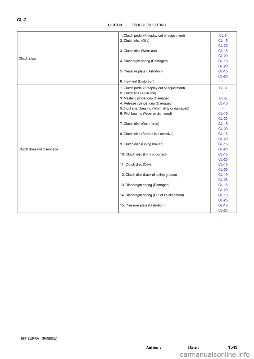
1997 SUPRA (RM502U) Clutch slips
1. Clutch pedal (Freeplay out of adjustment)
2. Clutch disc (Oily)
3. Clutch disc (Worn out)
4. Diaphragm spring (Damaged)
5. Pressure plate (Distortion)
6. Flywheel (Distortion)CL-3
CL-15
CL-20
CL-15
CL-20
CL-15
CL-20
CL-15
CL-20
-
Clutch does not disengage
1. Clutch pedal (Freeplay out of adjustment)
2. Clutch line (Air in line)
3. Master cylinder cup (Damaged)
4. Release cylinder cup (Damaged)
5. Input shaft bearing (Worn, dirty or damaged)
6. Pilot bearing (Worn or damaged)
7. Clutch disc (Out of true)
8. Clutch disc (Runout is excessive)
9. Clutch disc (Lining broken)
10. Clutch disc (Dirty or burred)
11. Clutch disc (Oily)
12. Clutch disc (Lack of spline grease)
13. Diaphragm spring (Damaged)
14. Diaphragm spring (Out of tip alignment)
15. Pressure plate (Distortion)CL-3
-
CL-5
CL-10
-
CL-15
CL-20
CL-15
CL-20
CL-15
CL-20
CL-15
CL-20
CL-15
CL-20
CL-15
CL-20
CL-19
CL-25
CL-15
CL-20
CL-19
CL-25
CL-15
CL-20
Page 7 of 1807
CL04A-03
Q06260
Plate Washer
Wave Washer
� Snap Ring
Clutch Thrust Cone Spring
Clutch Release Hub
Release Fork Support Clutch DiscClutch Release BearingPlate Washer
Release Fork Support Spring
� E-Ring
Release Fork x9
� Pilot BearingClutch Cover
� Snap Ring
Wave
Washer Flywheel
Assembly
25 (260, 18)
19 (195, 14)
See page CL-22
N´m (kgf´cm, ft´lbf): Specified torque
� Non-reusable part
Pin � CL-20
- CLUTCHCLUTCH UNIT (2JZ-GTE)
1561 Author�: Date�:
1997 SUPRA (RM502U)
CLUTCH UNIT (2JZ-GTE)
COMPONENTS
Page 9 of 1807
CL04C-02
Q04200
Q04201
Q04202
Q04204
Q04206
CL-22
- CLUTCHCLUTCH UNIT (2JZ-GTE)
1563 Author�: Date�:
1997 SUPRA (RM502U)
INSPECTION
1. INSPECT CLUTCH DISC FOR WEAR OR DAMAGE
Using calipers, measure the rivet head depth.
Maximum rivet depth: 0.3 mm (0.012 in.)
If necessary, replace the clutch disc.
2. INSPECT CLUTCH DISC RUNOUT
Using a dial indicator, check the disc runout.
Maximum runout: 0.8 mm (0.031 in.)
If the runout is excessive, replace the clutch disc.
3. INSPECT FLYWHEEL RUNOUT
Using a dial indicator, check the flywheel runout.
Maximum runout: 0.1 mm (0.004 in.)
If the runout is excessive, replace the flywheel.
4. INSPECT PILOT BEARING
Turn the bearing by hand while applying force in the axial direc-
tion.
If the bearing sticks or has much resistance, replace the pilot
bearing.
5. IF NECESSARY, REPLACE PILOT BEARING
(a) Remove the 2 bolts at the diametrically opposite points.
Page 11 of 1807

Q04326
Matchmarks
Secondary
FlywheelPrimary
Flywheel
Q04327
Matchmarks CL-24
- CLUTCHCLUTCH UNIT (2JZ-GTE)
1565 Author�: Date�:
1997 SUPRA (RM502U)
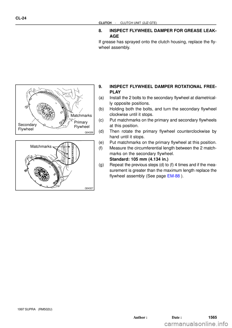
8. INSPECT FLYWHEEL DAMPER FOR GREASE LEAK-
AGE
If grease has sprayed onto the clutch housing, replace the fly-
wheel assembly.
9. INSPECT FLYWHEEL DAMPER ROTATIONAL FREE-
PLAY
(a) Install the 2 bolts to the secondary flywheel at diametrical-
ly opposite positions.
(b) Holding both the bolts, and turn the secondary flywheel
clockwise until it stops.
(c) Put matchmarks on the primary and secondary flywheels
at this position.
(d) Then rotate the primary flywheel counterclockwise by
hand until it stops.
(e) Put matchmarks on the primary flywheel at this position.
(f) Measure the circumferential length between the 2 match-
marks on the secondary flywheel.
Standard: 105 mm (4.134 in.)
(g) Repeat the previous steps (d) to (f) 4 times and if the mea-
surement is greater than the maximum length replace the
flywheel assembly (See page EM-88).
Page 12 of 1807

CL04D-01
Z13786
SST Front
Q04210
SST 7
3
1, 4
2, 58 6 Matchmarks
Q06263
SST
Q04219
Q04403
- CLUTCHCLUTCH UNIT (2JZ-GTE)
CL-25
1566 Author�: Date�:
1997 SUPRA (RM502U)
INSTALLATION
1. INSTALL CLUTCH DISC AND COVER ON FLYWHEEL
(a) Insert SST in the clutch disc, then set them and the cover
in position.
SST 09301-001 10
(b) Align the matchmarks on the clutch cover and flywheel.
(c) Tighten the bolts evenly and gradually while pushing the
SST. Make several passes around the cover until it is
snug.
(d) Torque the bolts on the clutch cover in the order shown.
Torque: 19 N´m (195 kgf´cm, 14 ft´lbf)
HINT:
Temporarily tighten the No.1 and No.2 bolts.
2. CHECK DIAPHRAGM SPRING TIP ALIGNMENT
Using a dial indicator with roller instrument, check the dia-
phragm spring tip alignment.
Maximum non-alignment: 0.5 mm (0.020 in.)
If the alignment is not as specified, use SST to adjust the dia-
phragm spring tip alignment.
SST 09333-00013
3. REMOVE CLUTCH COVER AND CLUTCH DISC
4. INSTALL CLUTCH RELEASE FORK
(a) Install the wave washer and pin to release fork.
(b) Install a new E-ring.
5. APPLY MOLYBDENUM DISULPHIDE LITHIUM BASE
GREASE (NLGI NO.2)
(a) Apply release hub grease to these parts:
�Release fork and hub contact point
�Release fork and push rod contact point
�Release fork pivot point
Page 15 of 1807

Q04160
Push Rod Play and
Freeplay Adjust Point
Pedal
HeightPedal Height
Adjust Point
Push Rod PlayCL03Z-01
CL0102Pedal Freeplay
Z13785
25 mm (0.98 in.) or more
Full Pedal Stroke Full Stroke
End PositionRelease
Point
- CLUTCHCLUTCH PEDAL
CL-3
1544 Author�: Date�:
1997 SUPRA (RM502U)
CLUTCH PEDAL
INSPECTION
1. CHECK PEDAL HEIGHT
Pedal height from asphalt sheet:
146.2 - 156.2 mm (5.76 - 6.15 in.)
2. IF NECESSARY, ADJUST PEDAL HEIGHT
Loosen the lock nut and clutch switch until the height is correct.
Tighten the lock nut.
HINT:
Before rotating the clutch switch for pedal height adjustment,
disconnect the clutch switch connector.
3. CHECK PEDAL FREEPLAY AND PUSH ROD PLAY
Push in on the pedal until the beginning of clutch resistance is
felt.
Pedal freeplay: 5.0 - 15.0 mm (0.197 - 0.591 in.)
Gently push on the pedal until the resistance begins to increase
a little.
Push rod play at pedal top:
1.0 - 5.0 mm (0.039 - 0.197 in.)
4. IF NECESSARY, ADJUST PEDAL FREEPLAY AND
PUSH ROD PLAY
(a) Loosen the lock nut and turn the push rod until the free-
play and push rod play are correct.
(b) Tighten the lock nut.
(c) After adjusting the pedal freeplay, check the pedal height.
5. INSPECT FULL PEDAL STROKE
Full pedal stroke: 132.0 - 138.0 mm (5.20 - 5.43 in.)
6. INSPECT CLUTCH RELEASE POINT
(a) Pull the parking brake lever and install wheel stopper.
(b) Start the engine and idle the engine.
(c) Without depressing the clutch pedal, slowly shift the shift
lever into the reverse position until the gears contact.
(d) Gradually depress the clutch pedal and measure the
stroke distance from the point the gear noise stops (re-
lease point) up to the full stroke end position.
Page 21 of 1807
MT06M-02
- MANUAL TRANSMISSION (V160)TROUBLESHOOTING
MT-1
1569 Author�: Date�:
1997 SUPRA (RM502U)
TROUBLESHOOTING
PROBLEM SYMPTOMS TABLE
Use the table below to help you find the cause of the problem. The numbers indicate the priority of the likely
cause of the problem. Check each part in order. If necessary, replace these parts.
SymptomSuspect AreaSee page
Noise
1. Flywheel damper
2. Oil (Level low)
3. Oil (Wrong)
4. Gear (Worn or damaged)
5. Bearing (Worn or damaged)CL-17
CL-22
MT-3
MT-3
-
-
Oil leakage
1. Oil (Level too high)
2. Gasket (Damaged)
3. Oil seal (Worn or damaged)
4. O-Ring (Worn or damaged)MT-3
-
MT-7
MT-2
MT-7
Hard to shift or will not shift1. Synchronizer ring (Worn or damaged)
2. Shift key spring (Damaged)-
-
Jumps out of gear
1. Locking ball spring (Damaged)
2. Shift fork (Worn)
3. Gear (Worn or damaged)
4. Bearing (Worn or damaged)-
-
-
-
Page 25 of 1807

Q04136Matchmarks
Q04137
Q04138
Q04341
Q04141
A
B
A
- MANUAL TRANSMISSION (V160)MANUAL TRANSMISSION UNIT
MT-5
1573 Author�: Date�:
1997 SUPRA (RM502U)
15. REMOVE CLUTCH COVER SET BOLT
(a) Remove the 2 bolts and service hole cover.
Torque: 12 N´m (120 kgf´cm, 9 ft´lbf)
(b) Place matchmarks on the flywheel and clutch cover.
(c) Remove the 6 bolts.
Torque: 19 N´m (195 kgf´cm, 14 ft´lbf)
16. JACK UP TRANSMISSION SLIGHTLY
Using a transmission jack, support the transmission.
17. REMOVE REAR ENGINE MOUNTING MEMBER
Remove the 4 nuts, bolts and rear engine mounting member.
Torque:
Nut: 13 N´m (135 kgf´cm, 10 ft´lbf)
Bolt: 25 N´m (260 kgf´cm, 19 ft´lbf)
18. REMOVE STARTER
Lower the engine rear side and remove the 2 bolts and starter.
Torque: 39 N´m (400 kgf´cm, 29 ft´lbf)
19. REMOVE TRANSMISSION
Remove the 5 transmission mounting bolts and transmission
from the engine.
Torque: 72 N´m (730 kgf´cm, 53 ft´lbf)
20. REMOVE SHIFT LEVER RETAINER
Remove the 5 bolts, nut and shift lever retainer from the trans-
mission.
Torque:
Bolt A: 19 N´m (195 kgf´cm, 14 ft´lbf)
Nut B: 25 N´m (250 kgf´cm, 18 ft´lbf)
21. REMOVE ENGINE REAR MOUNTING
Remove the 4 bolts and engine rear mounting from the trans-
mission.
Torque: 25 N´m (250 kgf´cm, 18 ft´lbf)