Page 149 of 1807
AC0RC-01
N08535
N08693
N08540
- AIR CONDITIONINGSENSOR
AC-69
2217 Author�: Date�:
1997 SUPRA (RM502U)
SENSOR
REMOVAL
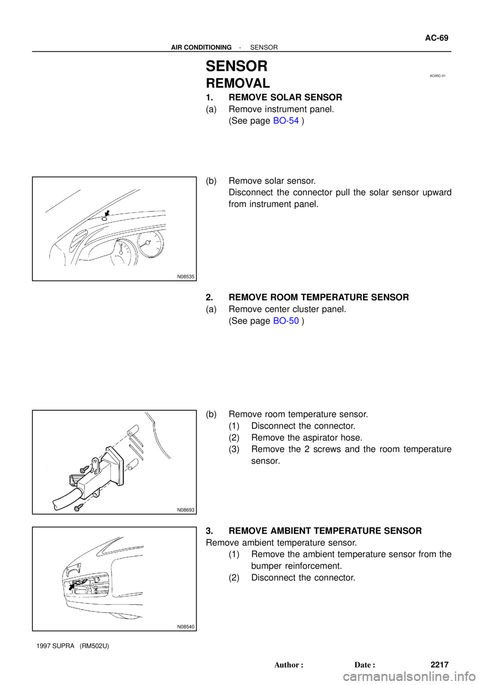
1. REMOVE SOLAR SENSOR
(a) Remove instrument panel.
(See page BO-54)
(b) Remove solar sensor.
Disconnect the connector pull the solar sensor upward
from instrument panel.
2. REMOVE ROOM TEMPERATURE SENSOR
(a) Remove center cluster panel.
(See page BO-50)
(b) Remove room temperature sensor.
(1) Disconnect the connector.
(2) Remove the aspirator hose.
(3) Remove the 2 screws and the room temperature
sensor.
3. REMOVE AMBIENT TEMPERATURE SENSOR
Remove ambient temperature sensor.
(1) Remove the ambient temperature sensor from the
bumper reinforcement.
(2) Disconnect the connector.
Page 307 of 1807
N19395
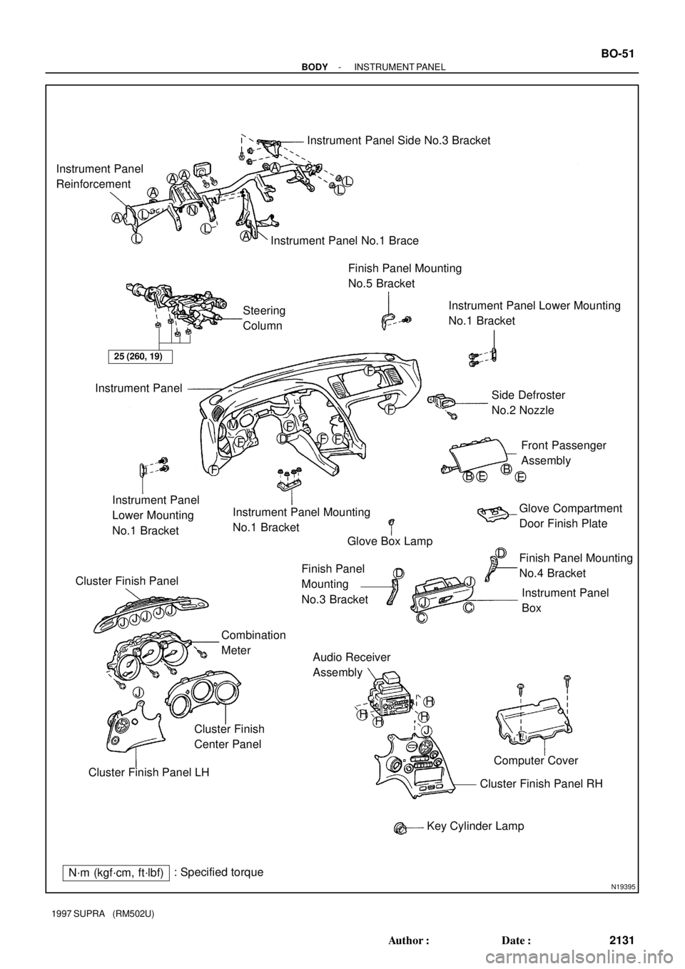
Instrument Panel Side No.3 Bracket
Instrument Panel
Reinforcement
AAAA
A N
LL
LLL A
Instrument Panel No.1 Brace
Steering
ColumnFinish Panel Mounting
No.5 Bracket
Instrument Panel Lower Mounting
No.1 Bracket
Instrument Panel
Side Defroster
No.2 Nozzle
Front Passenger
Assembly M
D
FF
FF
F
F
Instrument Panel Mounting
No.1 Bracket Instrument Panel
Lower Mounting
No.1 Bracket
Glove Box LampB
E B
E
Glove Compartment
Door Finish Plate
Instrument Panel
Box Finish Panel Mounting
No.4 Bracket Finish Panel
Mounting
No.3 BracketD
J
CJ
CD
Cluster Finish Panel
JJJJJ
Combination
Meter
Audio Receiver
Assembly
Cluster Finish
Center Panel
Cluster Finish Panel LHComputer Cover
Cluster Finish Panel RH
Key Cylinder Lamp H
J HH
H JF
25 (260, 19)
N´m (kgf´cm, ft´lbf): Specified torque
- BODYINSTRUMENT PANEL
BO-51
2131 Author�: Date�:
1997 SUPRA (RM502U)
Page 310 of 1807
BO0RB-01
N08458
: 5 Clips
N087123 Clips
N117963 Clips
N08460
BO-54
- BODYINSTRUMENT PANEL
2134 Author�: Date�:
1997 SUPRA (RM502U)
REMOVAL
1. REMOVE STEERING WHEEL
(See page SR-1 1)
CAUTION:
�When storing the wheel pad, keep the upper surface
of the pad facing upward.
�Never disassemble the steering wheel pad.
2. REMOVE THESE PARTS:
HINT:
Tape a screwdriver tip before use.
(a) Front pillar garnishes
(b) Assist grip
(c) Foot rest
(d) Front door scuff inside plates
(e) Steering column cover
(f) Console upper panel
(g) Parking brake hole cover
(h) Console box
(i) Finish panel
(j) Finish lower LH panel
(k) Cluster finish panel
Page 311 of 1807
N084614 Clips
N084624 Clips
N162798 Clips
R06995
N084641 Clip
- BODYINSTRUMENT PANEL
BO-55
2135 Author�: Date�:
1997 SUPRA (RM502U)
(l) Cluster finish center panel
(m) Cluster finish panel LH
(n) Cluster finish panel RH
(o) Combination meter
(p) Heater to register No.2 duct
(q) Combination switch
(r) Audio receiver assembly
(s) Computer cover
3. REMOVE INSTRUMENT PANEL BOX
(a) Remove the glove compartment door finish plate inside
the instrument panel box.
NOTICE:
When handling the airbag connector, take care not to dam-
age the airbag wire harness.
(b) Pull up and disconnect the airbag connector.
(c) Remove the instrument panel box.
4. REMOVE THESE PARTS:
(a) Finish panel mounting No.3 and No.4 brackets
(b) Heater to register No.4 duct
(c) Finish panel mounting No.5 bracket
Page 909 of 1807
I02538
10 (+)9 (-)
DI-618
- DIAGNOSTICSTHEFT DETERRENT SYSTEM
846 Author�: Date�:
1997 SUPRA (RM502U)
INSPECTION PROCEDURE
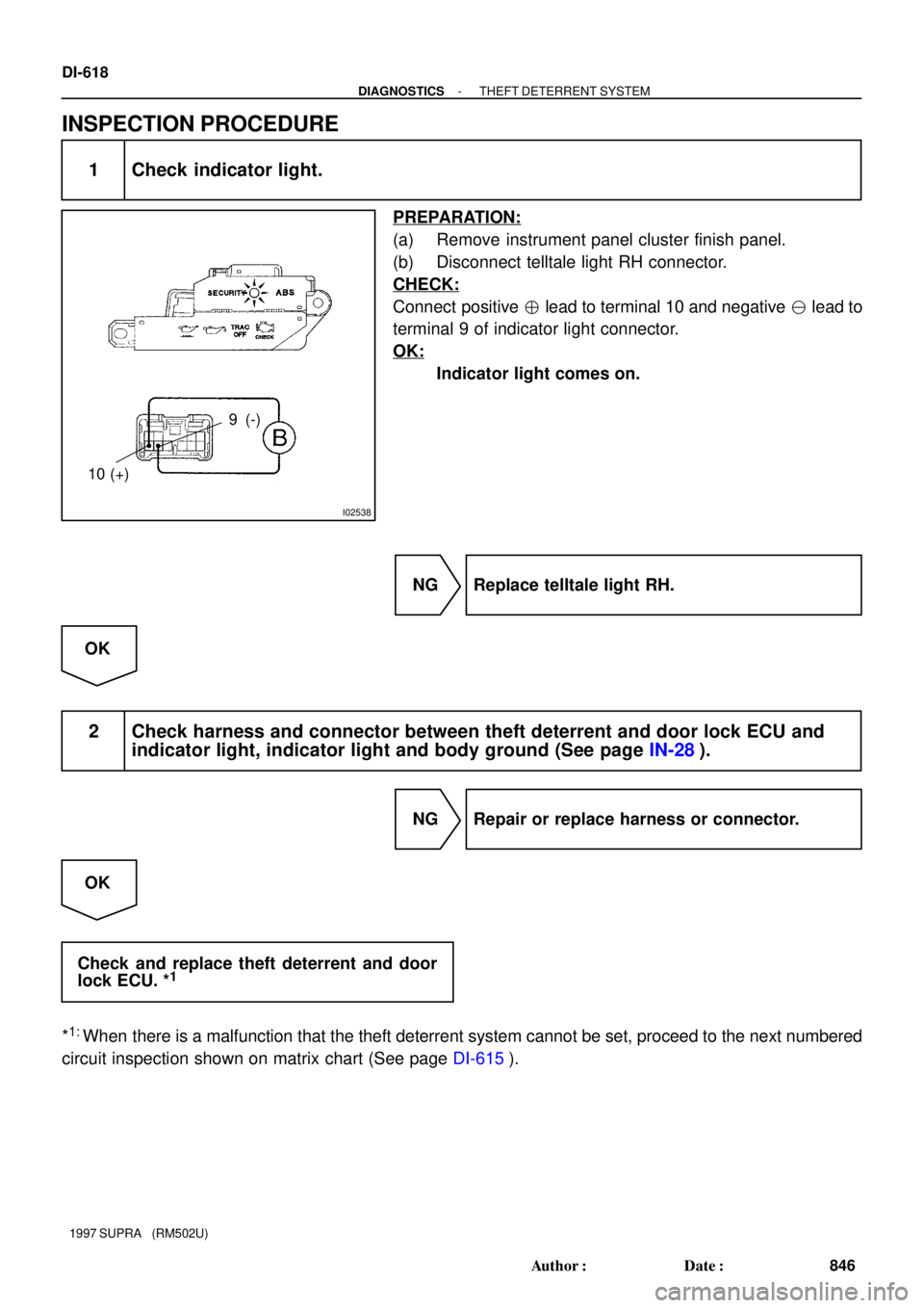
1 Check indicator light.
PREPARATION:
(a) Remove instrument panel cluster finish panel.
(b) Disconnect telltale light RH connector.
CHECK:
Connect positive � lead to terminal 10 and negative � lead to
terminal 9 of indicator light connector.
OK:
Indicator light comes on.
NG Replace telltale light RH.
OK
2 Check harness and connector between theft deterrent and door lock ECU and
indicator light, indicator light and body ground (See page IN-28).
NG Repair or replace harness or connector.
OK
Check and replace theft deterrent and door
lock ECU. *
1
*1:
When there is a malfunction that the theft deterrent system cannot be set, proceed to the next numbered
circuit inspection shown on matrix chart (See page DI-615).