Page 2 of 1807
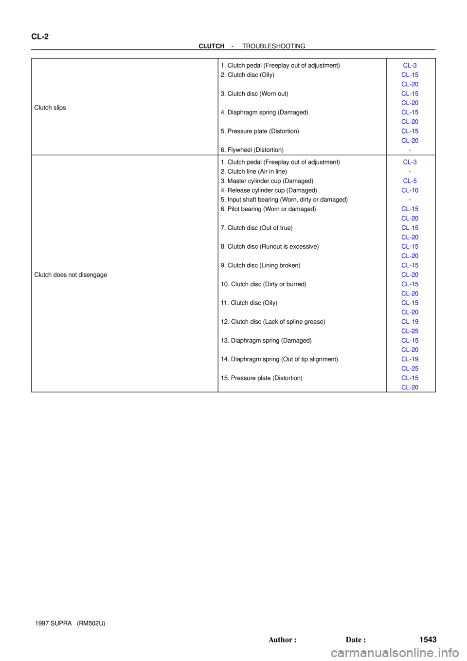
CL-2
- CLUTCHTROUBLESHOOTING
1543 Author�: Date�:
1997 SUPRA (RM502U) Clutch slips
1. Clutch pedal (Freeplay out of adjustment)
2. Clutch disc (Oily)
3. Clutch disc (Worn out)
4. Diaphragm spring (Damaged)
5. Pressure plate (Distortion)
6. Flywheel (Distortion)CL-3
CL-15
CL-20
CL-15
CL-20
CL-15
CL-20
CL-15
CL-20
-
Clutch does not disengage
1. Clutch pedal (Freeplay out of adjustment)
2. Clutch line (Air in line)
3. Master cylinder cup (Damaged)
4. Release cylinder cup (Damaged)
5. Input shaft bearing (Worn, dirty or damaged)
6. Pilot bearing (Worn or damaged)
7. Clutch disc (Out of true)
8. Clutch disc (Runout is excessive)
9. Clutch disc (Lining broken)
10. Clutch disc (Dirty or burred)
11. Clutch disc (Oily)
12. Clutch disc (Lack of spline grease)
13. Diaphragm spring (Damaged)
14. Diaphragm spring (Out of tip alignment)
15. Pressure plate (Distortion)CL-3
-
CL-5
CL-10
-
CL-15
CL-20
CL-15
CL-20
CL-15
CL-20
CL-15
CL-20
CL-15
CL-20
CL-15
CL-20
CL-19
CL-25
CL-15
CL-20
CL-19
CL-25
CL-15
CL-20
Page 12 of 1807

CL04D-01
Z13786
SST Front
Q04210
SST 7
3
1, 4
2, 58 6 Matchmarks
Q06263
SST
Q04219
Q04403
- CLUTCHCLUTCH UNIT (2JZ-GTE)
CL-25
1566 Author�: Date�:
1997 SUPRA (RM502U)
INSTALLATION
1. INSTALL CLUTCH DISC AND COVER ON FLYWHEEL
(a) Insert SST in the clutch disc, then set them and the cover
in position.
SST 09301-001 10
(b) Align the matchmarks on the clutch cover and flywheel.
(c) Tighten the bolts evenly and gradually while pushing the
SST. Make several passes around the cover until it is
snug.
(d) Torque the bolts on the clutch cover in the order shown.
Torque: 19 N´m (195 kgf´cm, 14 ft´lbf)
HINT:
Temporarily tighten the No.1 and No.2 bolts.
2. CHECK DIAPHRAGM SPRING TIP ALIGNMENT
Using a dial indicator with roller instrument, check the dia-
phragm spring tip alignment.
Maximum non-alignment: 0.5 mm (0.020 in.)
If the alignment is not as specified, use SST to adjust the dia-
phragm spring tip alignment.
SST 09333-00013
3. REMOVE CLUTCH COVER AND CLUTCH DISC
4. INSTALL CLUTCH RELEASE FORK
(a) Install the wave washer and pin to release fork.
(b) Install a new E-ring.
5. APPLY MOLYBDENUM DISULPHIDE LITHIUM BASE
GREASE (NLGI NO.2)
(a) Apply release hub grease to these parts:
�Release fork and hub contact point
�Release fork and push rod contact point
�Release fork pivot point
Page 376 of 1807
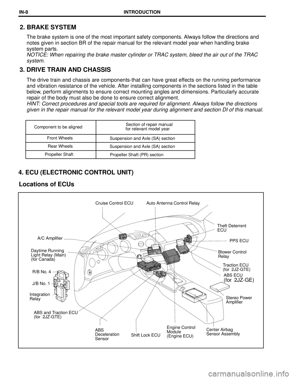
Shift Lock ECUEngine Control
Module
(Engine ECU)Center Airbag
Sensor Assembly ABS
Deceleration
Sensor ABS and Traction ECU
(for 2JZ-GTE)Stereo Power
Amplifier Integration
RelayJ/B No. 1Traction ECU
(for 2JZ-GTE)
R/B No. 4 Daytime Running
Light Relay (Main)
(for Canada)Blower Control
RelayPPS ECU A/C AmplifierTheft Deterrent
ECU Cruise Control ECU Auto Antenna Control Relay
ABS ECU
(for 2JZ-GE)
Component to be alignedSection of repair manual
for relevant model year
Front Wheels
Suspension and Axle (SA) section
Rear Wheels
Suspension and Axle (SA) section
Propeller Shaft
Propeller Shaft (PR) section
3. DRIVE TRAIN AND CHASSIS2. BRAKE SYSTEM
The brake system is one of the most important safety components. Always follow the directions and
notes given in section BR of the repair manual for the relevant model year when handling brake
system parts.
NOTICE: When repairing the brake master cylinder or TRAC system, bleed the air out of the TRAC
system.
The drive train and chassis are components-that can have great effects on the running performance
and vibration resistance of the vehicle. After installing components in the sections listed in the table
below, perform alignments to ensure correct mounting angles and dimensions. Particularly accurate
repair of the body must also be done to ensure correct alignment.
HINT: Correct procedures and special tools are required for alignment. Always follow the directions
given in the repair manual for the relevant model year during alignment and section DI of this manual.
4. ECU (ELECTRONIC CONTROL UNIT)
Locations of ECUs
INTRODUCTIONIN-8
Page 411 of 1807
mm in.
15 0.59 Assembly Mark
INSTALLATION
Tack Weld (15 mm each)
3. Temporarily install the front fender and hood,
and check the fit. 1. When temporarily installing the new parts,
determine the installation position by the
assembly mark.
2. Measurements must be accurate with the
body dimension diagram, as this affects the
front wheel alignment.
BODY PANEL REPLACEMENTRE-11
Page 414 of 1807
INSTALLATION
Front Side Member
Front Side Member No. 3
Reinforcement
Front Side Member
Plate
2. Temporarily install the new parts and mea-
sure each part in accordance with the body
dimension diagram.
HINT: Make sure each measurement is correct,
as this part affects the front wheel alignment.
1. Before temporarily installing the new front
side member, weld the front side member No.
3 reinforcement with standard points.
BODY PANEL REPLACEMENTRE-18
Page 1571 of 1807
SR13T-01
SR-2
- STEERINGTROUBLESHOOTING
1886 Author�: Date�:
1997 SUPRA (RM502U)
TROUBLESHOOTING
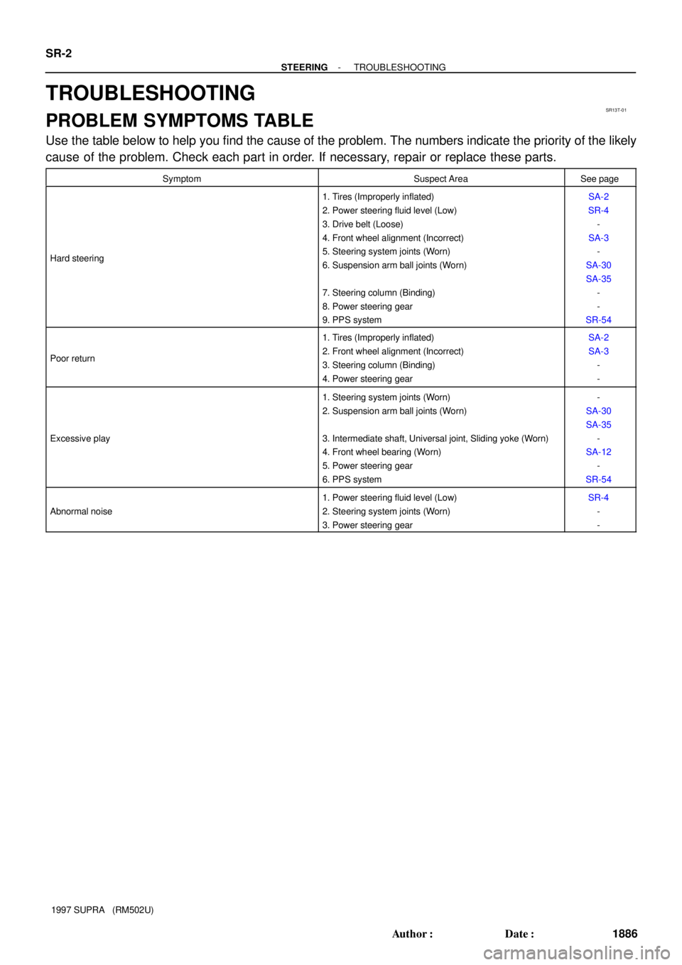
PROBLEM SYMPTOMS TABLE
Use the table below to help you find the cause of the problem. The numbers indicate the priority of the likely
cause of the problem. Check each part in order. If necessary, repair or replace these parts.
SymptomSuspect AreaSee page
Hard steering
1. Tires (Improperly inflated)
2. Power steering fluid level (Low)
3. Drive belt (Loose)
4. Front wheel alignment (Incorrect)
5. Steering system joints (Worn)
6. Suspension arm ball joints (Worn)
7. Steering column (Binding)
8. Power steering gear
9. PPS systemSA-2
SR-4
-
SA-3
-
SA-30
SA-35
-
-
SR-54
Poor return
1. Tires (Improperly inflated)
2. Front wheel alignment (Incorrect)
3. Steering column (Binding)
4. Power steering gearSA-2
SA-3
-
-
Excessive play
1. Steering system joints (Worn)
2. Suspension arm ball joints (Worn)
3. Intermediate shaft, Universal joint, Sliding yoke (Worn)
4. Front wheel bearing (Worn)
5. Power steering gear
6. PPS system-
SA-30
SA-35
-
SA-12
-
SR-54
Abnormal noise
1. Power steering fluid level (Low)
2. Steering system joints (Worn)
3. Power steering gearSR-4
-
-
Page 1621 of 1807
SR14E-01
SR-52
- STEERINGPOWER STEERING GEAR
1936 Author�: Date�:
1997 SUPRA (RM502U)
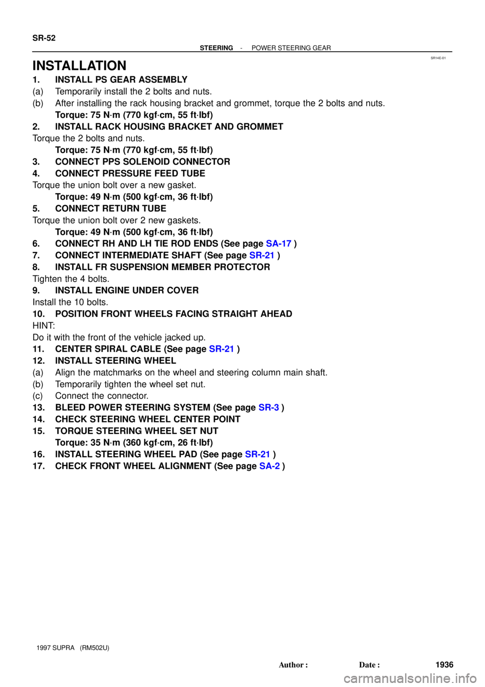
INSTALLATION
1. INSTALL PS GEAR ASSEMBLY
(a) Temporarily install the 2 bolts and nuts.
(b) After installing the rack housing bracket and grommet, torque the 2 bolts and nuts.
Torque: 75 N´m (770 kgf´cm, 55 ft´lbf)
2. INSTALL RACK HOUSING BRACKET AND GROMMET
Torque the 2 bolts and nuts.
Torque: 75 N´m (770 kgf´cm, 55 ft´lbf)
3. CONNECT PPS SOLENOID CONNECTOR
4. CONNECT PRESSURE FEED TUBE
Torque the union bolt over a new gasket.
Torque: 49 N´m (500 kgf´cm, 36 ft´lbf)
5. CONNECT RETURN TUBE
Torque the union bolt over 2 new gaskets.
Torque: 49 N´m (500 kgf´cm, 36 ft´lbf)
6. CONNECT RH AND LH TIE ROD ENDS (See page SA-17)
7. CONNECT INTERMEDIATE SHAFT (See page SR-21)
8. INSTALL FR SUSPENSION MEMBER PROTECTOR
Tighten the 4 bolts.
9. INSTALL ENGINE UNDER COVER
Install the 10 bolts.
10. POSITION FRONT WHEELS FACING STRAIGHT AHEAD
HINT:
Do it with the front of the vehicle jacked up.
11. CENTER SPIRAL CABLE (See page SR-21)
12. INSTALL STEERING WHEEL
(a) Align the matchmarks on the wheel and steering column main shaft.
(b) Temporarily tighten the wheel set nut.
(c) Connect the connector.
13. BLEED POWER STEERING SYSTEM (See page SR-3)
14. CHECK STEERING WHEEL CENTER POINT
15. TORQUE STEERING WHEEL SET NUT
Torque: 35 N´m (360 kgf´cm, 26 ft´lbf)
16. INSTALL STEERING WHEEL PAD (See page SR-21)
17. CHECK FRONT WHEEL ALIGNMENT (See page SA-2)
Page 1625 of 1807
SA0OP-02
- SUSPENSION AND AXLETROUBLESHOOTING
SA-1
1691 Author�: Date�:
1997 SUPRA (RM502U)
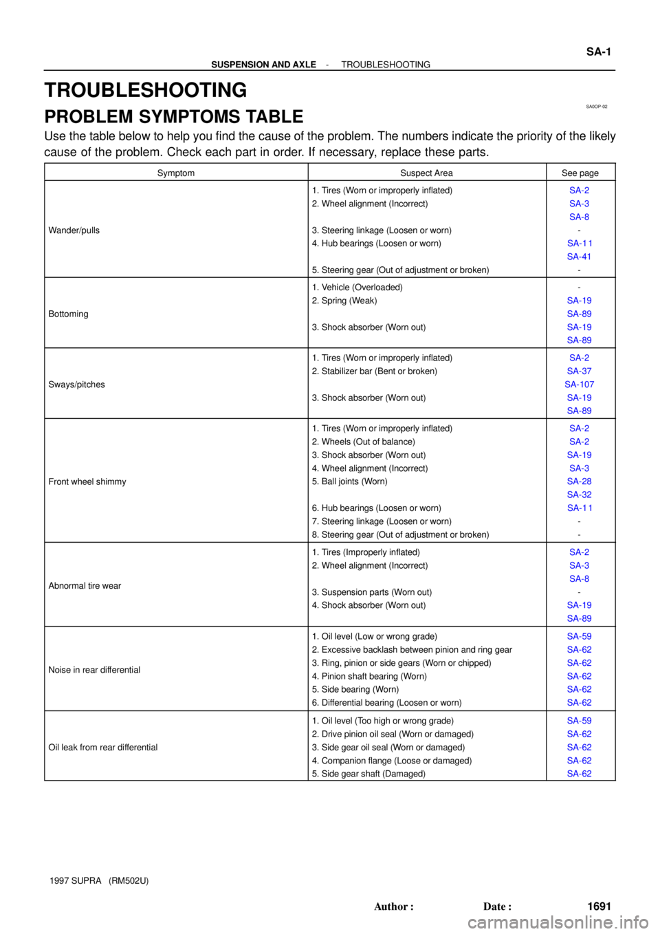
TROUBLESHOOTING
PROBLEM SYMPTOMS TABLE
Use the table below to help you find the cause of the problem. The numbers indicate the priority of the likely
cause of the problem. Check each part in order. If necessary, replace these parts.
SymptomSuspect AreaSee page
Wander/pulls
1. Tires (Worn or improperly inflated)
2. Wheel alignment (Incorrect)
3. Steering linkage (Loosen or worn)
4. Hub bearings (Loosen or worn)
5. Steering gear (Out of adjustment or broken)SA-2
SA-3
SA-8
-
SA-1 1
SA-41
-
Bottoming
1. Vehicle (Overloaded)
2. Spring (Weak)
3. Shock absorber (Worn out)-
SA-19
SA-89
SA-19
SA-89
Sways/pitches
1. Tires (Worn or improperly inflated)
2. Stabilizer bar (Bent or broken)
3. Shock absorber (Worn out)SA-2
SA-37
SA-107
SA-19
SA-89
Front wheel shimmy
1. Tires (Worn or improperly inflated)
2. Wheels (Out of balance)
3. Shock absorber (Worn out)
4. Wheel alignment (Incorrect)
5. Ball joints (Worn)
6. Hub bearings (Loosen or worn)
7. Steering linkage (Loosen or worn)
8. Steering gear (Out of adjustment or broken)SA-2
SA-2
SA-19
SA-3
SA-28
SA-32
SA-1 1
-
-
Abnormal tire wear
1. Tires (Improperly inflated)
2. Wheel alignment (Incorrect)
3. Suspension parts (Worn out)
4. Shock absorber (Worn out)SA-2
SA-3
SA-8
-
SA-19
SA-89
Noise in rear differential
1. Oil level (Low or wrong grade)
2. Excessive backlash between pinion and ring gear
3. Ring, pinion or side gears (Worn or chipped)
4. Pinion shaft bearing (Worn)
5. Side bearing (Worn)
6. Differential bearing (Loosen or worn)SA-59
SA-62
SA-62
SA-62
SA-62
SA-62
Oil leak from rear differential
1. Oil level (Too high or wrong grade)
2. Drive pinion oil seal (Worn or damaged)
3. Side gear oil seal (Worn or damaged)
4. Companion flange (Loose or damaged)
5. Side gear shaft (Damaged)SA-59
SA-62
SA-62
SA-62
SA-62