Page 135 of 1807

REMOVAL
1. DISCHARGE REFRIGERANT FROM REFRIGERATION
SYSTEM
HINT:
At the time of installation, please")
AC0QN-01
N08732
N16963
AC-40
- AIR CONDITIONINGRECEIVER
2188 Author�: Date�:
1997 SUPRA (RM502U)
REMOVAL
1. DISCHARGE REFRIGERANT FROM REFRIGERATION
SYSTEM
HINT:
At the time of installation, please refer to the following item.
Evacuate air from refrigeration system.
Charge system with refrigerant and inspect for leakage of refrig-
erant.
Specified amount: 700 ± 50 g (24.96 ± 1.76 oz.)
2. REMOVE FRONT BUMPER (See page BO-4)
3. REMOVE RADIATOR SUPPORT UPPER SEAL
Remove the 12 clips and radiator support upper seal.
4. REMOVE LIQUID TUBES FROM RECEIVER
Remove the 2 bolts and both tubes from the receiver.
Torque: 5.4 N´m (55 kgf´cm, 48 in.´lbf)
NOTICE:
Cap the open fittings immediately to keep moisture or dirt
out of the system.
HINT:
At the time of installation, please refer to the following item.
Lubricate 2 new O-rings with compressor oil and install the
tube.
5. REMOVE RECEIVER
Remove the holder bolt and pull the receiver downward from
the receiver holder.
HINT:
At the time of installation, please refer to the following item.
If receiver is replaced, add compressor oil to receiver.
Add 10 cc (0.34 fl.oz.)
Compressor oil: ND-OIL 8 or equivalent
6. REMOVE RECEIVER HOLDER
Remove the screw and holder.
Page 137 of 1807
N08731
N08730
N08726
N08727
AC-44
- AIR CONDITIONINGCONDENSER
2192 Author�: Date�:
1997 SUPRA (RM502U)
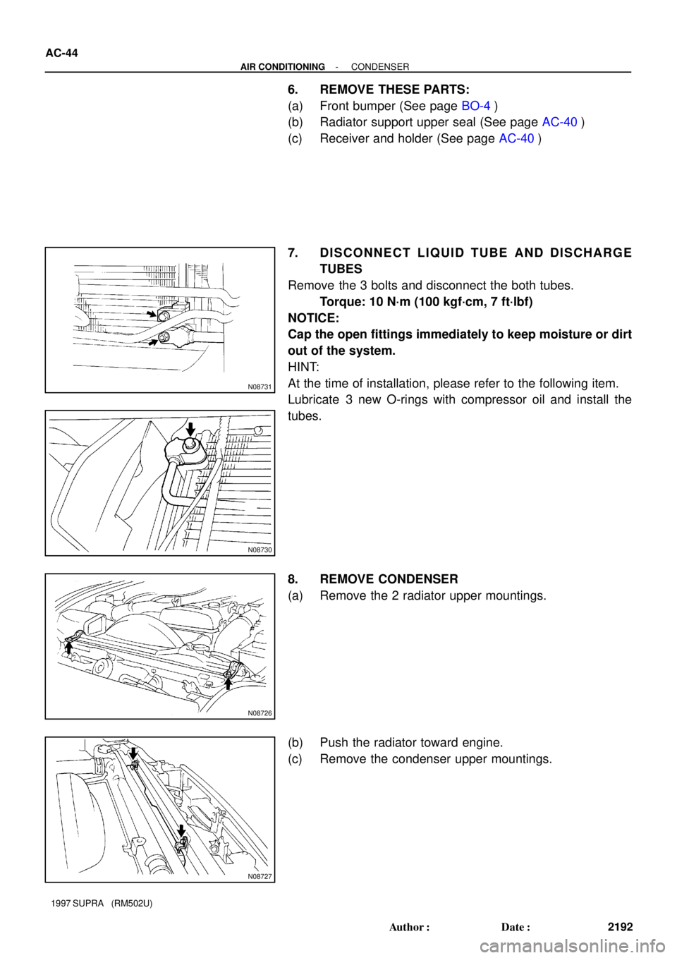
6. REMOVE THESE PARTS:
(a) Front bumper (See page BO-4)
(b) Radiator support upper seal (See page AC-40)
(c) Receiver and holder (See page AC-40)
7. DISCONNECT LIQUID TUBE AND DISCHARGE
TUBES
Remove the 3 bolts and disconnect the both tubes.
Torque: 10 N´m (100 kgf´cm, 7 ft´lbf)
NOTICE:
Cap the open fittings immediately to keep moisture or dirt
out of the system.
HINT:
At the time of installation, please refer to the following item.
Lubricate 3 new O-rings with compressor oil and install the
tubes.
8. REMOVE CONDENSER
(a) Remove the 2 radiator upper mountings.
(b) Push the radiator toward engine.
(c) Remove the condenser upper mountings.
Page 262 of 1807
BO0Q9-01
N19400
Front Fender Liner RH
Front Fender
Splash Shield RHEngine Upper Cover No.2
X12Front Fender liner LH
X12
Front Fender
Splash Shield LH Air Cleaner Cap X16
X6
Reinforcement
Hood to Front End
Panel Seal
Upper Center Retainer
Energy AbsorberHeadlightX6
Emblem
Lower Center Retainer
Side Marker
Light
Front Spoiler
Side Retainer RH Lower Radiator GrilleLower Center
No.2 Retainer
Side Marker Light
Front Spoiler
Retainer Upper No.3
Front License Plate
Mounting Bracket
Front Turn Signal and Parking LightFront Spoiler
Retainer Upper
RH
Front Spoiler
Retainer Lower No.1Front Spoiler
Side Retainer LH
Front Spoiler Cover
Front Spoiler
Retainer Upper LH
5.9 (60, 52 in.´lbf)
5.9 (60, 52 in.´lbf)N´m (kgf´cm, ft´lbf)
: Specified torque BO-4
- BODYFRONT BUMPER
2084 Author�: Date�:
1997 SUPRA (RM502U)
FRONT BUMPER
COMPONENTS
Page 389 of 1807
NO8903
NO8971
HINT: For symbols, capital letters indicate
right side of vehicle, small letters indicate
left side of vehicle (Seen from rear).
1,617
(63.66) 263
(10.35)652
(25.67) A-L, a-l C-")
mm (in.)NO8903
NO8971
HINT: For symbols, capital letters indicate
right side of vehicle, small letters indicate
left side of vehicle (Seen from rear).
1,617
(63.66) 263
(10.35)652
(25.67) A-L, a-l C-l, c-L G-g
Vehicle Dimensions
(Three-Dimensional Distance)
Symbol Name Hole dia. Symbol Name Hole dia.
A, a Front fender apron standard hole 10 (0.39) J, j Front side member reinforcement standard hole 8 (0.31)
B, b Front spring support hole-front 11 (0.43) Cooling fan installation nut 6 (0.24) nut
C, c Cowl top side panel standard hole 10 (0.39) L, l Front fender installation nut 6 (0.24) nut
Cowl top panel center mark M, m Hood hinge installation nut 8 (0.31) nut
E, e Front side member working hole 18 (0.71) N, n Headlight installation nut 6 (0.24) nut
F, f Front side member standard hole 13 (0.51) O, o Headlight installation hole
14x10.6
(0.55x0.42)
G, g Radiator duct installation hole 7.2 (0.283) P, p Headlight installation hole
H, h Radiator support apron brace standard hole 10 (0.39) Q, q Headlight installation hole
I, i Apron fender side extension standard hole 9 (0.35)
BODY DIMENSION DRAWINGS
ENGINE COMPARTMENT
D
14x9
(0.55x0.35)
14x9
(0.55x0.35)
K
BODY DIMENSIONSDI-3
Page 528 of 1807
CO08J-01
- COOLINGCOOLANT
CO-1
1414 Author�: Date�:
1997 SUPRA (RM502U)
COOLANT
INSPECTION
1. CHECK ENGINE COOLANT LEVEL AT RADIATOR RESERVOIR
The engine coolant level should be between the ºLOWº and ºFULLº lines, when the engine is cold.
If low, check for leaks and add engine coolant up to the ºFULLº line.
2. CHECK ENGINE COOLANT QUALITY
(a) Remove the radiator cap.
CAUTION:
To avoid the danger of being burned, do not remove the radiator cap while the engine and radiator
are still hot, as fluid and steam can be blown out under pressure.
(b) There should not be any excessive deposits of rust or scale around the radiator cap or radiator filler
hole, and the coolant should be free from oil.
If excessively dirty, replace the coolant.
(c) Reinstall the radiator cap.
Page 529 of 1807

REPLACEMENT
1. DRAIN ENGINE COOLANT
(a) Remove the radiator cap.
CAUTION:
To avoid the danger of")
CO0ZY-01
Z07402
Drain Plug
Drain Plug CO-2
- COOLINGCOOLANT
1415 Author�: Date�:
1997 SUPRA (RM502U)
REPLACEMENT
1. DRAIN ENGINE COOLANT
(a) Remove the radiator cap.
CAUTION:
To avoid the danger of being burned, do not remove the ra-
diator cap while the engine and radiator are still hot, as fluid
and steam can be blown out under pressure.
(b) Loosen the 2 drain plugs (for the engine and radiator),
and drain the coolant.
HINT:
To prevent the coolant from spraying over the cylinder block,
connect the rubber hose (inside diameter 6 - 8 mm) in the mar-
ket to the union pipe under.
(c) Close the drain plugs.
Torque:
Engine drain plug
29 N´m (300 kgf´cm, 22 ft´lbf)
2. FILL ENGINE COOLANT
(a) Slowly fill the system with coolant.
�Use a good brand of ethylene-glycol base coolant
and mix it according to the manufacturer's direc-
tions.
�Using coolant which includes more than 50 % ethyl-
ene-glycol (but not more than 70 %) is recom-
mended.
NOTICE:
�Do not use an alcohol type coolant.
�The coolant should be mixed with demineralized wa-
ter or distilled water.
Capacity (w/ Heater):
M/TA/T
2JZ-GE7.3 liters
(7.7 US qts, 6.4 lmp. qts)8.3 liters
(8.8 US qts, 7.3 lmp. qts)
2JZ-GTE8.9 liters
(9.4 US qts, 7.8 lmp. qts)8.8 liters
(9.3 US qts, 7.7 lmp. qts)
(b) Install the radiator cap.
(c) Start the engine, and bleed the cooling system.
(d) Refill the reservoir with coolant until it reaches the
ºFULLº line.
3. CHECK ENGINE COOLANT FOR LEAKS
Page 533 of 1807
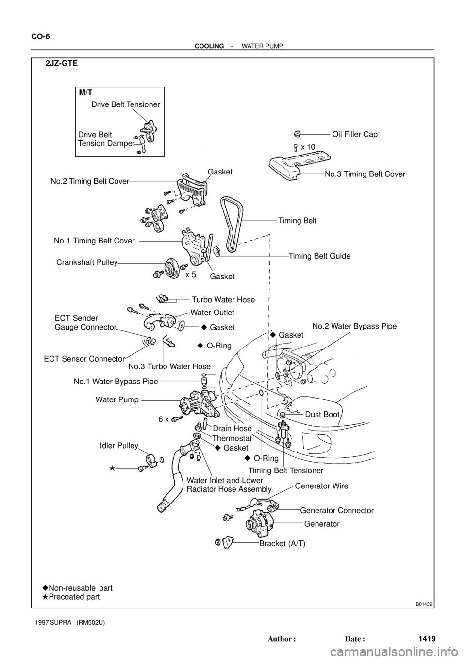
B01432
No.2 Timing Belt CoverDrive Belt Tensioner
No.1 Timing Belt Cover
Crankshaft PulleyOil Filler Cap
x 10
Timing Belt
Timing Belt Guide
No.2 Water Bypass Pipe
� Idler PulleyGasket
Drain Hose Water Pump
x 5
Dust Boot � Gasket
� O-Ring
� O-Ring � Gasket Thermostat
Timing Belt Tensioner
Generator Connector Generator Wire
Generator
Bracket (A/T) Water Inlet and Lower
Radiator Hose Assembly
�Precoated part
�Non-reusable part
6 x 2JZ-GTE
Gasket
Water Outlet
ECT Sender
Gauge Connector
ECT Sensor ConnectorTurbo Water Hose Drive Belt
Tension Damper
No.3 Timing Belt Cover
No.3 Turbo Water Hose� Gasket
No.1 Water Bypass Pipe
M/T
CO-6
- COOLINGWATER PUMP
1419 Author�: Date�:
1997 SUPRA (RM502U)
Page 545 of 1807

ON-VEHICLE INSPECTION
1. REMOVE RADIATOR CAP
CAUTION:
To avoid")
Z00570
Radiator Cap Tester
30° or More
Radiator Cap
P11504
CO08U-01
CO-18
- COOLINGRADIATOR
1431 Author�: Date�:
1997 SUPRA (RM502U)
ON-VEHICLE INSPECTION
1. REMOVE RADIATOR CAP
CAUTION:
To avoid the danger of being burned, do not remove the ra-
diator cap while the engine and radiator are still hot, as fluid
and steam can be blown out under pressure.
2. INSPECT RADIATOR CAP
NOTICE:
�If the radiator cap has contaminations, always rinse
it with water.
�When performing steps (a) and (b) below, keep the ra-
diator pump tester at an angle of over 30° above the
horizontal.
(a) Before using a radiator cap tester, wet the relief valve and
pressure valve with engine coolant or water.
(b) Using a radiator cap tester, slowly pump the tester and
check that air is coming from the vacuum valve.
Pump speed: 1 push/ (3 seconds or more)
NOTICE:
Push the pump at a constant speed.
If air is not coming from the vacuum valve, replace the radiator
cap.
(c) Pump the tester and measure the relief valve opening
pressure.
Pump speed: 1 push within 1 second
NOTICE:
This pump speed is for the first pump only (in order to close
the vacuum valve). After this, the pump speed can be re-
duced.
Standard opening pressure:
93 - 123 kPa (0.95 - 1.25 kgf/cm
2, 13.5 - 17.8 psi)
Minimum opening pressure:
78 kPa (0.8 kgf/cm
2, 11.4 psi)
HINT:
Use the tester's maximum reading as the opening pressure.
If the opening pressure is less than minimum, replace the radia-
tor cap.
3. INSPECT COOLING SYSTEM FOR LEAKS
(a) Fill the radiator with coolant, and attach a radiator cap tes-
ter.
(b) Warm up the engine.
(c) Pump it to 147 kPa (1.5 kgf/cm
2, 21.3 psi), and check that
the pressure does not drop.
If the pressure drops, check the hoses, radiator or water pump
for leaks.
If no external leaks are found, check the heater core, cylinder
block and cylinder head.
4. REINSTALL RADIATOR CAP