Page 5 of 1807
CL047-01
Q04338
CL-12
- CLUTCHCLUTCH RELEASE CYLINDER
1553 Author�: Date�:
1997 SUPRA (RM502U)
DISASSEMBLY
1. PULL OUT PUSH ROD WITH BOOT
2. REMOVE PISTON WITH SPRING
Using compressed air, remove the piston and spring from the
cylinder.
Page 6 of 1807
CL048-01
Z07291
- CLUTCHCLUTCH RELEASE CYLINDER
CL-13
1554 Author�: Date�:
1997 SUPRA (RM502U)
REASSEMBLY
1. COAT PISTON WITH LITHIUM SOAP BASE GLYCOL
GREASE, AS SHOWN
2. INSTALL PISTON WITH SPRING INTO CYLINDER
3. INSTALL BOOT WITH PUSH ROD TO CYLINDER
Page 17 of 1807
CL040-01
Z16903
Filler Cap
Reservoir Tank
Slotted Spring
Pin
Clutch Line
Push Rod � Grommet Float
Clip Pin
Clevis
Boot
Washer
� Snap Ring
Lock Nut15 (155, 11)
12 (125, 9)
12 (125, 9)
N´m (kgf´cm, ft´lbf)
: Specified torque
� Non-reusable partPiston
Master Cylinder Body
- CLUTCHCLUTCH MASTER CYLINDER
CL-5
1546 Author�: Date�:
1997 SUPRA (RM502U)
CLUTCH MASTER CYLINDER
COMPONENTS
Page 19 of 1807
CL042-01
Q04189
Q04190
- CLUTCHCLUTCH MASTER CYLINDER
CL-7
1548 Author�: Date�:
1997 SUPRA (RM502U)
DISASSEMBLY
1. REMOVE RESERVOIR TANK
(a) Using a pin punch and hammer, drive out the slotted
spring pin.
(b) Remove the reservoir tank and grommet.
2. REMOVE PUSH ROD
(a) Pull back the boot, and using snap ring pliers, remove the
snap ring.
(b) Pull out the push rod.
3. REMOVE PISTON
Page 22 of 1807

MT06N-01
D01920
Shift Lever Knob
Upper Console Panel
Shift Lever Boot
RetainerShift Lever Retainer
Shift and Select Lever
Boot No.1
x5
Service Hole
Cover
Starter
Pipe Support Bracket
Service Hole Cover
Ground Cable
Engine Under Cover
Oxygen SensorExhaust Front Pipe Exhaust Tail Pipe Exhaust Center PipePropeller ShaftCrossmember Brace
Heat Insulator Engine Rear
Mounting
Adjusting Washer BushingTransmission Shift Lever
Clutch Release Cylinder
N´m (kgf´cm, ft´lbf)Shift and Select Lever
Boot No.2
Oxygen Sensor Cover
: Specified torqueRear Engine Mounting
Member
� Non-reusable part� Gasket
�
� Gasket
� Gasket��
� Gasket
19 (195, 14)�
72 (730, 53)
12 (120, 9)
79 (805, 58)
49 (500, 36)
19 (195, 14)�
56 (570, 41)
12 (120, 9)
37 (380, 27)
12 (120, 9)
25 (260, 19)13 (135, 10)
39 (400, 29)
5.5 (55, 48 in.´lbf)
13 (130, 9)
13 (130, 9)
5.5 (55, 48 in.´lbf)
Heat Insulator72 (730, 53)
39 (400, 29)
25 (250, 18)19 (195, 14)
19 (195, 14)
7.8 (80, 69 in.´lbf)�
Bushing
�
19 (195, 14)
Normal Roof:
Sport Roof:
58 (590, 43)�
Transmission
Crossmember
Brace
20 (200, 14)
25 (250, 18)
�
58 (590, 43)�
MT-2
- MANUAL TRANSMISSION (V160)MANUAL TRANSMISSION UNIT
1570 Author�: Date�:
1997 SUPRA (RM502U)
MANUAL TRANSMISSION UNIT
COMPONENTS
Page 23 of 1807
MANUAL TRANSMISSION UNIT
MT-3
1571 Author�: Date�:
1997 SUPRA (RM502U)
REMOVAL
1. REM")
MT06O-01
Q04417
Q06365
Q09475
Filler Plug
Drain PlugOil Level
0 - 5 mm
Q04419
R06858
- MANUAL TRANSMISSION (V160)MANUAL TRANSMISSION UNIT
MT-3
1571 Author�: Date�:
1997 SUPRA (RM502U)
REMOVAL
1. REMOVE UPPER CONSOLE PANEL, SHIFT LEVER
BOOT RETAINER AND SHIFT AND SELECT LEVER
BOOTS NO.1 AND NO.2
(a) Remove the shift lever knob.
(b) Using a screwdriver, pry out the upper console panel.
(c) Remove the 4 bolts and boot retainer.
(d) Remove the shift and select lever boots No.1 and No.2.
2. REMOVE 4 TRANSMISSION SHIFT LEVER SET
BOLTS
Torque: 7.8 N´m (80 kgf´cm, 69 in.´lbf)
3. RAISE VEHICLE
NOTICE:
Make sure that the vehicle is securely supported.
4. DRAIN TRANSMISSION OIL
Oil type: TOYOTA GEAR OIL V160 or ESSO ATF
DEXRON®D-21065
Capacity: 1.8 liters (1.9 US qts, 1.6 Imp. qts)
Torque: 39 N´m (400 kgf´cm, 29 ft´lbf)
5. REMOVE ENGINE UNDER COVER
6. REMOVE EXHAUST FRONT PIPE AND PIPE SUP-
PORT BRACKET
(a) Remove the 2 nuts, cover, oxygen sensor and gasket.
Torque: 20 N´m (200 kgf´cm, 14 ft´lbf)
(b) Remove the 2 bolts, nuts and gasket.
Torque: 58 N´m (590 kgf´cm, 43 ft´lbf)
(c) Remove the 2 bolts and pipe support bracket from the
clutch housing.
Torque: 37 N´m (380 kgf´cm, 27 ft´lbf)
(d) Remove the 2 bolts, nuts and gasket.
Torque: 58 N´m (590 kgf´cm, 43 ft´lbf)
(e) Remove the exhaust front pipe.
Page 40 of 1807
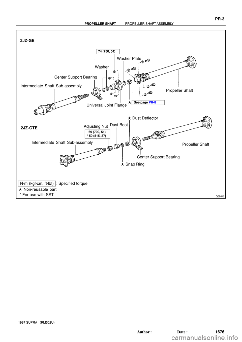
Q09642
2JZ-GE
2JZ-GTE Intermediate Shaft Sub-assemblyCenter Support BearingWasherWasher Plate
Universal Joint FlangePropeller Shaft
�
Intermediate Shaft Sub-assembly
Propeller Shaft
Center Support Bearing Adjusting NutDust Boot� Dust Deflector
� Snap Ring
� Non-reusable part: Specified torque
N´m (kgf´cm, ft´lbf)
See page PR-8
* For use with SST
69 (700, 51)
* 50 (515, 37)
74 (750, 54)
- PROPELLER SHAFTPROPELLER SHAFT ASSEMBLY
PR-3
1676 Author�: Date�:
1997 SUPRA (RM502U)
Page 46 of 1807

(2) Place the flange on the shaft")
R01132
Matchmarks
R01133
SST
R06958
Matchmarks
PR0239
Matchmarks
Q06357
SST
- PROPELLER SHAFTPROPELLER SHAFT ASSEMBLY
PR-9
1682 Author�: Date�:
1997 SUPRA (RM502U)
(2) Place the flange on the shaft and align the match-
marks.
HINT:
If replacing either the center flange or intermediate shaft, reas-
semble them so that the front yoke of the intermediate shaft and
the rear yoke of the propeller shaft are facing in the same direc-
tion.
(3) Install the washer.
(4) Using SST to hold the flange, press the bearing into
position by tightening down a new nut.
SST 09330-00021
Torque: 181 N´m (1,850 kgf´cm, 134 ft´lbf)
(5) Loosen the nut.
(6) Torque the nut again.
Torque: 69 N´m (700 kgf´cm, 51 ft´lbf)
(7) Using a punch and hammer, stake the shaft.
(e) Install the propeller shaft.
(1) Align the matchmarks on the flanges and connect
the flanges with 4 bolts, washers and nuts.
HINT:
If replacing either the center flange or intermediate shaft, reas-
semble them so that the front yoke of the intermediate shaft and
the rear yoke of the propeller shaft are facing in the same direc-
tion.
(2) Torque the 4 bolts and nuts.
Torque: 74 N´m (750 kgf´cm, 54 ft´lbf)
2. 2JZ-GTE:
REPLACE CENTER SUPPORT BEARING
(a) Separate the intermediate shaft and propeller shaft.
(1) Place matchmarks on the intermediate shaft and
propeller shaft.
(2) Separate the intermediate shaft and propeller shaft.
(3) Remove the dust boot from the propeller shaft.
HINT:
If the dust boot is reused, remove it after wrapping vinyl tape
around the spline, so it will not be damage.
(b) Remove the center support bearing.
(1) Using a snap ring expander, remove the snap ring.
(2) Using SST, remove the center support bearing with
dust deflector.
SST 09950-00020