Page 1668 of 1807
SA0PQ-02
W02907
Washer
Drive Shaft
Lower Suspension
Arm BraceLock Cap
Cotter Pin
Boot Clamp
Exhaust Pipe
Supprot Ring
Outboard Joint
with Drive Shaft Washer Washer
Washer
Boot Clamp Exhaust Pipe2JZ-GTE:
2JZ-GTE:
Boot Clamp Boot Clamp
Boot
Snap Ring
Inboard Joint
End Cover
Gasket
2JZ-GTE:
End CoverInboard Joint
Inboard Joint Cover
Boot Clamp
Boot Clamp
Boot
Non-reusable part SA-50
- SUSPENSION AND AXLEREAR DRIVE SHAFT
1740 Author�: Date�:
1997 SUPRA (RM502U)
REAR DRIVE SHAFT
COMPONENTS
Page 1669 of 1807

REMOVAL
1. REMOVE REAR WHEEL
Torque: 103 N´m")
SA0PR-02
Z08967
TailpipeCenter Pipe
R07037
Matchmarks
R07024
R06937
- SUSPENSION AND AXLEREAR DRIVE SHAFT
SA-51
1741 Author�: Date�:
1997 SUPRA (RM502U)
REMOVAL
1. REMOVE REAR WHEEL
Torque: 103 N´m (1,050 kgf´cm, 76 ft´lbf)
2. DISCONNECT EXHAUST PIPE SUPPORTS
(a) Remove the 2 exhaust pipe support rings.
(b) Support the exhaust pipe securely.
(c) Remove the 2 exhaust pipe support O-rings.
3. REMOVE COTTER PIN, LOCK CAP AND LOCK NUT
(a) Remove the cotter pin and lock cap.
(b) With applying the brakes, remove the nut.
Torque: 289 N´m (2,950 kgf´cm, 213 ft´lbf)
4. REMOVE LOWER SUSPENSION ARM BRACE
Remove the 4 bolts and lower suspension arm brace.
Torque: 18 N´m (180 kgf´cm, 13 ft´lbf)
5. REMOVE REAR DRIVE SHAFT
(a) Place matchmarks on the drive shaft and side gear shaft.
(b) 2JZ-GE:
Using 8 mm hexagon wrench, remove the 6 hexagon
bolts and 3 washers with applying the brakes.
Torque: 68 N´m (695 kgf´cm, 50 ft´lbf)
(c) 2JZ-GTE:
Using a 10 mm hexagon wrench, remove the 6 hexagon
bolts and 2 washers with applying the brakes.
Torque: 83 N´m (850 kgf´cm, 61 ft´lbf)
(d) Disconnect the inboard joint from the differential side gear
shaft.
(e) Hold the inboard joint side of the drive shaft so that the
outboard joint side does not bend too much.
(f) Using a hammer, lightly tap the end of the drive shaft to
disengage the axle hub and remove the drive shaft.
NOTICE:
�Be careful not to damage the boots and speed sensor
rotor of the drive shaft, and oil seal of the axle hub.
�At the time of installation, make sure the outboard
joint side of the drive shaft does not bend too much.
Page 1670 of 1807

DISASSEMBLY
1. CHECK DRIVE SHAFT
(a) Check that operation of t")
SA0PS-01
R05813
R00195
R11083Matchmarks
R00191
SST SA-52
- SUSPENSION AND AXLEREAR DRIVE SHAFT
1742 Author�: Date�:
1997 SUPRA (RM502U)
DISASSEMBLY
1. CHECK DRIVE SHAFT
(a) Check that operation of the joint is smooth within the slid-
ing region in the axial direction.
HINT:
If a large angle is used for the cross-groove type joint, the joint
will feel like it is catching, but this does not indicate an abnormal-
ity.
(b) Check that the boots are not cracked, damaged or leak-
ing.
(c) Check that there are no scratches on the speed sensor
rotor.
2. REMOVE END COVER
(a) Using a screwdriver, remove the end cover.
(b) Use bolts, nuts and washers to keep the inboard joint to-
gether.
NOTICE:
Tighten the bolt by hand to avoid scratching the flange sur-
face.
3. REMOVE BOOT CLAMPS
Using a side cutter or pliers, remove the 4 boot clamps.
4. REMOVE INBOARD JOINT
(a) Place matchmarks on the inboard joint and drive shaft.
(b) Using a snap ring expander, remove the snap ring.
(c) Using SST, an extension bar and a press, remove the in-
board joint from the drive shaft.
SST 09726-12023 (09726-01031)
Page 1671 of 1807
SA0726
- SUSPENSION AND AXLEREAR DRIVE SHAFT
SA-53
1743 Author�: Date�:
1997 SUPRA (RM502U)
(d) Mount the inboard joint in a soft jaw vise.
(e) Using a screwdriver and hammer, remove the inboard
joint cover from the inboard joint.
NOTICE:
Make sure the cage and inner race are not positioned too
much to one side of the outer race.
5. REMOVE BOOTS FROM DRIVE SHAFT
Remove the inboard joint boot and outboard boot.
Page 1672 of 1807

REASSEMBLY
1. ASSEMBLE INBOARD JOINT
If t")
SA1TE-01
SA0721
Matchmarks
SA1328
Narrow
Wide
SA0830
R 11111
Vinyl tape SA-54
- SUSPENSION AND AXLEREAR DRIVE SHAFT
1744 Author�: Date�:
1997 SUPRA (RM502U)
REASSEMBLY
1. ASSEMBLE INBOARD JOINT
If the joint has come apart, reassemble it in the following order.
(a) Align the matchmarks placed before removal.
HINT:
When the matchmarks have disappeared, do the following pro-
cedure.
(1) Install the inner race to the cage so that the in-
dented bevelled part of the inner race is on the op-
posite side to the bevelled top of the cage.
(2) Install the outer race so that the indented side of the
outer race is facing the same side as the bevelled
surface of the cage.
(3) Match the narrow projections of the inner race with
the wide projections of the outer race.
(b) Tilt the cage and inner race to the side and insert the balls
one by one.
NOTICE:
When the cage and inner race are tilted over, support the
joint with your hand to prevent the balls from falling out.
2. TEMPORARILY INSTALL 2 NEW BOOTS AND 4 NEW
BOOT CLAMPS
(a) Place 4 new boot clamps to the boots.
HINT:
Before installing the boots, wrap vinyl tape around the spline of
the shaft to prevent damaging the boots.
(b) Install 2 boots to the drive shaft.
Page 1673 of 1807
 1.0 - 1.8 mm
Z08195
Cover
R00194
Matchmarks
R08197
- SUSPENSION AND AXLEREAR DRIVE SHAFT
SA-55
1745 Author�: Date�:
1997 SUPRA (RM502U)
3. INSTALL INBOA")
SA0679
FIPG
Seal Diameter
(0.039 -
0.071 in.) 1.0 - 1.8 mm
Z08195
Cover
R00194
Matchmarks
R08197
- SUSPENSION AND AXLEREAR DRIVE SHAFT
SA-55
1745 Author�: Date�:
1997 SUPRA (RM502U)
3. INSTALL INBOARD JOINT COVER
(a) Apply FIPG to the inboard joint cover as shown in the il-
lustration.
FIPG:
Part No.08826-00801, THREE BOND 1121 or equiva-
lent
Install a nozzle that is cut to 1 mm (0.04 in.) opening.
HINT:
Avoid applying an excessive amount to the surface.
(b) Clean the surface of the inboard joint facing the cover.
(c) Align the bolt holes of the cover with those of the inboard
joint, then insert the hexagon bolts.
(d) Use a plastic hammer to tap the rim of the inboard joint
cover in place. Do this in the order shown, and repeat sev-
eral times.
4. INSTALL INBOARD JOINT
(a) Align the matchmarks placed before removal.
(b) Using a brass bar and hammer, install the inboard joint
onto the drive shaft.
NOTICE:
Check that the brass bar is touching the inner race, and not
the cage.
(c) Using a snap ring expander, install a new snap ring.
5. ASSEMBLE BOOTS TO JOINTS
Before assembling the boot, pack with only the same amount
of grease that was wiped off.
Grease capacity:
Inboard and Outboard joint:
100 - 105 g (3.5 - 3.7 oz.)
HINT:
Use the grease supplied in the boot kit.
NOTICE:
�Keep grease off the joint connection groove of the
boot.
�Pack with grease all over the ball contact surface in-
side the joint.
Page 1674 of 1807

or less
SST
R08199
SA1465
SA-56
- SUSPENSION AND AXLEREAR DRIVE SHAFT
1746 Author�: Date�:
1997 SUPRA (RM502U)
6. 2JZ-GTE:
INSTALL NEW BOOT CLAMPS TO BOTH")
W00623
SST
30°
R06938
0.8 mm (0.031 in.)
or less
SST
R08199
SA1465
SA-56
- SUSPENSION AND AXLEREAR DRIVE SHAFT
1746 Author�: Date�:
1997 SUPRA (RM502U)
6. 2JZ-GTE:
INSTALL NEW BOOT CLAMPS TO BOTH BOOTS
(a) Position the clamp onto the boot.
HINT:
Pinch the inboard side of the boot clamp, as shown in the il-
lustration.
(b) Place SST onto the clamp.
SST 09521-24010
(c) Tighten the SST so that the clamp is pinched.
NOTICE:
Do not overtighten the clamp by the SST.
(d) Using SST, adjust the clearance of the clamp.
SST 09240-00020
Clearance: 0.8 mm (0.031 in.) or less
(e) The drive shaft is designed to move ±20 mm from the
standard position.
Drive shaft standard length
RHLH
M/T598.5 mm (23.602 in.)547.5 mm (21.555 in.)
A/T598.5 mm (23.602 in.)553.5 mm (21.791 in.)
7. 2JZ-GE:
INSTALL NEW BOOT CLAMPS TO BOTH BOOTS
(a) Be sure the boot is on the shaft groove.
(b) Using a screwdriver, bend the clamp and lock it as shown.
(c) The drive shaft is designed to move ± 20 mm from stan-
dard position.
Drive shaft standard length
RH582.4 mm (22.929 in.)
LH537.4 mm (21.157 in.)
Page 1675 of 1807
Z04028
R07026
- SUSPENSION AND AXLEREAR DRIVE SHAFT
SA-57
1747 Author�: Date�:
1997 SUPRA (RM502U)
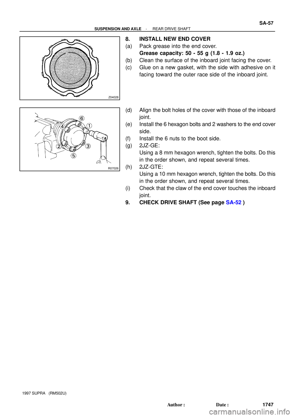
8. INSTALL NEW END COVER
(a) Pack grease into the end cover.
Grease capacity: 50 - 55 g (1.8 - 1.9 oz.)
(b) Clean the surface of the inboard joint facing the cover.
(c) Glue on a new gasket, with the side with adhesive on it
facing toward the outer race side of the inboard joint.
(d) Align the bolt holes of the cover with those of the inboard
joint.
(e) Install the 6 hexagon bolts and 2 washers to the end cover
side.
(f) Install the 6 nuts to the boot side.
(g) 2JZ-GE:
Using a 8 mm hexagon wrench, tighten the bolts. Do this
in the order shown, and repeat several times.
(h) 2JZ-GTE:
Using a 10 mm hexagon wrench, tighten the bolts. Do this
in the order shown, and repeat several times.
(i) Check that the claw of the end cover touches the inboard
joint.
9. CHECK DRIVE SHAFT (See page SA-52)