Page 533 of 1807
B01432
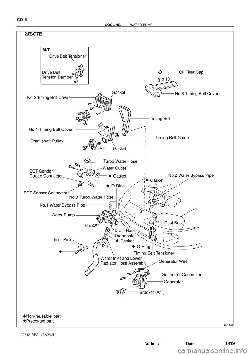
No.2 Timing Belt CoverDrive Belt Tensioner
No.1 Timing Belt Cover
Crankshaft PulleyOil Filler Cap
x 10
Timing Belt
Timing Belt Guide
No.2 Water Bypass Pipe
� Idler PulleyGasket
Drain Hose Water Pump
x 5
Dust Boot � Gasket
� O-Ring
� O-Ring � Gasket Thermostat
Timing Belt Tensioner
Generator Connector Generator Wire
Generator
Bracket (A/T) Water Inlet and Lower
Radiator Hose Assembly
�Precoated part
�Non-reusable part
6 x 2JZ-GTE
Gasket
Water Outlet
ECT Sender
Gauge Connector
ECT Sensor ConnectorTurbo Water Hose Drive Belt
Tension Damper
No.3 Timing Belt Cover
No.3 Turbo Water Hose� Gasket
No.1 Water Bypass Pipe
M/T
CO-6
- COOLINGWATER PUMP
1419 Author�: Date�:
1997 SUPRA (RM502U)
Page 1308 of 1807
S00926
Upper Console Panel
Shift & Select Lever BootShift Lever
Shift Lever Knob
Shift Control Rod
Fuel Return Hose
Fuel Inlet Hose A/T
PS Vane Pump
A/C CompressorGround Strap
PS Pump Bracket M/T
Clutch Release Cylinder (M/T)Rear Support Member
Exhaust Pipe AssemblyPropeller Shaft
PS Pressure Feed Hose
No.2 Front Exhaust Pipe
Pipe Support BracketHeated Oxygen SensorHeat InsulatorCenter Floor
Crossmember Brace Ring
Ring � Gasket
� Gasket
� Gasket
�
� Non-reusable partSport Roof � EM-56
- ENGINE MECHANICAL (2JZ-GTE)ENGINE UNIT
1161 Author�: Date�:
1997 SUPRA (RM502U)
Page 1313 of 1807
ENGINE UNIT
EM-61
1166 Author�: Date�:
1997 SUPRA (RM502U)
20. DISCONNECT ENGINE WIRE FROM CABIN
(a) Remove")
P11984
P11768
Z16718
M/T
Z16719
M/T
Z16720
M/T
Ground Strap
- ENGINE MECHANICAL (2JZ-GTE)ENGINE UNIT
EM-61
1166 Author�: Date�:
1997 SUPRA (RM502U)
20. DISCONNECT ENGINE WIRE FROM CABIN
(a) Remove the scuff plate.
(b) Take out the front side of the floor carpet.
(c) Remove the 2 nuts and ECM protector.
(d) Remove the nut, and disconnect the ECM from the floor
panel.
(e) Disconnect the 2 connectors from the ECM.
(f) Disconnect the connector from the TRAC ECU.
(g) Disconnect the connector from the instrument panel wire.
(h) Disconnect the 2 connectors from the connector cas-
sette.
(i) Pull out the engine wire from the cabin.
21. M/T:
REMOVE UPPER CONSOLE PANEL, SHIFT LEVER
BOOTS AND HOLDING BOLTS
(a) Remove the shift lever knob.
(b) Using a screwdriver, pry out the upper console panel.
(c) Remove the 4 bolts holding the lever boot to the transmis-
sion cover.
(d) Remove the shift & select lever boots.
(e) Remove the 4 bolts holding the shift lever to the shift lever
retainer.
22. M/T:
DISCONNECT CLUTCH RELEASE CYLINDER AND
GROUND STRAP FROM TRANSMISSION
(a) Remove the 2 bolts, and disconnect clutch release cylin-
der.
(b) Remove the bolt, and disconnect the clutch line tube.
(c) Remove the bolt, and disconnect ground strap.
Page 1320 of 1807
ENGINE UNIT
1173 Author�: Date�:
1997 SUPRA (RM502U)
17. INSTALL HEATED OXYGEN SENSOR
Install a new gasket, the oxygen sensor and sensor cover with")
P11986
Insert EM-68
- ENGINE MECHANICAL (2JZ-GTE)ENGINE UNIT
1173 Author�: Date�:
1997 SUPRA (RM502U)
17. INSTALL HEATED OXYGEN SENSOR
Install a new gasket, the oxygen sensor and sensor cover with
the 2 nuts.
Torque: 20 N´m (200 kgf´cm, 14 ft´lbf)
18. M/T:
INSTALL CLUTCH RELEASE CYLINDER AND
GROUND STRAP
(a) Install the clutch release cylinder with the 2 bolts.
Torque: 13 N´m (130 kgf´cm, 9 ft´lbf)
(b) Connect the clutch line tube with the bolt.
Torque: 37 N´m (380 kgf´cm, 27 ft´lbf)
(c) Install the ground strap with the bolt.
Torque: 37 N´m (380 kgf´cm, 27 ft´lbf)
19. CONNECT ENGINE WIRE TO CABIN
(a) Push in the engine wire through the cowl panel.
NOTICE:
Be careful not to damage the engine wire.
(b) Connect the 2 connectors to the connector cassette.
(c) Connect the connector to the instrument panel wire con-
nector.
(d) Connect the 2 connectors to the ECM.
(e) Connect the connector to the TRAC ECU.
(f) Insert the ECM bracket into the stay on the floor panel.
(g) Install the ECM with the nut.
(h) Install the ECM protector with the 2 nuts.
(i) Install the floor carpet.
(j) Install the scuff plate.
20. M/T:
INSTALL UPPER CONSOLE PANEL, SHIFT LEVER
BOOTS AND HOLDING BOLTS
21. CONNECT ENGINE WIRE TO COWL PANEL
22. INSTALL A/C COMPRESSOR
(a) Using a torx socket (E10), install the stud bolt and com-
pressor.
Torque: 26 N´m (265 kgf´cm, 19 ft´lbf)
(b) Connect the compressor connector.
(c) Temporarily install the compressor with nut and 3 bolts.
(d) Alternately tighten the bolt and nut.
Torque: 52 N´m (530 kgf´cm, 38 ft´lbf)
23. INSTALL PS PRESSURE FEED HOSE
Install the pressure feed hose with the 2 clamp bolts.
Page 1366 of 1807
TIMING BELT
EM-23
1128 Author�: Date�:
1997 SUPRA (RM502U)
(b) Using SST, align the timing marks of the cams")
A02558SST
A02562
Z02446
1.5 mm
Hexagon
Wrench
P04459
P11756
- ENGINE MECHANICAL (2JZ-GTE)TIMING BELT
EM-23
1128 Author�: Date�:
1997 SUPRA (RM502U)
(b) Using SST, align the timing marks of the camshaft timing
pulleys and No.4 timing belt cover.
SST 09960-10010 (09962-01000, 09963-01000)
10. INSTALL TIMING BELT
HINT:
(When re-using timing belt):
Align the matchmarks of the timing belt and camshaft timing
pulleys.
(a) Remove any oil or water on the camshaft timing pulley,
and keep it clean.
(b) Install the timing belt, checking the tension between the
crankshaft timing pulley and exhaust camshaft timing
pulley.
11. SET TIMING BELT TENSIONER
(a) Using a press, slowly press in the push rod using 981 -
9,807 N (100 - 1,000 kgf, 220 - 2,205 lbf) of force.
(b) Align the holes of the push rod and housing, pass a 1.5
mm hexagon wrench through the holes to keep the push
rod retracted.
(c) Release the press.
(d) Install the dust boot onto the tensioner.
12. INSTALL TIMING BELT TENSIONER
(a) Temporarily install the tensioner with the 2 bolts.
(b) Alternately tighten the 2 bolts.
Torque: 26 N´m (270 kgf´cm, 20 ft´lbf)
Page 1373 of 1807
LU04U-02
S00606
2JZ-GE
No.3 Timing Belt Cover
Oil Filler Cap
Crankshaft Position Sensor
Timing Belt
PlateOil Level Sensor
Connector
� Non-reusable partOil Dipstick and
Guide
Timing Belt
Oil Pan Baffle Plate Oil Level SensorNo.1 Oil Pan
Oil Strainer
No.2 Oil Pan Timing Belt Guide
No.1 Timing Belt Cover
Crankshaft Pulley No.2 Timing
Belt Cover
Drive Belt
Tensioner� O-Ring x 9
� Gasket � Crankshaft Front Oil Seal
� Precoated partOil Pump
Crankshaft Timing Pulley
Gasket
x 16
x 5
x 16
� Gasket Generator
� O-Ring� O-Ring
� Gasket Idler Pulley
�
x 6
x 5
Dust Boot
Timing Belt Tensionerx 6
Gasket LU-6
- LUBRICATIONOIL PUMP
1453 Author�: Date�:
1997 SUPRA (RM502U)
OIL PUMP
COMPONENTS
Page 1374 of 1807
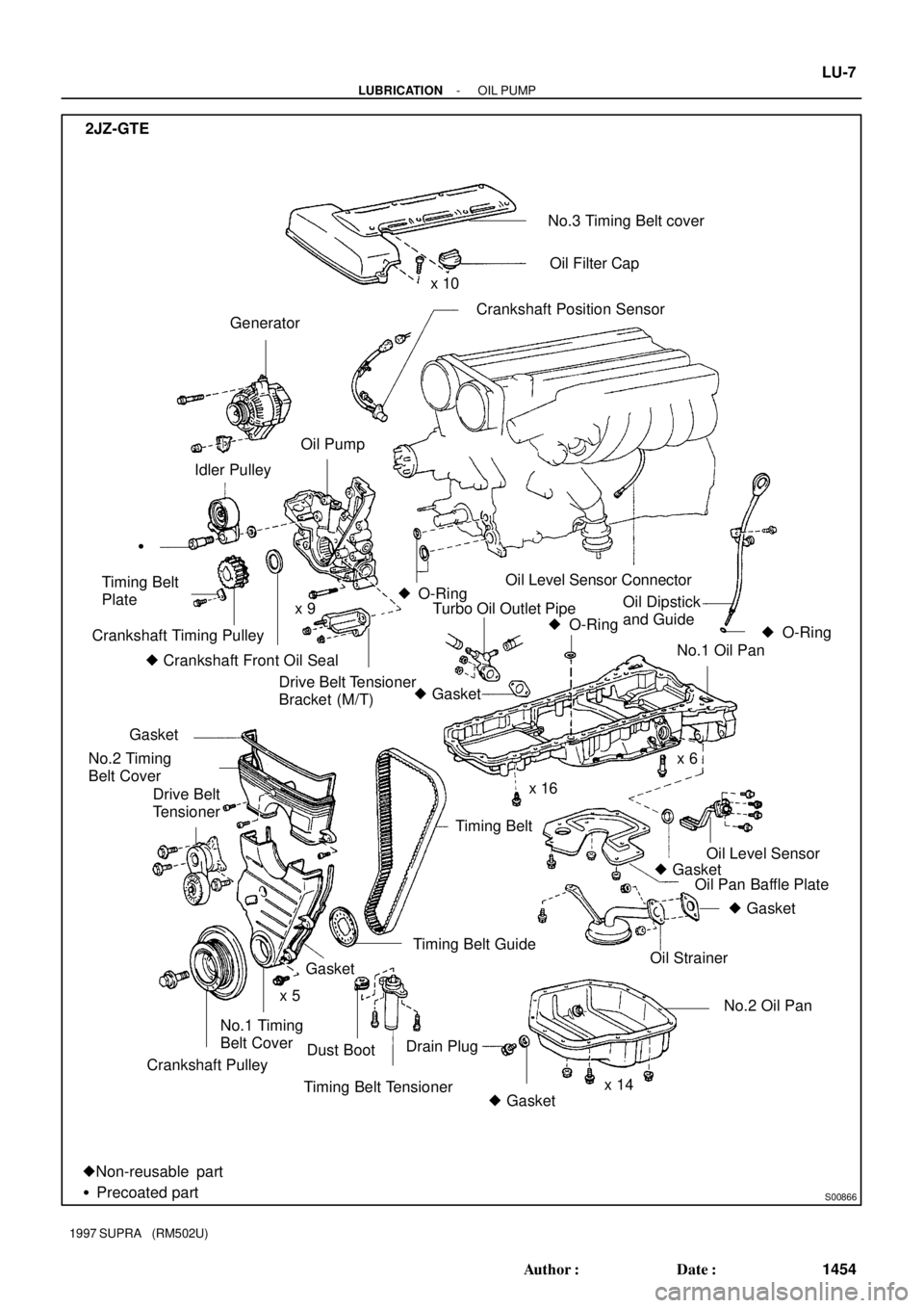
S00866
No.3 Timing Belt cover
Crankshaft Position Sensor
Oil Level Sensor ConnectorOil Filter Cap
Generator
Oil Strainer Oil Pump
� O-Ring
Turbo Oil Outlet Pipe Timing Belt
Plate
Crankshaft Timing Pulley
� Crankshaft Front Oil SealNo.1 Oil Pan Idler Pulley
� O-Ring �
Drive Belt Tensioner
Bracket (M/T)
Timing Belt GuideOil Level Sensor
� Gasket
Timing Belt Tensioner No.1 Timing
Belt Cover
Crankshaft PulleyDust BootDrain Plug
� GasketNo.2 Oil Pan
�Non-reusable part
�Precoated part� O-Ring
� Gasket
Timing Belt x 10
Oil Pan Baffle Plate Oil Dipstick
and Guide
Gasket
No.2 Timing
Belt Cover
Drive Belt
Tensionerx 6
x 5
x 14 x 16 2JZ-GTE
Gasket x 9
� Gasket
- LUBRICATIONOIL PUMP
LU-7
1454 Author�: Date�:
1997 SUPRA (RM502U)
Page 1395 of 1807
S00394
P02273
A02562
P11528
A02563
EM-16
- ENGINE MECHANICAL (2JZ-GTE)TIMING BELT
1121 Author�: Date�:
1997 SUPRA (RM502U)
8. SET NO.1 CYLINDER TO TDC/COMPRESSION
(a) Turn the crankshaft pulley, and align its groove with timing
mark º0º of the No.1 timing belt cover.
NOTICE:
Always turn the crankshaft clockwise.
(b) Check that the timing marks of the camshaft timing pul-
leys are aligned with the timing marks of the No.4 timing
belt cover.
If not, turn the crankshaft 1 revolution (360°).
9. REMOVE TIMING BELT FROM CAMSHAFT TIMING
PULLEYS
HINT:
(Re-using timing belt):
Place matchmarks on the timing belt and camshaft timing pul-
leys as shown in the illustration.
(a) Alternately loosen the 2 bolts, and remove them, the ten-
sioner and dust boot.
(b) Disconnect the timing belt from the camshaft timing pul-
leys.