Page 47 of 1807

(c) Install a new center support bearing.
(1) Using SST and")
PR0228
SST
R07314
SST
PR0229
SST
PR0238Vinyl Tape PR-10
- PROPELLER SHAFTPROPELLER SHAFT ASSEMBLY
1683 Author�: Date�:
1997 SUPRA (RM502U)
(c) Install a new center support bearing.
(1) Using SST and a press, install the center support
bearing.
SST 09330-50010
(2) Using SST and a press, insert a new dust deflector
until it almost touches the rubber of the center sup-
port bearing.
SST 09608-00071, 09608-06041
(3) Using SST and a press, install the dust deflector to
the end.
SST 09330-50010
(4) Using a snap ring expander, install a new snap ring.
(d) Assemble the intermediate shaft and propeller shaft.
(1) Install the dust boot.
NOTICE:
Assemble after wrapping vinyl tape around the spline so it
will not damage the boot.
(2) Apply grease to the spline.
Grease:
Molybdenum disulfide lithium base, NLGI No.2.
(3) Align the matchmarks and assemble the intermedi-
ate shaft and propeller shaft.
(4) Cover the adjusting nut with the dust boot.
(5) Tighten the adjusting nut fully by hand.
Page 48 of 1807
 : Specified torque
� Non-reusable partCylinder
Piston
Push Rod
Washer
Snap Ring
Boot
� Gasket")
IN04A-01
N17080
Filler Cap
Float
Reservoir Tank
� Grommet
Clip
Slotted Spring Pin
N´m (kgf´cm, ft´lbf) : Specified torque
� Non-reusable partCylinder
Piston
Push Rod
Washer
Snap Ring
Boot
� Gasket
Lock Nut
Clevis Pin
Clevis
12 ( 120, 9)
15 ( 155, 11)
- INTRODUCTIONHOW TO USE THIS MANUAL
IN-1
1 Author�: Date�:
1997 SUPRA (RM502U)
HOW TO USE THIS MANUAL
GENERAL INFORMATION
1. INDEX
An INDEX is provided on the first page of each section to guide you to the item to be repaired. To assist you
in finding your way through the manual, the Section Title and major heading are given at the top of every
page.
2. GENERAL DESCRIPTION
At the beginning of each section, a General Description is given that pertains to all repair operations con-
tained in that section.
Read these precautions before starting any repair task.
3. TROUBLESHOOTING
TROUBLESHOOTING tables are included for each system to help you diagnose the problem and find the
cause. The fundamentals of how to proceed with troubleshooting are described on page IN-17. Be sure to
read this before performing troubleshooting.
4. PREPARATION
Preparation lists the SST (Special Service Tools), recommended tools, equipment, lubricant and SSM (Spe-
cial Service Materials) which should be prepared before beginning the operation and explains the purpose
of each one.
5. REPAIR PROCEDURES
Most repair operations begin with an overview illustration. It identifies the components and shows how the
parts fit together.
Example:
Page 331 of 1807
W02668
Cap
Strainer
ReservoirSnap Ring
Boot
No.1 Piston and Spring
No.2 Piston and Spring
Reservoir Set Screw Grommet
Piston Stopper Bolt
� Gasket
� Non-reusable part
Lithium soap base glycol grease
- BRAKEBRAKE MASTER CYLINDER
BR-1 1
1811 Author�: Date�:
1997 SUPRA (RM502U)
Page 333 of 1807

DISASSEMBLY
1. REMOVE MASTER CYLINDER BOOT
Using a screwdriver, remove the master cylinder b")
BR0GG-01
W02792
W02660
W02661
- BRAKEBRAKE MASTER CYLINDER
BR-13
1813 Author�: Date�:
1997 SUPRA (RM502U)
DISASSEMBLY
1. REMOVE MASTER CYLINDER BOOT
Using a screwdriver, remove the master cylinder boot.
NOTICE:
At the time of reassembly, please refer to the following
item.
Facing the UP mark on the master cylinder boot upwards,
install the cylinder boot to the master cylinder.
2. REMOVE RESERVOIR CAP AND STRAINER
3. REMOVE RESERVOIR
Remove the set screw and pull out the reservoir.
Torque: 1.8 N´m (18 kgf´cm, 16 in.´lbf)
4. REMOVE 2 GROMMETS
5. PLACE CYLINDER IN VISE
6. REMOVE PISTON STOPPER BOLT
Using a screwdriver, push the pistons in all the way and remove
the No.2 piston stopper bolt and gasket.
Torque: 10 N´m (100 kgf´cm, 7 ft´lbf)
7. REMOVE 2 PISTONS
(a) Push in the piston with a screwdriver and remove the
snap ring with snap ring pliers.
HINT:
Tape the screwdriver tip before use.
(b) Remove the No. 1 piston and spring by hand, pulling
straight out, not at an angle.
NOTICE:
�If pulled out and install at an angle, there is a possibil-
ity that the cylinder bore could be damaged.
�At the time of reassembly, be careful not to damage
the rubber lips on the pistons.
Page 342 of 1807
BR0GY-02
W00802
Caliper
Anti-rattle
Spring
Pin Bleeder Plug
� Gasket
Disc
Piston Seal
Piston
Set RingPad SpacerAnti-squeal
Shim
Pad Clip
Boot
� Non-reusable part
Lithium soap base glycol grease
Disc brake grease BR-36
- BRAKEFRONT BRAKE CALIPER (2JZ-GTE)
1836 Author�: Date�:
1997 SUPRA (RM502U)
FRONT BRAKE CALIPER (2JZ-GTE)
COMPONENTS
Page 344 of 1807
BR0H0-01
R07133
Z09007
170 mm
(6.70 in.)50 mm
(1.97 in.)
30 mm
(1.18 in.)
R07134
R07135
BR-38
- BRAKEFRONT BRAKE CALIPER (2JZ-GTE)
1838 Author�: Date�:
1997 SUPRA (RM502U)
DISASSEMBLY
1. REMOVE CYLINDER BOOT SET RINGS AND BOOTS
Using a screwdriver, remove the 4 cylinder boot set rings and
4 boots.
2. REMOVE PISTONS FROM CYLINDER
(a) Prepare a wooden plate to hold the pistons.
(b) Place the plate between the pistons and insert a pad on
one side.
(c) Use compressed air to remove the pistons alternately
from the cylinder.
CAUTION:
Do not place your fingers in front of the pistons when using
compressed air.
3. REMOVE PISTON SEALS
Using a screwdriver, remove the 4 piston seals from the cylin-
der.
Page 349 of 1807
BR0HE-02
W00804
� Non-reusable part
Lithium soap base glycol grease
Disc brake greaseBreeder PlugCaliper
Anti-rattle
Spring
� Gasket � Gasket
DiscClip
Pad
Piston Seal
Piston
BootSet Ring
Inner Anti-squeal
ShimAnti-squeal
Shim
Pin BR-54
- BRAKEREAR BRAKE CALIPER (2JZ-GTE)
1854 Author�: Date�:
1997 SUPRA (RM502U)
REAR BRAKE CALIPER (2JZ-GTE)
COMPONENTS
Page 351 of 1807
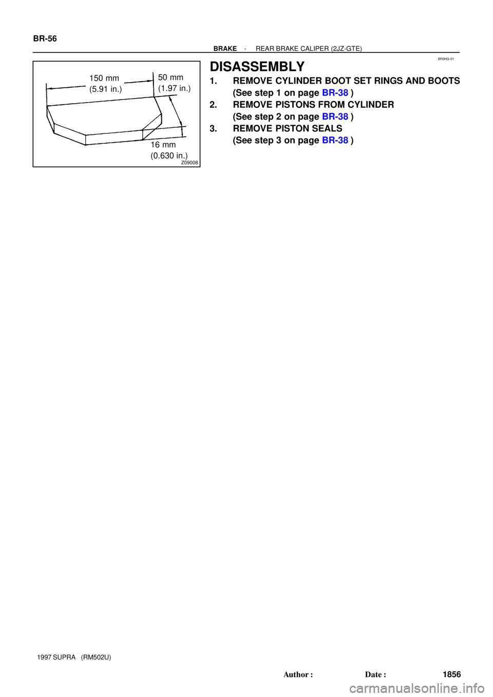
BR0HG-01
Z09008
150 mm
(5.91 in.)50 mm
(1.97 in.)
16 mm
(0.630 in.) BR-56
- BRAKEREAR BRAKE CALIPER (2JZ-GTE)
1856 Author�: Date�:
1997 SUPRA (RM502U)
DISASSEMBLY
1. REMOVE CYLINDER BOOT SET RINGS AND BOOTS
(See step 1 on page BR-38)
2. REMOVE PISTONS FROM CYLINDER
(See step 2 on page BR-38)
3. REMOVE PISTON SEALS
(See step 3 on page BR-38)