Page 54 of 1807

N02541DLC2
IN0247
N08868
2JZ-GE Engine
DLC1
N08869
2JZ-GTE Engine
DLC1
- INTRODUCTIONREPAIR INSTRUCTIONS
IN-7
7 Author�: Date�:
1997 SUPRA (RM502U)
2. FOR VEHICLE WITH DATA LINK CONNECTOR 2
(DLC2)
(a) The DLC2 is provided inside the cabin (located under the
left side of instrument panel) as a connector exclusively
for diagnosis of data from the engine, automatic transmis-
sion, ABS, A/C, Airbag, Traction Control and Cruise Con-
trol System to improve serviceability.
(b) The DLC1 inside the engine compartment is used for en-
gine adjustment.
(c) Connecting the following terminals of the DLC2 to termi-
nal E
1 selects the diagnosis mode shown in the table.
NOTICE:
Pay enough attention to the terminal connection position
as this will cause a malfunction.
TerminalSystem
TE1Engine and automatic transmission (Normal mode)
TE2 and TE1Engine and automatic transmission (Test mode)
TCABS, A/C, Airbag, Traction Control and Cruise Control
System
TTAutomatic transmission
(d) Refer to the respective system for the inspection method.
HINT:
By connecting the DLC2 up to a monitor specifically designed
for use with the DLC2, the diagnosis result for each system can
be read easily.
Page 122 of 1807
AC0QB-02
I00911
Instrument Panel
Reinforcement
No. 1 Brace
Water Hose
Insulator Retainer
Heater to Register No. 3 Duct
Suction Tube
Liquid Tube
A/C Unit � O-ring
� Non-reusable part
- AIR CONDITIONINGAIR CONDITIONING UNIT
AC-23
2171 Author�: Date�:
1997 SUPRA (RM502U)
AIR CONDITIONING UNIT
COMPONENTS
Page 125 of 1807

N08379
N08536
N09037
I03520
AC-26
- AIR CONDITIONINGAIR CONDITIONING UNIT
2174 Author�: Date�:
1997 SUPRA (RM502U)
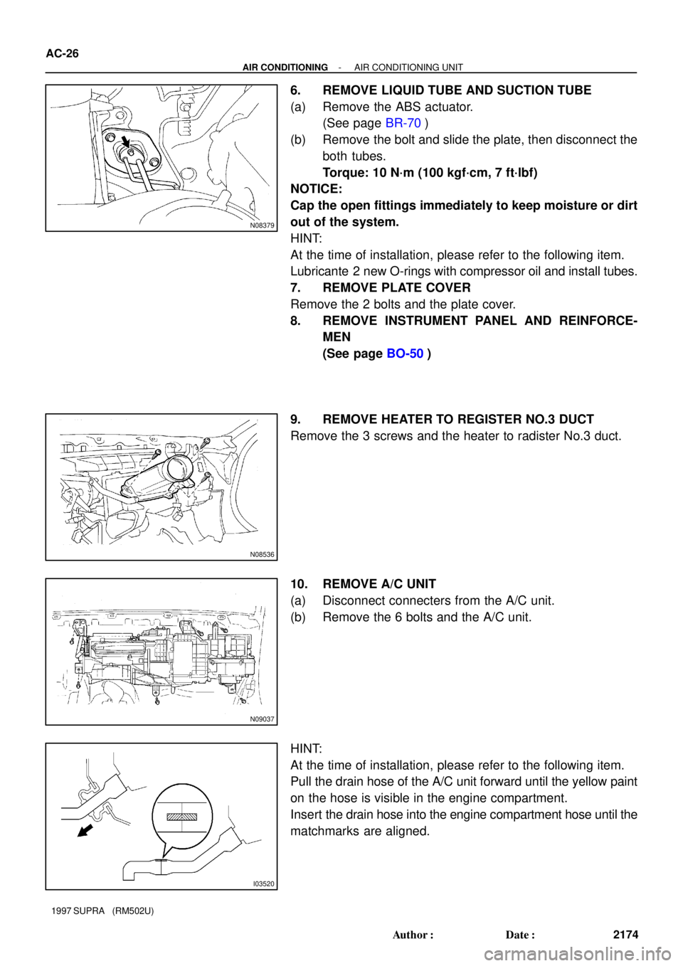
6. REMOVE LIQUID TUBE AND SUCTION TUBE
(a) Remove the ABS actuator.
(See page BR-70)
(b) Remove the bolt and slide the plate, then disconnect the
both tubes.
Torque: 10 N´m (100 kgf´cm, 7 ft´lbf)
NOTICE:
Cap the open fittings immediately to keep moisture or dirt
out of the system.
HINT:
At the time of installation, please refer to the following item.
Lubricante 2 new O-rings with compressor oil and install tubes.
7. REMOVE PLATE COVER
Remove the 2 bolts and the plate cover.
8. REMOVE INSTRUMENT PANEL AND REINFORCE-
MEN
(See page BO-50)
9. REMOVE HEATER TO REGISTER NO.3 DUCT
Remove the 3 screws and the heater to radister No.3 duct.
10. REMOVE A/C UNIT
(a) Disconnect connecters from the A/C unit.
(b) Remove the 6 bolts and the A/C unit.
HINT:
At the time of installation, please refer to the following item.
Pull the drain hose of the A/C unit forward until the yellow paint
on the hose is visible in the engine compartment.
Insert the drain hose into the engine compartment hose until the
matchmarks are aligned.
Page 144 of 1807
AC0R1-01
N19660
- AIR CONDITIONINGWATER VALVE
AC-57
2205 Author�: Date�:
1997 SUPRA (RM502U)
WATER VALVE
REMOVAL
1. DRAIN ENGINE COOLANT FROM RADIATOR
HINT:
It is not to drain out all coolant.
2. REMOVE INSTRUMENT PANEL
(See page BO-54)
3. REMOVE AIR MIX SERVOMOTOR
(See page AC-65)
4. REMOVE WATER VALVE
Remove the 5 screws and water valve.
Page 147 of 1807
AC0R9-01
N08381
N16964
- AIR CONDITIONINGSERVOMOTOR
AC-65
2213 Author�: Date�:
1997 SUPRA (RM502U)
SERVOMOTOR
REMOVAL
1. REMOVE AIR INLET SERVOMOTOR
(a) Remove instrument panel.
(See page BO-54)
(b) Remove air inlet servomotor.
(1) Disconnect the connector.
(2) Disconnect the control link.
(3) Remove the 3 screws and the air inlet servomotor.
2. REMOVE AIR MIX SERVOMOTOR
(a) Remove instrument panel.
(See page BO-54)
(b) Remove air mix servomotor.
(1) Remove the defroster duct.
(2) Remove the 3 screws and the water valve cover.
(3) Disconnect the connector.
(4) Remove the 3 screws and the servomotor then dis-
connect the control link.
Page 148 of 1807
N08404
AC-66
- AIR CONDITIONINGSERVOMOTOR
2214 Author�: Date�:
1997 SUPRA (RM502U)
3. REMOVE AIR OUTLET SERVOMOTOR
(a) Remove instrument panel.
(See page BO-54)
(b) Remove air outlet servomotor.
(1) Disconnect the connector.
(2) Remove the 3 screws and the air outlet servomotor.
Page 149 of 1807
AC0RC-01
N08535
N08693
N08540
- AIR CONDITIONINGSENSOR
AC-69
2217 Author�: Date�:
1997 SUPRA (RM502U)
SENSOR
REMOVAL
1. REMOVE SOLAR SENSOR
(a) Remove instrument panel.
(See page BO-54)
(b) Remove solar sensor.
Disconnect the connector pull the solar sensor upward
from instrument panel.
2. REMOVE ROOM TEMPERATURE SENSOR
(a) Remove center cluster panel.
(See page BO-50)
(b) Remove room temperature sensor.
(1) Disconnect the connector.
(2) Remove the aspirator hose.
(3) Remove the 2 screws and the room temperature
sensor.
3. REMOVE AMBIENT TEMPERATURE SENSOR
Remove ambient temperature sensor.
(1) Remove the ambient temperature sensor from the
bumper reinforcement.
(2) Disconnect the connector.
Page 288 of 1807

BO0R0-01
N08453
BO5232
BO1689
BO-32
- BODYWINDSHIELD
2112 Author�: Date�:
1997 SUPRA (RM502U)
REMOVAL
1. REMOVE THESE PARTS:
(a) Inner rear view mirror
(b) Sun visors and holders
(c) Assist grip (See page BO-61)
HINT:
Tape a screwdriver tip before use.
(d) Front pillar garnishes (See page BO-61)
(e) Wiper arms and blades
(f) Cowl top ventilator louver
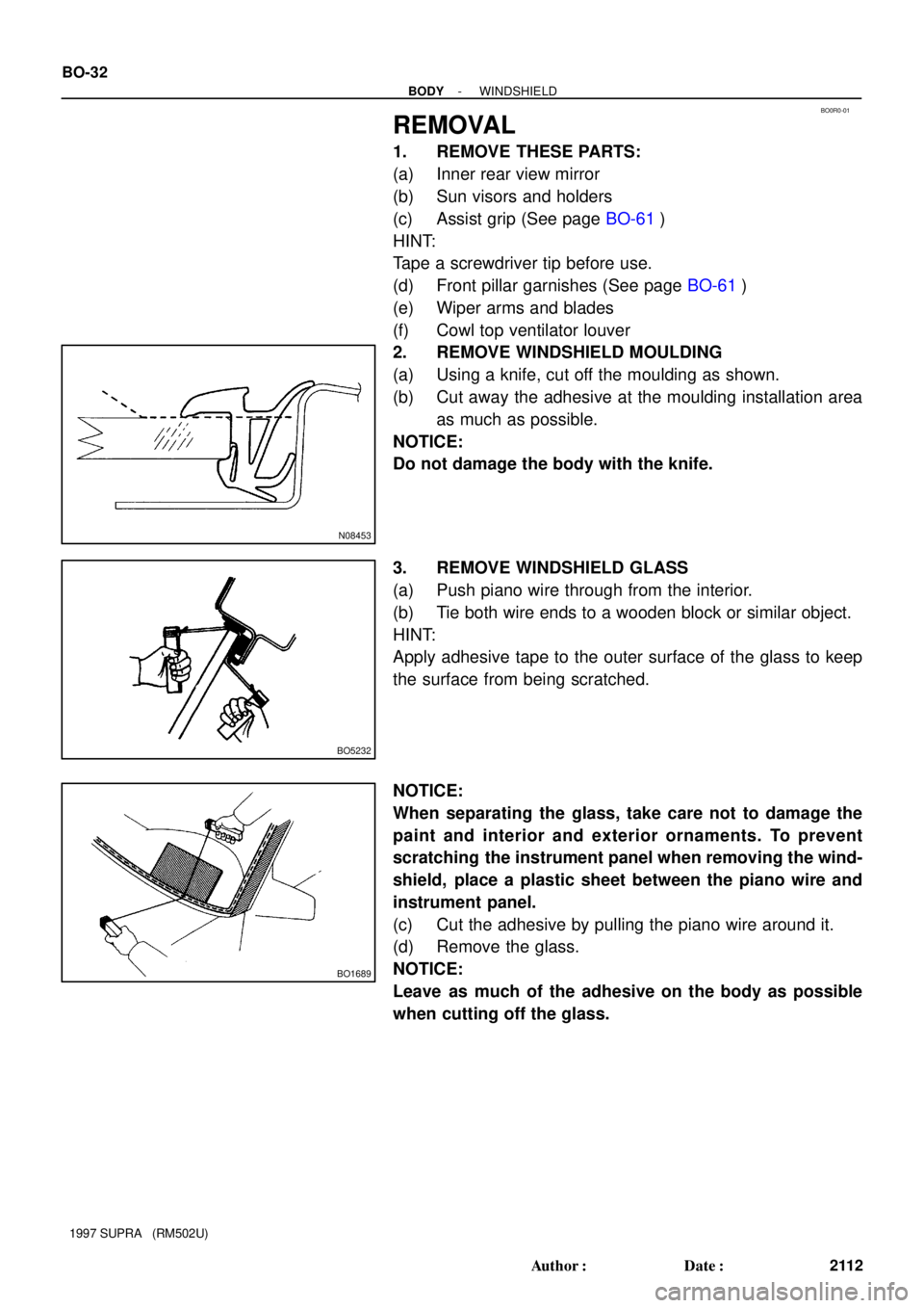
2. REMOVE WINDSHIELD MOULDING
(a) Using a knife, cut off the moulding as shown.
(b) Cut away the adhesive at the moulding installation area
as much as possible.
NOTICE:
Do not damage the body with the knife.
3. REMOVE WINDSHIELD GLASS
(a) Push piano wire through from the interior.
(b) Tie both wire ends to a wooden block or similar object.
HINT:
Apply adhesive tape to the outer surface of the glass to keep
the surface from being scratched.
NOTICE:
When separating the glass, take care not to damage the
paint and interior and exterior ornaments. To prevent
scratching the instrument panel when removing the wind-
shield, place a plastic sheet between the piano wire and
instrument panel.
(c) Cut the adhesive by pulling the piano wire around it.
(d) Remove the glass.
NOTICE:
Leave as much of the adhesive on the body as possible
when cutting off the glass.