Page 70 of 1807

V07469
HEAT METHOD: When the problem seems to occur when the suspect area is heated. 2
NOTICE:
(1) Do not heat to more than 60 °C (140 °F). (Temperature
is limited not to damage the components.)
(2) Do not apply heat directly to parts in the ECU.
3 WATER SPRINKLING METHOD:
NOTICE:
(1) Never sprinkle water directly into the engine
compartment, but indirectly change the temperature and
humidity by applying water spray onto the radiator front
surface.
(2) Never apply water directly onto the electronic
components.
4 OTHER: When a malfunction seems to occur when electrical load is excessive.When the malfunction seems to occur on a rainy day or in a
high-humidity condition. Heat the component that is the likely cause of the malfunction
with a hair dryer or similar object. Check to see if the malfunction
occurs.
Sprinkle water onto the vehicle and check to see if the malfunc-
tion occurs.
Turn on all electrical loads including the heater blower, head
lights, rear window defogger, etc. and check to see if the mal-
function occurs.ON (Service hint)
If a vehicle is subject to water leakage, the leaked water may
contaminate the ECU. When testing a vehicle with a water leak-
age problem, special caution must be taken.
Malfunc-
tion
- INTRODUCTIONHOW TO TROUBLESHOOT ECU CONTROLLED
SYSTEMSIN-23
23 Author�: Date�:
1997 SUPRA (RM502U)
Page 160 of 1807

BE-4
- BODY ELECTRICALBODY ELECTRICAL SYSTEM
1982 Author�: Date�:
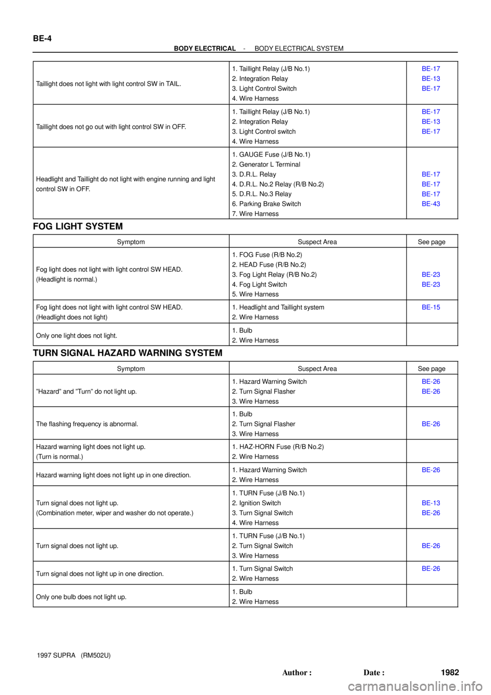
1997 SUPRA (RM502U) Taillight does not light with light control SW in TAIL.
1. Taillight Relay (J/B No.1)
2. Integration Relay
3. Light Control Switch
4. Wire HarnessBE-17
BE-13
BE-17
Taillight does not go out with light control SW in OFF.
1. Taillight Relay (J/B No.1)
2. Integration Relay
3. Light Control switch
4. Wire HarnessBE-17
BE-13
BE-17
Headlight and Taillight do not light with engine running and light
control SW in OFF.
1. GAUGE Fuse (J/B No.1)
2. Generator L Terminal
3. D.R.L. Relay
4. D.R.L. No.2 Relay (R/B No.2)
5. D.R.L. No.3 Relay
6. Parking Brake Switch
7. Wire Harness
BE-17
BE-17
BE-17
BE-43
FOG LIGHT SYSTEM
SymptomSuspect AreaSee page
Fog light does not light with light control SW HEAD.
(Headlight is normal.)
1. FOG Fuse (R/B No.2)
2. HEAD Fuse (R/B No.2)
3. Fog Light Relay (R/B No.2)
4. Fog Light Switch
5. Wire Harness
BE-23
BE-23
Fog light does not light with light control SW HEAD.
(Headlight does not light)1. Headlight and Taillight system
2. Wire HarnessBE-15
Only one light does not light.1. Bulb
2. Wire Harness
TURN SIGNAL HAZARD WARNING SYSTEM
SymptomSuspect AreaSee page
ºHazardº and ºTurnº do not light up.
1. Hazard Warning Switch
2. Turn Signal Flasher
3. Wire HarnessBE-26
BE-26
The flashing frequency is abnormal.
1. Bulb
2. Turn Signal Flasher
3. Wire Harness
BE-26
Hazard warning light does not light up.
(Turn is normal.)1. HAZ-HORN Fuse (R/B No.2)
2. Wire Harness
Hazard warning light does not light up in one direction.1. Hazard Warning Switch
2. Wire HarnessBE-26
Turn signal does not light up.
(Combination meter, wiper and washer do not operate.)
1. TURN Fuse (J/B No.1)
2. Ignition Switch
3. Turn Signal Switch
4. Wire Harness
BE-13
BE-26
Turn signal does not light up.
1. TURN Fuse (J/B No.1)
2. Turn Signal Switch
3. Wire Harness
BE-26
Turn signal does not light up in one direction.1. Turn Signal Switch
2. Wire HarnessBE-26
Only one bulb does not light up.1. Bulb
2. Wire Harness
Page 165 of 1807

- BODY ELECTRICALBODY ELECTRICAL SYSTEM
BE-9
1987 Author�: Date�:
1997 SUPRA (RM502U)
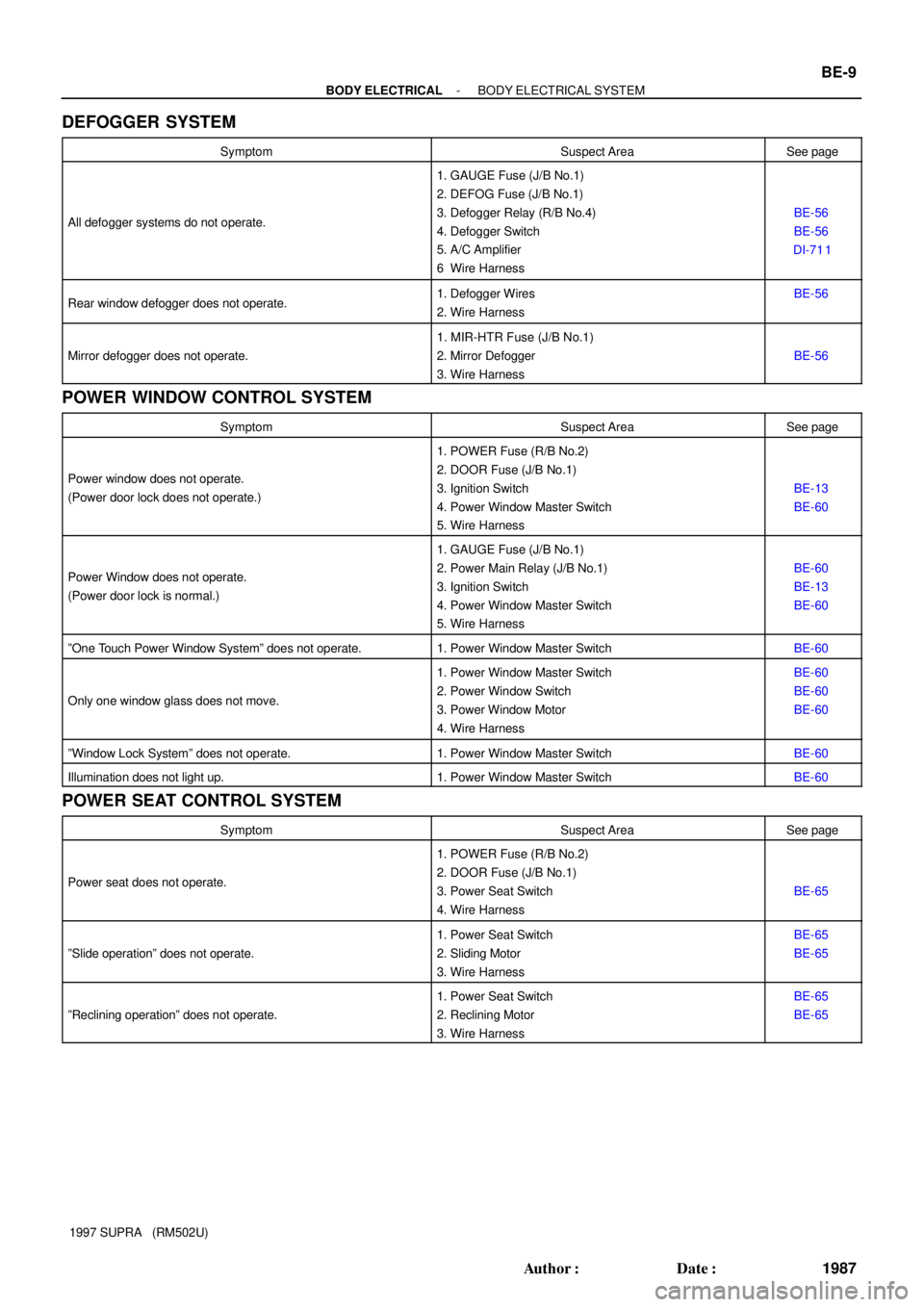
DEFOGGER SYSTEM
SymptomSuspect AreaSee page
All defogger systems do not operate.
1. GAUGE Fuse (J/B No.1)
2. DEFOG Fuse (J/B No.1)
3. Defogger Relay (R/B No.4)
4. Defogger Switch
5. A/C Amplifier
6 Wire Harness
BE-56
BE-56
DI-71 1
Rear window defogger does not operate.1. Defogger Wires
2. Wire HarnessBE-56
Mirror defogger does not operate.
1. MIR-HTR Fuse (J/B No.1)
2. Mirror Defogger
3. Wire Harness
BE-56
POWER WINDOW CONTROL SYSTEM
SymptomSuspect AreaSee page
Power window does not operate.
(Power door lock does not operate.)
1. POWER Fuse (R/B No.2)
2. DOOR Fuse (J/B No.1)
3. Ignition Switch
4. Power Window Master Switch
5. Wire Harness
BE-13
BE-60
Power Window does not operate.
(Power door lock is normal.)
1. GAUGE Fuse (J/B No.1)
2. Power Main Relay (J/B No.1)
3. Ignition Switch
4. Power Window Master Switch
5. Wire Harness
BE-60
BE-13
BE-60
ºOne Touch Power Window Systemº does not operate.1. Power Window Master SwitchBE-60
Only one window glass does not move.
1. Power Window Master Switch
2. Power Window Switch
3. Power Window Motor
4. Wire HarnessBE-60
BE-60
BE-60
ºWindow Lock Systemº does not operate.1. Power Window Master SwitchBE-60
Illumination does not light up.1. Power Window Master SwitchBE-60
POWER SEAT CONTROL SYSTEM
SymptomSuspect AreaSee page
Power seat does not operate.
1. POWER Fuse (R/B No.2)
2. DOOR Fuse (J/B No.1)
3. Power Seat Switch
4. Wire Harness
BE-65
ºSlide operationº does not operate.
1. Power Seat Switch
2. Sliding Motor
3. Wire HarnessBE-65
BE-65
ºReclining operationº does not operate.
1. Power Seat Switch
2. Reclining Motor
3. Wire HarnessBE-65
BE-65
Page 178 of 1807
BE0DU-03
Z18225
Headlights
� Fog Lights
R/B No.2
� Fog Light Relay
� FOG Fuse
� HEAD Fuse
Fog Light Switch BE-22
- BODY ELECTRICALFOG LIGHT SYSTEM
2000 Author�: Date�:
1997 SUPRA (RM502U)
FOG LIGHT SYSTEM
LOCATION
Page 179 of 1807
N19593
ON
Connector ºAº
BE0DV-03
Z07377
- BODY ELECTRICALFOG LIGHT SYSTEM
BE-23
2001 Author�: Date�:
1997 SUPRA (RM502U)
INSPECTION
1. INSPECT FOG LIGHT SWITCH CONTINUITY
Switch positionTester connectionSpecified condition
OFF-No continuity
ONA6 - A7Continuity
If continuity is not as specified, replace the switch.
2. INSPECT FOG LIGHT RELAY CONTINUITY
ConditionTester connectionSpecified condition
Constant1 - 2Continuity
Apply B+ between
terminals 1 and 2.3 - 5Continuity
If continuity is not as specified, replace the relay.
Page 180 of 1807
N19848
Fog Light Adjust Screw
BE0DW-01
BE-24
- BODY ELECTRICALFOG LIGHT SYSTEM
2002 Author�: Date�:
1997 SUPRA (RM502U)
ADJUSTMENT
ADJUST FOG LIGHT AIM
Adjust Screw: Vertical Direction
Page 212 of 1807

BE0ED-01
N08876
Connector B Connector A
10
7
N08877ON
Z05932
BE4029
Tester Probe
Heat Wire
TIn Foil BE-56
- BODY ELECTRICALDEFOGGER SYSTEM
2034 Author�: Date�:
1997 SUPRA (RM502U)
INSPECTION
1. INSPECT DEFOGGER SWITCH OPERATION
(a) Connect the positive (+) lead from the voltmeter to termi-
nal 7 of connector B and the negative (-) lead from volt-
meter to terminal 10 of connector B.
(b) When the switch is off, the voltage should be approx. 12
V.
(c) When the switch is on, check that the indicator light lights
up and that the voltage is less than 1 V.
(d) After 15 minutes, check that the switch is off and the volt-
age is approx. 12 V.
2. INSPECT A/C AMPLIFIER
See page DI-71 1
3. INSPECT DEFOGGER RELAY CONTINUITY
ConditionTester connectionSpecified condition
Constant1 - 2Continuity
Apply B+ between
terminals 1 and 2.3 - 5Continuity
If continuity is not as specified, replace the relay.
4. INSPECT DEFOGGER WIRE
NOTICE:
�When cleaning the glass, use a soft, dry cloth, and
wipe the glass in the direction of the wire. Take care
not to damage the wires.
�Do not use detergents or glass cleaners with abrasive
ingredients.
�When measuring voltage, wind a piece of tin foil
around the top of the negative probe and press the foil
against the wire with your finger, as shown.
Page 572 of 1807

- DIAGNOSTICSENGINE (2JZ-GTE)
DI-157
385 Author�: Date�:
1997 SUPRA (RM502U)
(b) TOYOTA Enhanced Signals
TOYOTA hand-held
tester displayMeasurement ItemNormal Condition*
MISFIRE RPMEngine RPM for first misfire rangeMisfire 0: 0 rpm
MISFIRE LOADEngine load for first misfire rangeMisfire 0: 0 g/r
INJECTORFuel injection time for cylinder No.1Idling: 1.3 ~ 2.7 ms
IAC STEP POSIntake Air Control Valve Step Position Opening position step motor type IAC valveIdling: 10 ~ 50 step
STARTER SIGStarter SignalCranking: ON
CTP SWClosed Throttle Position Switch SignalThrottle fully closed: ON
A/C SIGA/C Switch SignalA/C ON: ON
PNP SWPark / Neutral Position Switch SignalP or N position: ON
ELECTRICAL LOAD SIGElectrical Load SignalDefogger S/W ON: ON
STOP LIGHT SWStop Light Switch SignalStop light switch ON: ON
FC IDLFuel Cut Idle: Fuel cut when throttle valve fully closed, during decelerationFuel cut operating: ON
FC TAUFuel Cut TAU: Fuel cut after between 20 sec. at light loadFuel cut operating: ON
CYL #1
CYL #2
CYL #3
CYL #4
CYL #5
CYL #6
Abnormal revolution variation for each cylinder0%
IGNITIONTotal number of ignitions for every 1,000 revolutions0 ~ 3,0000
EGRT GASEGR Gas Temperature Sensor Value
EGR not operating:
Temperature between intake
air temp. and engine coolant
temp.
FUEL PRES UP VSVFuel Pressure Up VSV SignalHigh temp. restarting: ON
EGR SYSTEMEGR system operating conditionIdling: OFF
FUEL PUMPFuel Pump SignalIdling: ON
A/C MAG CLUTCHA/C Magnetic Clutch SignalA/C ON: ON
EVAP (PURGE) VSVEVAP VSV SignalVSV operating: ON
TURBO BOOST VSVWaste gate valve VSV signalVSV operating: ON
INTK AIR CTL VSVIntake Air Control Valve VSV SignalVSV operating: OFF
EXH GAS CTL VSVExhaust Gas Control Valve VSV SignalVSV operating: OFF
EXH BYPASS VSVExhaust Bypass Valve VSV SignalVSV operating: OFF
TOTAL FT B1Total Fuel Trim Bank 1: Average value for fuel trim system of bank 1Idling: 0.8 ~ 1.2
TOTAL FT B2Total Fuel Trim Bank 2: Average value for fuel trim system of bank 2Idling: 0.8 ~ 1.2
02 LR B1, S1Oxygen Sensor Lean Rich Bank 1, Sensor 1 Response time for oxygen sensor
output to switch from lean to rich.Idling after warmed up:
0 ~ 1,000 m sec.
02 RL B1, S1Oxygen Sensor Rich Lean Bank 1, Sensor 1 Response time for oxygen sensor
output to switch from rich to lean.Idling after warmed up:
0 ~ 1,000 m sec.
*: If no conditions are specifically stated for ºIdlingº, it meas the shift lever is at N or P position, the A/C switch
is OFF and all accessory switches are OFF.