Page 70 of 1807

V07469
HEAT METHOD: When the problem seems to occur when the suspect area is heated. 2
NOTICE:
(1) Do not heat to more than 60 °C (140 °F). (Temperature
is limited not to damage the components.)
(2) Do not apply heat directly to parts in the ECU.
3 WATER SPRINKLING METHOD:
NOTICE:
(1) Never sprinkle water directly into the engine
compartment, but indirectly change the temperature and
humidity by applying water spray onto the radiator front
surface.
(2) Never apply water directly onto the electronic
components.
4 OTHER: When a malfunction seems to occur when electrical load is excessive.When the malfunction seems to occur on a rainy day or in a
high-humidity condition. Heat the component that is the likely cause of the malfunction
with a hair dryer or similar object. Check to see if the malfunction
occurs.
Sprinkle water onto the vehicle and check to see if the malfunc-
tion occurs.
Turn on all electrical loads including the heater blower, head
lights, rear window defogger, etc. and check to see if the mal-
function occurs.ON (Service hint)
If a vehicle is subject to water leakage, the leaked water may
contaminate the ECU. When testing a vehicle with a water leak-
age problem, special caution must be taken.
Malfunc-
tion
- INTRODUCTIONHOW TO TROUBLESHOOT ECU CONTROLLED
SYSTEMSIN-23
23 Author�: Date�:
1997 SUPRA (RM502U)
Page 98 of 1807

36SUPRAÐNEW FEATURES
3) ABS ECU
a. Wheel Speed Control
The ECU constantly receives signals form the 4±speed sensors and a deceleration sensor (2JZ±GTE engine model),
and estimates the speed and deceleration rate of the vehicle by calculating the speed and deceleration rate of each
wheel.
b. Initial Check
An initial check is carried out every time once after the engine has started and the initial vehicle speed exceeds 6 km/h
(4 mph).
c. Self±Diagnosis
If the ABS ECU detects a malfunction in the ABS, the ABS warning light and a master warning lights in the
combination meter will light up and alert the driver that a malfunction has occurred. The ECU will also store the codes
of the malfunctions.
� SUSPENSION
1. General
�The shock absorber of the 2JZ±GTE engine model with manual transmission has been changed from the
mono±tube, gas±filled shock absorber to the twin±tube, gas±filled shock absorber, which is the same type that is
used on the 2JZ±GE engine model.
�The same rubber±integrated ball bushing that is used on the 2JZ±GTE engine model is used for the upper arm
bushing of the rear suspension of the 2JZ±GE engine model.
�The brace rod of the rear subframe has been relocated to realize excellent riding comfort, in addition, this provides
excellent stability, an controllability.
Page 101 of 1807

25 SUPRAÐ NEW FEATURES
NEW FEATURES
� EXTERIOR DESIGN
1. Headlights, Turn Signal Light and Front Bumper
�Multi±reflector type headlights, which contain a multiple paraboloid reflector, have been adopted for the
high±beam headlights. Accordingly, the lens cut in headlights has been significantly decreased to improve the
appearance.
�The shape of the turn signal light lenses has been matched to the curvature of the bumper in order to make them
appear integrated with the bumper. In addition, clear lenses are used, and the parking lights gave been changed from
those enclosed in the headlights to those enclosed in the turn signal lights.
�A bar has been added to the air intake opening in the center of the front bumper.
2. Rear Combination Light
The lens cut of the rear combination lights has been changed from the vertical cut to the lateral cut. In addition, the
rear combination lights have adopted multi±reflectors. As a result of these changes a light design has been achieved
to give a sensor for translucency and depth.
Page 103 of 1807

22SUPRAÐOUTLINE OF NEW FEATURES
SUPRA
OUTLINE NEW FEATURES
The Supra, which represents Toyota's advanced automotive technology, has earned a reputation as a truly luxurious
sports car. The following changes have been made for the 1997 model year.
1. Model Line±Up
�The JZA80L±ALPVZA model has been discontinued.
�The JZA80L±ALFVZA and JZA80L±AJFVZA models have been added.
2. Exterior Design
�The multi±reflector type headlights are adopted.
�The design of the turn signal light, front bumper and rear combination light has been changed.
3. Interior Equipment
The front seats have been changed from the separate±headrest type seats of the '96 model to the integrated headrest
type seats without changing their basic design.
4. 2JZ±GTE Engine
An aluminum radiator core is adopted for weight reduction.
5. Differential
�A differential gear ratio has been changed on he 2JZ±GE engine model.
�A helical gear type torque±sensing LSD is available as an option on the 2JZ±GE engine model and 2JZ±GTE engine
with automatic transmission model.
6. Drive Shaft
An outboard joint of drive shaft has been changed from cross±groove type CVJ (Constant±Velocity Joint) to Rzeppa
type CVJ on the 2JZ±GE engine model.
7. Brakes
�A master cylinder diameter has been changed on the 2JZ±GTE engine model.
�An ABS has been changed to the 2±position solenoid valve type actuator.
Page 162 of 1807

BE-6
- BODY ELECTRICALBODY ELECTRICAL SYSTEM
1984 Author�: Date�:
1997 SUPRA (RM502U)
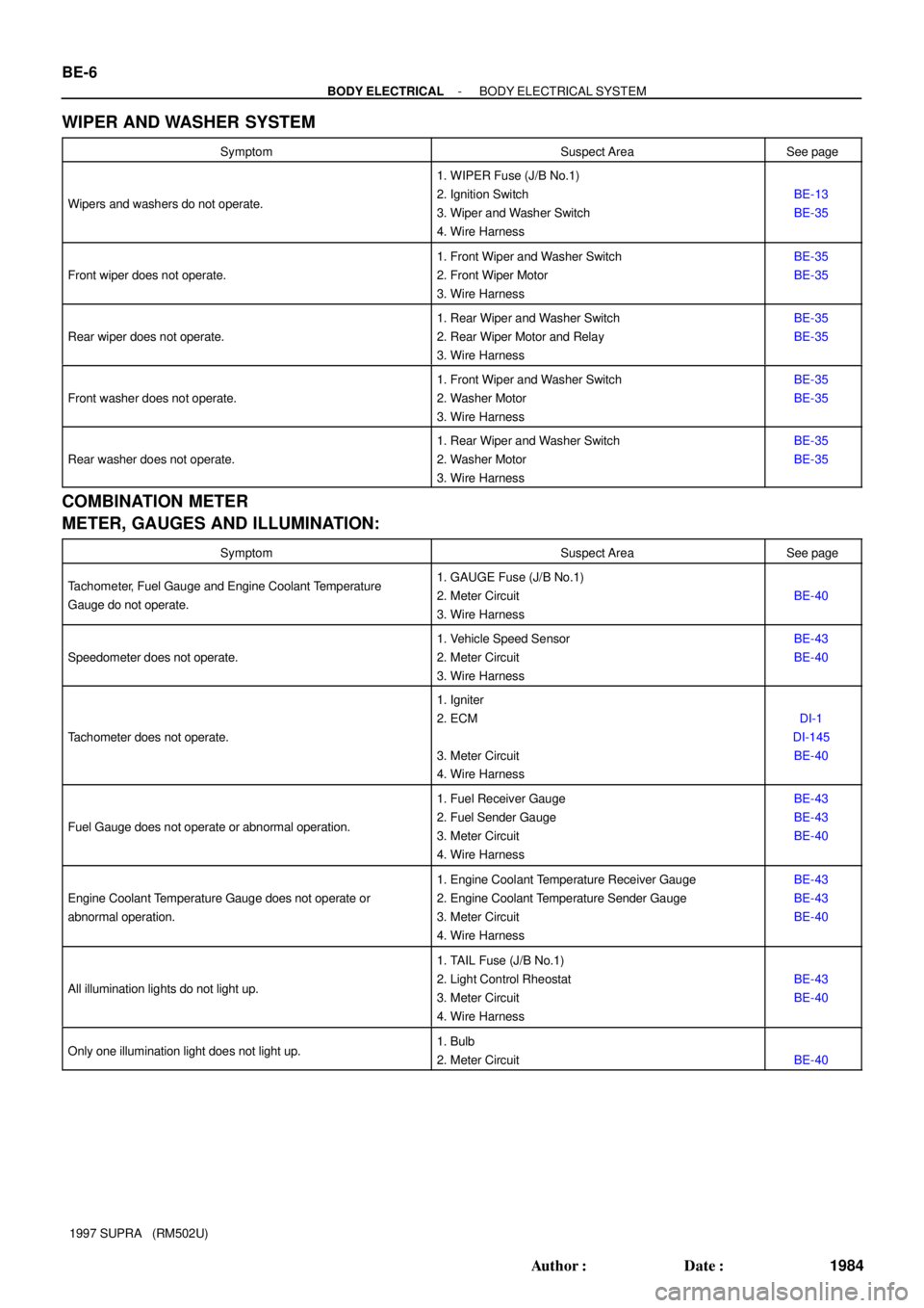
WIPER AND WASHER SYSTEM
SymptomSuspect AreaSee page
Wipers and washers do not operate.
1. WIPER Fuse (J/B No.1)
2. Ignition Switch
3. Wiper and Washer Switch
4. Wire Harness
BE-13
BE-35
Front wiper does not operate.
1. Front Wiper and Washer Switch
2. Front Wiper Motor
3. Wire HarnessBE-35
BE-35
Rear wiper does not operate.
1. Rear Wiper and Washer Switch
2. Rear Wiper Motor and Relay
3. Wire HarnessBE-35
BE-35
Front washer does not operate.
1. Front Wiper and Washer Switch
2. Washer Motor
3. Wire HarnessBE-35
BE-35
Rear washer does not operate.
1. Rear Wiper and Washer Switch
2. Washer Motor
3. Wire HarnessBE-35
BE-35
COMBINATION METER
METER, GAUGES AND ILLUMINATION:
SymptomSuspect AreaSee page
Tachometer, Fuel Gauge and Engine Coolant Temperature
Gauge do not operate.1. GAUGE Fuse (J/B No.1)
2. Meter Circuit
3. Wire Harness
BE-40
Speedometer does not operate.
1. Vehicle Speed Sensor
2. Meter Circuit
3. Wire HarnessBE-43
BE-40
Tachometer does not operate.
1. Igniter
2. ECM
3. Meter Circuit
4. Wire Harness
DI-1
DI-145
BE-40
Fuel Gauge does not operate or abnormal operation.
1. Fuel Receiver Gauge
2. Fuel Sender Gauge
3. Meter Circuit
4. Wire HarnessBE-43
BE-43
BE-40
Engine Coolant Temperature Gauge does not operate or
abnormal operation.
1. Engine Coolant Temperature Receiver Gauge
2. Engine Coolant Temperature Sender Gauge
3. Meter Circuit
4. Wire HarnessBE-43
BE-43
BE-40
All illumination lights do not light up.
1. TAIL Fuse (J/B No.1)
2. Light Control Rheostat
3. Meter Circuit
4. Wire Harness
BE-43
BE-40
Only one illumination light does not light up.1. Bulb
2. Meter Circuit
BE-40
Page 163 of 1807

- BODY ELECTRICALBODY ELECTRICAL SYSTEM
BE-7
1985 Author�: Date�:
1997 SUPRA (RM502U)
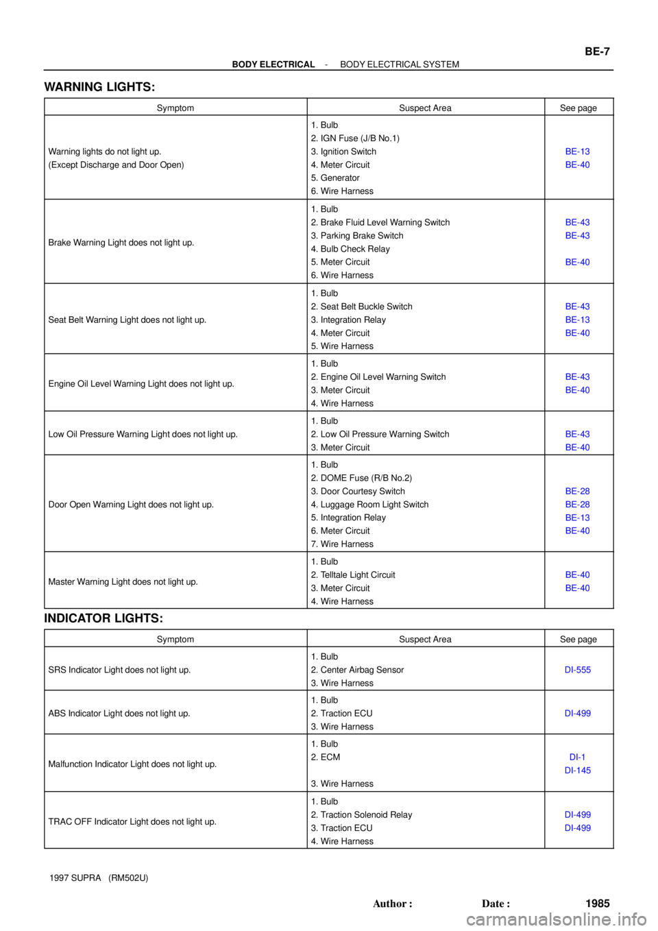
WARNING LIGHTS:
SymptomSuspect AreaSee page
Warning lights do not light up.
(Except Discharge and Door Open)
1. Bulb
2. IGN Fuse (J/B No.1)
3. Ignition Switch
4. Meter Circuit
5. Generator
6. Wire Harness
BE-13
BE-40
Brake Warning Light does not light up.
1. Bulb
2. Brake Fluid Level Warning Switch
3. Parking Brake Switch
4. Bulb Check Relay
5. Meter Circuit
6. Wire Harness
BE-43
BE-43
BE-40
Seat Belt Warning Light does not light up.
1. Bulb
2. Seat Belt Buckle Switch
3. Integration Relay
4. Meter Circuit
5. Wire Harness
BE-43
BE-13
BE-40
Engine Oil Level Warning Light does not light up.
1. Bulb
2. Engine Oil Level Warning Switch
3. Meter Circuit
4. Wire Harness
BE-43
BE-40
Low Oil Pressure Warning Light does not light up.
1. Bulb
2. Low Oil Pressure Warning Switch
3. Meter Circuit
BE-43
BE-40
Door Open Warning Light does not light up.
1. Bulb
2. DOME Fuse (R/B No.2)
3. Door Courtesy Switch
4. Luggage Room Light Switch
5. Integration Relay
6. Meter Circuit
7. Wire Harness
BE-28
BE-28
BE-13
BE-40
Master Warning Light does not light up.
1. Bulb
2. Telltale Light Circuit
3. Meter Circuit
4. Wire Harness
BE-40
BE-40
INDICATOR LIGHTS:
SymptomSuspect AreaSee page
SRS Indicator Light does not light up.
1. Bulb
2. Center Airbag Sensor
3. Wire Harness
DI-555
ABS Indicator Light does not light up.
1. Bulb
2. Traction ECU
3. Wire Harness
DI-499
Malfunction Indicator Light does not light up.
1. Bulb
2. ECM
3. Wire Harness
DI-1
DI-145
TRAC OFF Indicator Light does not light up.
1. Bulb
2. Traction Solenoid Relay
3. Traction ECU
4. Wire Harness
DI-499
DI-499
Page 171 of 1807
Z18223
D.R.L. No.3 Relay*
� Combination Switch
Light Control SwitchD.R.L. Main Relay* Headlights
Front Side MarkerR/B No.2
Headlight Control Relay
Headlight Control Relay
(D.R.L.No.2 Relay)
HEAD (LH) Fuse
HEAD (RH) Fuse
HEAD (LH-LWR) Fuse*
HEAD (LH-UPR) Fuse*
HEAD (RH-UPR) Fuse*
Integration Relay
J/B No.1
Taillight Relay
GAUGE Fuse
TAIL Relay
Rear Side MarkerRear Combination Lights
: Daytime Running Light
: CANADA models D.R.L. Headlight Dimmer SwitchHEAD (LH-LWR) Fuse*
Taillights
* � ��
�
�
�
�
�
�
�
�
�
�
BE0DQ-01
- BODY ELECTRICALHEADLIGHT AND TAILLIGHT SYSTEM
BE-15
1993 Author�: Date�:
1997 SUPRA (RM502U)
HEADLIGHT AND TAILLIGHT SYSTEM
LOCATION
Page 178 of 1807
BE0DU-03
Z18225
Headlights
� Fog Lights
R/B No.2
� Fog Light Relay
� FOG Fuse
� HEAD Fuse
Fog Light Switch BE-22
- BODY ELECTRICALFOG LIGHT SYSTEM
2000 Author�: Date�:
1997 SUPRA (RM502U)
FOG LIGHT SYSTEM
LOCATION