Page 619 of 1807

432 Author�: Date�:
1997 SUPRA (RM502U)
DTC P0300 Random/Multiple Cylinder Misfire Detected
DTC P0301 Cylinder 1 Misfire Detected
DTC P0302 Cylinder 2 Misfire D")
DI-204
- DIAGNOSTICSENGINE (2JZ-GTE)
432 Author�: Date�:
1997 SUPRA (RM502U)
DTC P0300 Random/Multiple Cylinder Misfire Detected
DTC P0301 Cylinder 1 Misfire Detected
DTC P0302 Cylinder 2 Misfire Detected
DTC P0303 Cylinder 3 Misfire Detected
DTC P0304 Cylinder 4 Misfire Detected
DTC P0305 Cylinder 5 Misfire Detected
DTC P0306 Cylinder 6 Misfire Detected
CIRCUIT DESCRIPTION
Misfire: The ECM uses the crankshaft position sensor and camshaft position sensor to monitor changes in
the crankshaft rotation for each cylinder.
The ECM counts the number of times the engine speed change rate indicates that misfire has occurred.
When the misfire rate equals or exceeds the count indicating that the engine condition has deteriorated, the
MIL lights up.
If the misfire rate is high enough and the driving conditions will cause catalyst overheating, the MIL blinks
when misfiring occurs.
DTC No.DTC Detecting ConditionTrouble Area
P0300Misfiring of random cylinders is detected during the any
particular 200 or 1,000 revolutions�Ignition system
�Injector
P0301
P0302
P0303For any particular 200 revolutions of the engine, misfiring is
detected which can cause catalyst overheating (This causes
MIL to blink)
j
�Fuel line pressure
�EGR
�Compression pressure
�
Valve clearance not to specificationP0303
P0304
P0305
P0306For any particular 1,000 revolutions of the engine, misfiring
is detected which causes a deterioration in emission (2 trip
detection logic)
�Valve clearance not to specification
�Valve timing
�Mass air flow meter
�Engine coolant temp. sensor
HINT:
When the 2 or more codes for a misfiring cylinder are recorded repeatedly but no Random Misfire code is
recorded, it indicates that the misfires were detected and recorded at different times.
DI4SZ-01
Page 694 of 1807
S05426
From
BatteryR/B
No.2 2
2A
ALT
R/B
No.2
POWER
22W-L
J/B No.1 210
1B 1ESTOP
WStop Light
Switch
21G-W11
IJ1G-W4
A
STPECM
J/B
No.1 1
101H
1C
Light
Failure
Sensor
To Stop LightG-W
7
- DIAGNOSTICSENGINE (2JZ-GTE)
DI-279
507 Author�: Date�:
1997 SUPRA (RM502U)
DTC P1520 Stop Light Switch Signal Malfunction
Only for A/T
CIRCUIT DESCRIPTION
This signal is used to detect when the brakes have been applied. The STP signal voltage is the same as
the voltage supplied to the stop lights.
The STP signal is used mainly to control the fuel cut-off engine speed. (The fuel cut-off engine speed is
reduced slightly when the vehicle is braking.)
DTC No.DTC Detecting ConditionTrouble Area
P1520
The stop light switch does not turn off even once the vehicle is
driven.
(2 trip detection logic)�Short in stop light switch signal circuit
�Stop light switch
�ECM
WIRING DIAGRAM
DI4TK-01
Page 695 of 1807

DI-280
- DIAGNOSTICSENGINE (2JZ-GTE)
508 Author�: Date�:
1997 SUPRA (RM502U)
INSPECTION PROCEDURE
1 Check operatio")
A00726
ON
ONBrake Pedal
DepressedBrake Pedal
Released
Check Harness A
ECM
A4
STP(+)
DI-280
- DIAGNOSTICSENGINE (2JZ-GTE)
508 Author�: Date�:
1997 SUPRA (RM502U)
INSPECTION PROCEDURE
1 Check operation of stop light.
PREPARATION:
Check if the stop lights go on and off normally when the brake
pedal is operated and released.
NG Check and repair stop light circuit.
OK
2 Check STP signal.
When using TOYOTA hand-held tester:
PREPARATION:
(a) Connect the TOYOTA hand-held tester to the DLC3.
(b) Turn the ignition switch ON and TOYOTA hand-held tes-
ter main switch ON.
CHECK:
Read the STP signal on the TOYOTA hand-held tester.
OK:
Break pedal is depressed: STP ... ON
Break pedal is released: STP ... OFF
When not using TOYOTA hand-held tester:
PREPARATION:
(a) Connect Check Harness A (See page DI-164).
(b) Turn ignition switch ON.
CHECK:
Check voltage between terminal STP of ECM and body ground.
OK:
Brake pedalVoltage
Depressed7.5 - 14 V
ReleasedBelow 1.5 V
OK Check for intermittent problems
(See page DI-147).
NG
Page 773 of 1807
F03341
R/B No.2J/B No.1Stop Light
SwitchABS ECU
125
Light
Failure
Sensor
Stop LightJ/B
No.11
10IH
IC
A18 A22 *1*2
G-WG-W
G-W1
2 W STOP
210
1B 1I W-LPOWER
22 W
2
2A
ALTR/B No.2
B
Battery
NORMAL ABS (2JZ-GE Engine)
SPORT ABS (2JS-GTE Engine)
*1:
*2:
1
DI-482
- DIAGNOSTICSANTI-LOCK BRAKE SYSTEM
710 Author�: Date�:
1997 SUPRA (RM502U)
DTC 49 Stop Light Switch Circuit
CIRCUIT DESCRIPTION
This stop light switch senses whether the brake pedal is depressed or released, and sends a signal to the
ECU.
DTC No.DTC Detecting ConditionTrouble Area
491.2 - 1.7 V of STP voltage is continued for 0.3 sec. or more.�Open in stop light circuit
WIRING DIAGRAM
INSPECTION PROCEDURE
1 Check operation of stop light.
CHECK:
Check that stop light lights up when brake pedal is depressed and turns off when brake pedal is released.
NG Replace stop light bulb.
OK
DI4VI-01
Page 779 of 1807
F03346F03347F03348
2JZ-GE Engine (NORMAL ABS):
2JZ-GTE Engine (SPORT ABS):Battery
ABS Control RelayJ/B No.1
(Motor
Relay)
(Solenoid
Relay)
W-B
1
2
6
A9
4
3
1
4
A9B-R
EA1
6
23 B-R
22
DLC1 Short Pin
L16
IJ1
A18
4
LLL
IF212
L42
ABS
Warning
Light
Y
GAUGE
ABS ECU1J1E
512
25
ABS ActuatorABS ECU
12 V
WA
EA
Battery
R/B No.5
ABS
Solenoid Relay15
5
5555 26
4
5 3
W-B
EA
ABS Actuator
B-R
EA16
23 B-R
Short Pin
DLC1
22L16
IJ1L
L
L11A20WA12 V ABS ECU
ABS
Warning
Light
L4
IF212
2 Y
GAUGE J/B No.1
1J
1E
12 5
ABS & TRAC
ECU DI-488
- DIAGNOSTICSANTI-LOCK BRAKE SYSTEM
716 Author�: Date�:
1997 SUPRA (RM502U)
ABS Warning Light Circuit
CIRCUIT DESCRIPTION
If the ECU detects trouble, it lights the ABS warning light while at the same time prohibiting ABS control. At
this time, the ECU records a DTC in memory.
After removing the short pin of the DLC1, connect terminals Tc and E1 of the DLC1 or DLC2 to make the
ABS warning light to blink and output the DTC.
WIRING DIAGRAM
DI4VL-01
Page 838 of 1807
F03403
Throttle Control ECU
WT
12V
CSW
T16T16
6 10
LG-R LG-R
IF22
TRAC OFF Switch
(TRAC Control Switch)
LG
4 6 W-B
IG IEW-B W-BLG-R
13 OPA DLC2 J/B No.1
GAUGE
1E12
Y
T52TRAC OFF
Indicator
T58
LG-R
- DIAGNOSTICSABS & TRACTION CONTROL SYSTEM
DI-547
775 Author�: Date�:
1997 SUPRA (RM502U)
TRAC OFF Indicator Light, TRAC OFF Switch Circuit
CIRCUIT DESCRIPTION
This is the TRAC control main switch. When the TRAC OFF switch is pushed on, TRAC control goes off and
the TRAC OFF indicator lights up. This indicator blinks for warnings when the trouble occurs and for display-
ing DTC.
WIRING DIAGRAM
INSPECTION PROCEDURE
1 Check DTC.
Check DTC on page DI-501.
YES Repair circuit indicated by the code output.
NO
DI4W9-01
Page 848 of 1807

PRE-CHECK
1. CHECK SRS WARING LIGHT
(a) Turn the ignition swit")
DI4WF-01
R06853
H03184
E1Tc
TcE
1
DLC 1
DLC 2
- DIAGNOSTICSSUPPLEMENTAL RESTRAINT SYSTEM
DI-557
785 Author�: Date�:
1997 SUPRA (RM502U)
PRE-CHECK
1. CHECK SRS WARING LIGHT
(a) Turn the ignition switch to ACC or ON and check that the
SRS warning light lights up.
(b) Check that the SRS warning light goes out after approx.
6 seconds.
HINT:
�When the ignition switch is at ACC or ON and the SRS
warning light remains on or flashes, the airbag sensor as-
sembly has detected a malfunction code.
�If, after approx. 6 seconds have elapsed, the SRS warn-
ing light sometimes lights up or the SRS warning light
lights up even when the ignition switch is OFF, a short in
the SRS warning light circuit can be considered likely.
Proceed to ºSRS warning light system malfunctionº on
page DI-598, DI-600.
2. CHECK DTC (Using diagnosis check wire)
(a) Using diagnosis check wire, check the output of DTC.
(1) Turn the ignition switch to ACC or ON position and
wait approx. 20 seconds.
(2) Using SST, connect the terminals Tc and E
1 of the
DLC1.
HINT:
DTC check and troubleshooting of each DTC can also be done
using DLC2.
SST 09843-18020
NOTICE:
Never make a mistake with the terminal connection posi-
tion as this will cause a malfunction.
Page 854 of 1807
DI4WJ-01
- DIAGNOSTICSSUPPLEMENTAL RESTRAINT SYSTEM
DI-563
791 Author�: Date�:
1997 SUPRA (RM502U)
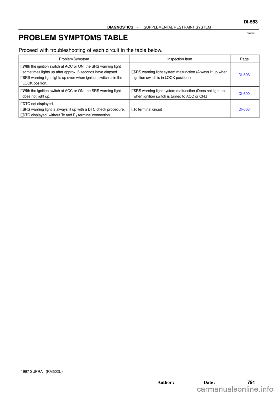
PROBLEM SYMPTOMS TABLE
Proceed with troubleshooting of each circuit in the table below.
Problem SymptomInspection ItemPage
�WIth the ignition switch at ACC or ON, the SRS warning light
sometimes lights up after approx. 6 seconds have elapsed.
�SRS warning light lights up even when ignition switch is in the
LOCK position.
�SRS warning light system malfunction (Always lit up when
ignition switch is in LOCK position.)DI-598
�WIth the ignition switch at ACC or ON, the SRS warning light
does not light up.�SRS warning light system malfunction (Does not light up
when ignition switch is turned to ACC or ON.)DI-600
�DTC not displayed.
�SRS warning light is always lit up with a DTC check procedure.
�DTC displayed without Tc and E
1 terminal connection.
�Tc terminal circuitDI-603


:
2JZ-GTE Engine (SPORT ABS):Battery
ABS Control RelayJ/B No.1
(Motor
Relay)
(Solenoid
Relay)
W-B
1
2
6
A9
4
3
1
4
A9B-R
EA1
6
23 B-R
22
DLC1 Short Pin
L1")

LG
4 6 W-B
IG IEW-B W-BLG-R
13 OPA DLC2 J/B No.1
GAUGE
1E12
Y
T52TRAC OFF
Indicator
T58
LG-R
- D")