Page 365 of 1807
BR0HX-02
R15984
Grease Cap
Front Speed Sensor RotorFront Speed Sensor
� O-ring
Front Fender Splash Shield
� Non-reusable part
- BRAKEFRONT SPEED SENSOR
BR-79
1879 Author�: Date�:
1997 SUPRA (RM502U)
FRONT SPEED SENSOR
COMPONENTS
Page 367 of 1807
BR0I0-02
W02669
Rear Speed Sensor
Rear Speed Sensor Rotor BR-82
- BRAKEREAR SPEED SENSOR
1882 Author�: Date�:
1997 SUPRA (RM502U)
REAR SPEED SENSOR
COMPONENTS
Page 736 of 1807

(b) Using TOYOTA hand-held tester, check the DTC.
(1) Do step (1) - (6) on")
FI6997
TOYOTA
Hand-held
tester
DLC2
- DIAGNOSTICSANTI-LOCK BRAKE SYSTEM
DI-445
673 Author�: Date�:
1997 SUPRA (RM502U)
(b) Using TOYOTA hand-held tester, check the DTC.
(1) Do step (1) - (6) on the previous page.
(2) Hook up the TOYOTA hand- held tester to the
DLC2.
(3) Read the DTC by following the prompts on the tes-
ter screen.
Please refer to the TOYOTA hand-held tester oper-
ator 's manual for farther details.
DTC of speed sensor check function:
Code No.DiagnosisTrouble Area
71Low output voltage of right front speed sensor
�Right front speed sensor
�Sensor installation
�Sensor Rotor
72Low output voltage of left front speed sensor
�Left front speed sensor
�Sensor installation
�Sensor Rotor
73Low output voltage of right rear speed sensor
�Right rear speed sensor
�Sensor installation
�Sensor Rotor
74Low output voltage of left rear speed sensor
�Left rear speed sensor
�Sensor installation
�Sensor Rotor
75Abnormal change in output voltage of right front speed sensor�Right front speed sensor rotor
76Abnormal change in output voltage of left front speed sensor�Left front speed sensor rotor
77Abnormal change in output voltage of right rear speed sensor�Right rear speed sensor rotor
78Abnormal change in output voltage of left rear speed sensor�Left rear speed sensor rotor
79*Deceleration sensor is faulty�Deceleration sensor
�Sensor installation
*: SPORT ABS (2JZ-GTE Engine) only
Page 738 of 1807

DIAGNOSTIC TROUBLE CODE CHART
If a malfunction code is displayed during the DTC check, check the circuit l")
DI4V7-01
- DIAGNOSTICSANTI-LOCK BRAKE SYSTEM
DI-447
675 Author�: Date�:
1997 SUPRA (RM502U)
DIAGNOSTIC TROUBLE CODE CHART
If a malfunction code is displayed during the DTC check, check the circuit listed for that code. For details
of each code, turn to the page referred to under the ºSee pageº for the respective ºDTC No.º in the DTC chart.
HINT:
�Using SST 09843-18020, connect the terminals Tc and E1, and remove the short pin.
�If any abnormality is not found when inspect each inspection parts, inspect the ECU.
DTC No.
(See Page)Detection ItemTrouble Area
11
(DI-453)Open circuit in ABS solenoid relay circuit�ABS solenoid relay
�Open or short in ABS solenoid relay circuit
12
(DI-453)Short circuit in ABS solenoid relay circuit�ABS solenoid relay
�B+ short in ABS solenoid relay circuit
13*2
(DI-460)Open circuit in ABS motor relay circuit�ABS motor relay
�Open or short in ABS motor relay circuit
14
(DI-460)Short circuit in ABS motor relay circuit�ABS motor relay
�B+ short in ABS motor relay circuit
21
(DI-466)Open or short circuit in 2-position solenoid circuit for right front
wheel�ABS actuator
�Open or short in SFRH or SFRR circuit
22
(DI-466)Open or short circuit in 2-position solenoid circuit for left front
wheel�ABS actuator
�Open or short in SFLH or SFLR circuit
23
(DI-466)Open or short circuit in 2-position solenoid circuit for right rear
wheel�ABS actuator
�Open or short in SRH (SRRH) or SRR (SRRR) circuit
24*1
(DI-466)
Open or short circuit in 2-position solenoid circuit for left rear
wheel�ABS actuator
�Open or short in SRLH or SRLR circuit
31*2
(DI-469)Right front wheel speed sensor signal malfunction
32*2
(DI-469)Left front wheel speed sensor signal malfunction�Right front, left front, right rear and left rear speed sensor
O htihd iit33*2
(DI-469)Right rear wheel speed sensor signal malfunction
�Open or short in each speed sensor circuit
�Speed sensor rotor
34*2
(DI-469)Left rear wheel speed sensor signal malfunction
41
(DI-475)Low battery positive voltage
�Battery
�IC regulator
�Open or short in power source circuit
43*1
(DI-479)
Malfunction in deceleration sensor
(constant output)�Deceleration sensor
�Wire harness for deceleration sensor system
44*1
(DI-480)Open or short in deceleration sensor circuit�Deceleration sensor
�Open or short in deceleration sensor circuit
45*1
(DI-479)Malfunction in deceleration sensor�Deceleration sensor
�Wire harness for deceleration sensor system
49
(DI-482)Open circuit in stop light switch circuit�Open in stop light circuit
51*2
(DI-484)
Pump motor is locked
Open in pump motor ground�ABS pump motor
Always
ON
(DI-485)Malfunction in ECU
IG power source circuit�Battery
�IC regulator
�Open or short in power source circuit
Page 740 of 1807
DI4V8-01
W02807
2JZ-GE:
2JZ-GTE:
2JZ-GTE:SPORT AVS (2JZ-GTE Engine):
ABS Control
Relay
ABS Solenoid
Relay
ABS Motor RelayABS ActuatorDeceleration Sensor
ABS Warning Light
ABS ECU
DLC1DLC2
Front Speed Sensor RotorRear Speed SensorRear Speed
Sensor Rotor
Front Speed Sensor
- DIAGNOSTICSANTI-LOCK BRAKE SYSTEM
DI-449
677 Author�: Date�:
1997 SUPRA (RM502U)
PARTS LOCATION
Page 760 of 1807

DTC 31, 32, 33, 34 Speed Senso")
BR3583
BR3582F00010
RotorSpeed Sensor
CoilNSMagnet
To ECU
Low Speed
High Speed
+V
-V
- DIAGNOSTICSANTI-LOCK BRAKE SYSTEM
DI-469
697 Author�: Date�:
1997 SUPRA (RM502U)
DTC 31, 32, 33, 34 Speed Sensor Circuit
CIRCUIT DESCRIPTION
The speed sensor detects the wheel speed and sends the ap-
propriate signals to the ECU. These signals are used to control
the ABS control system. The front and rear rotors each have 48
serrations.
When the rotos rotate, the magnetic field emitted by the perma-
nent magnet in the speed sensor generates an AC voltage.
Since the frequency of this AC voltage changes in direct propor-
tion to the speed of the rotor, the frequency is used by the ECU
to detect the speed of each wheel.
DTC No.DTC Detecting ConditionTrouble Area
31,32,33,34
Detection of any of conditions (1) through (3):
(1) At vehicle speed of 10 km/h (6 mph) or more, pulses are
not input for 15 sec.
(2) Momentary interruption of the vehicle speed sensor signal
occurs at least 7 times in the time between switching the igni-
tion switch ON and switching it OFF.
(3) Abnormal fluctuation of speed sensor signals with the ve-
hicle speed 20 km/h (12 mph) or more.
�Right front, left front, right rear and left rear speed sensor
�Open or short in each speed sensor circuit
�Sensor rotor
HINT:
DTC No.31 is for the right front speed sensor.
DTC No.32 is for the left front speed sensor.
DTC No.33 is for the right rear speed sensor.
DTC No.34 is for the left rear speed sensor.
Fail safe function:
If trouble occurs in the speed sensor circuit, the ECU cuts off current to the ABS solenoid relay and prohibits
ABS control.
DI4VE-01
Page 764 of 1807
F03329
R00948
- DIAGNOSTICSANTI-LOCK BRAKE SYSTEM
DI-473
701 Author�: Date�:
1997 SUPRA (RM502U)
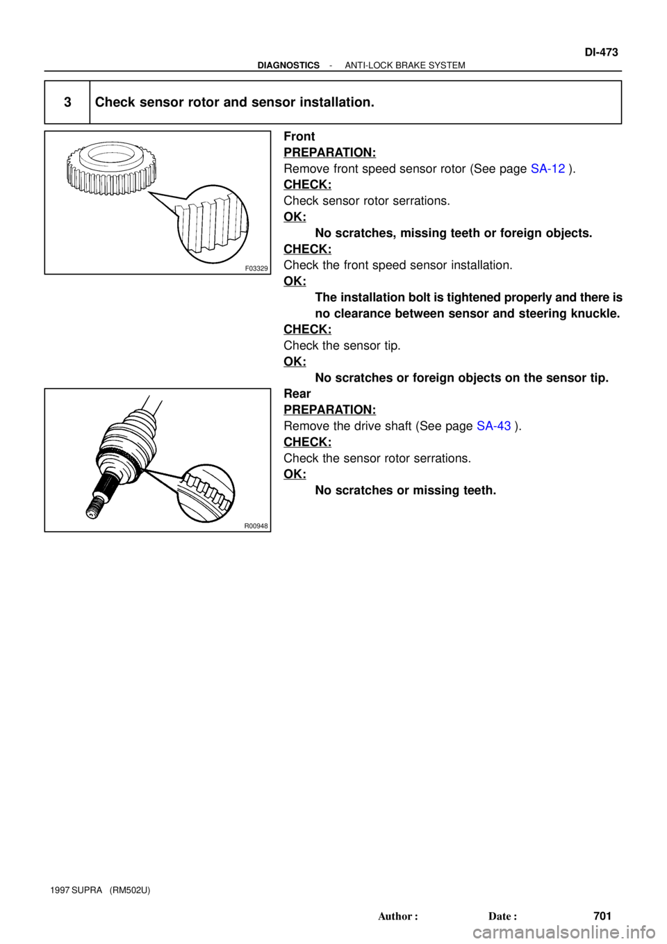
3 Check sensor rotor and sensor installation.
Front
PREPARATION:
Remove front speed sensor rotor (See page SA-12).
CHECK:
Check sensor rotor serrations.
OK:
No scratches, missing teeth or foreign objects.
CHECK:
Check the front speed sensor installation.
OK:
The installation bolt is tightened properly and there is
no clearance between sensor and steering knuckle.
CHECK:
Check the sensor tip.
OK:
No scratches or foreign objects on the sensor tip.
Rear
PREPARATION:
Remove the drive shaft (See page SA-43).
CHECK:
Check the sensor rotor serrations.
OK:
No scratches or missing teeth.
Page 765 of 1807
BR3795OK
NG
DI-474
- DIAGNOSTICSANTI-LOCK BRAKE SYSTEM
702 Author�: Date�:
1997 SUPRA (RM502U)
CHECK:
Check the rear speed sensor installation.
OK:
The installation bolt is tightened properly and there is
no clearance between the sensor and rear axle carri-
er.
CHECK:
Check the sensor tip.
OK:
No scratches or foreign objects on the sensor tip.
NG Replace speed sensor and grease or rotor and
grease.
NOTICE:
Check the speed sensor signal last (See page DI-442).
OK
Check and replace ABS ECU.


:
ABS Control
Relay
ABS Solenoid
Relay
ABS Motor RelayABS ActuatorDeceleration Sensor
ABS Warning Light
ABS ECU
DLC1DLC2
Front Speed")