Page 829 of 1807

BR3583
BR3582F00010
Speed Sensor
High Speed Rotor
+V
-VLow SpeedTo ECU Magnet
CoilNS
DI-538
- DIAGNOSTICSABS & TRACTION CONTROL SYSTEM
766 Author�: Date�:
1997 SUPRA (RM502U)
DTC 61, 62, 63, 64 Speed Sensor Circuit
CIRCUIT DESCRIPTION
The speed sensor detects the wheel speed and sends the ap-
propriate signals to the ECU. These signals are used to control
both the ABS and TRAC control systems. The front and rear ro-
tors each have 48 serrations.
When the rotors rotate, the magnetic field emitted by the perma-
nent magnet in the speed sensor generates an AC voltage.
Since the frequency of this AC voltage changes in direct propor-
tion to the speed of the rotor, the frequency is used by the ECU
to detect the speed of each wheel.
DTC No.DTC Detecting ConditionTrouble Area
61,62,63,64
When the brake switch is OFF, one of the symmetrical wheels'
speed becomes one eight or less of the slowest speed of other
3 wheels continuously for 10 sec. or more.�Right front, left front, right rear and left rear speed sensor
�Wire harness and connector (FRO, FLO, RRO and RLO
circuit)
�Throttle control ECU
HINT:
DTC No.61 is for the right front speed sensor.
DTC No.62 is for the left front speed sensor.
DTC No.63 is for the right rear speed sensor.
DTC No.64 is for the left rear speed sensor.
DI4W6-01
Page 966 of 1807

I02715
Cruise Control Actuator
Magnetic ClutchGND4
C4
C43
LBR-Y
R-L17
IB6
8
IB6W-B
R-L
Battery
STOP10
1I
J/B No.1WCruise Control ECU
13
43
21 S11
S11S11
S11
Stop Light SwitchB-W
G-W G-WC16
C16
C1610
16
To Light Failure SensorGND
L
STP-
- DIAGNOSTICSCRUISE CONTROL SYSTEM
DI-675
903 Author�: Date�:
1997 SUPRA (RM502U)
DTC 12 Magnetic Clutch Circuit
CIRCUIT DESCRIPTION
This circuit turns on the magnetic clutch inside the actuator during cruise control operation according to the
signal from the ECU. If a malfunction occurs in the actuator or speed sensor, etc. during cruise control opera-
tion, the rotor shaft between the motor and control plate is released.
When the brake pedal is depressed, the stoplight switch turns on, supplying electrical power to the stoplight.
Power supply to the magnetic clutch is mechanically cut and the magnetic clutch is turned OFF.
When driving downhill, if the vehicle speed exceeds the set speed by 15 km/h (6 mph) above the set speed,
then cruise control at the set speed is resumed.
DTC No.Detection ItemTrouble Area
12Short in magnetic clutch circuit
Open (0.8 sec.) in magnetic clutch circuit
�Cruise contorl actuator magnetic clutch
�Harness or connector between ECU and magnetic clutch,
magnetic clutch and body ground
�Cruise control ECU
WIRING DIAGRAM
DI4XR-01
Page 1423 of 1807
B03050
MA01H-01
MA-6
- MAINTENANCEBRAKE
43 Author�: Date�:
1997 SUPRA (RM502U)
BRAKE
INSPECTION
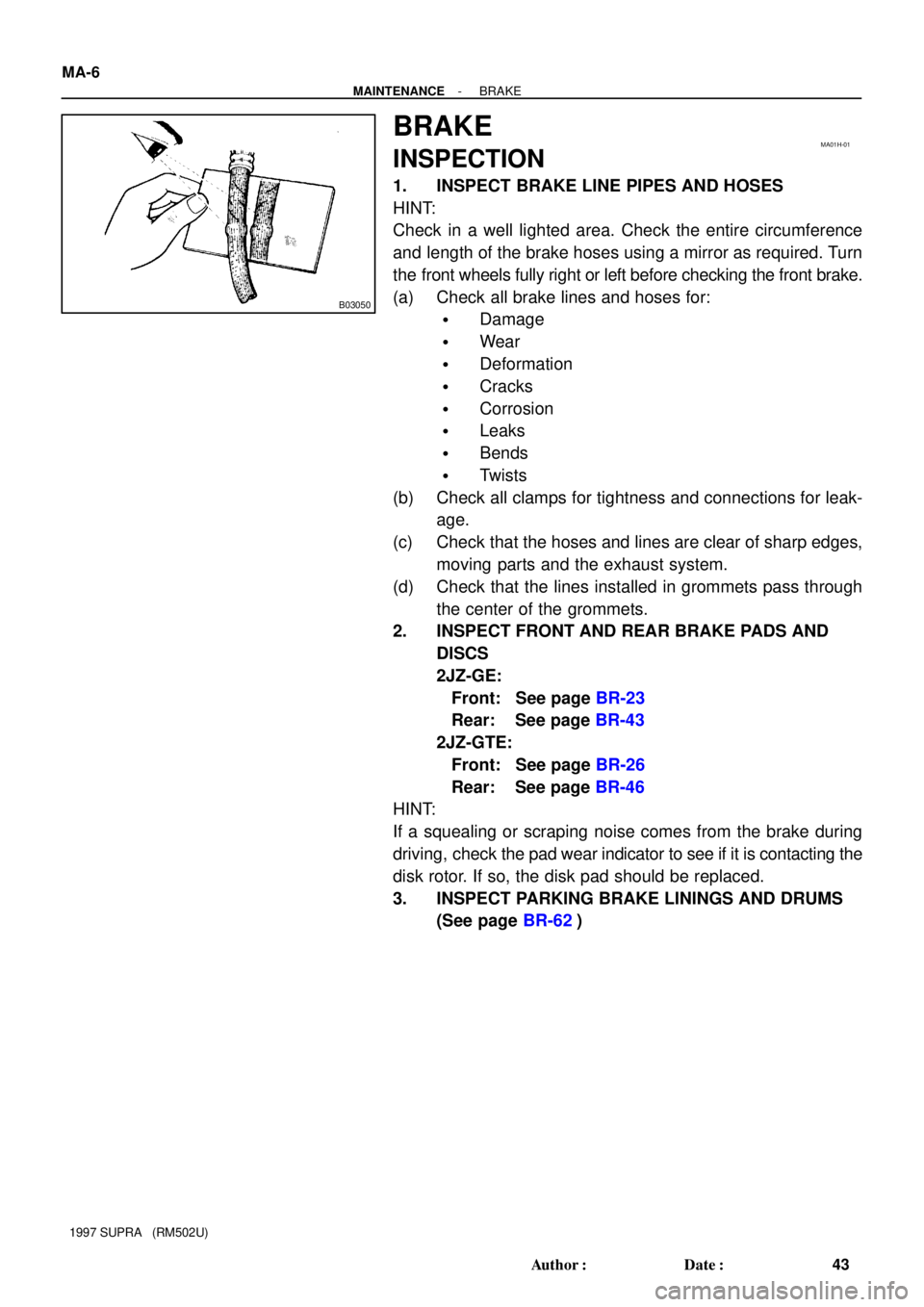
1. INSPECT BRAKE LINE PIPES AND HOSES
HINT:
Check in a well lighted area. Check the entire circumference
and length of the brake hoses using a mirror as required. Turn
the front wheels fully right or left before checking the front brake.
(a) Check all brake lines and hoses for:
�Damage
�Wear
�Deformation
�Cracks
�Corrosion
�Leaks
�Bends
�Twists
(b) Check all clamps for tightness and connections for leak-
age.
(c) Check that the hoses and lines are clear of sharp edges,
moving parts and the exhaust system.
(d) Check that the lines installed in grommets pass through
the center of the grommets.
2. INSPECT FRONT AND REAR BRAKE PADS AND
DISCS
2JZ-GE:
Front: See page BR-23
Rear: See page BR-43
2JZ-GTE:
Front: See page BR-26
Rear: See page BR-46
HINT:
If a squealing or scraping noise comes from the brake during
driving, check the pad wear indicator to see if it is contacting the
disk rotor. If so, the disk pad should be replaced.
3. INSPECT PARKING BRAKE LININGS AND DRUMS
(See page BR-62)
Page 1635 of 1807
SA0OT-02
R11037
Steering
Knuckle with
Axle Hub
Cotter Pin
Brake Caliper
Hub Bolt
Brake Dust Cover
Axle Hub Oil Seal Snap Ring Bearing
Steering Knuckle ABS Speed
Sensor RotorGrease CapTie Rod End ABS Speed Sensor
� Cotter PinClip
Disc
Non-reusable part
- SUSPENSION AND AXLEFRONT AXLE HUB
SA-1 1
1701 Author�: Date�:
1997 SUPRA (RM502U)
FRONT AXLE HUB
COMPONENTS
Page 1638 of 1807

SA0OV-01
R07243
R11077
SST
R11078
SST
SA3584
SST SA-14
- SUSPENSION AND AXLEFRONT AXLE HUB
1704 Author�: Date�:
1997 SUPRA (RM502U)
DISASSEMBLY
1. REMOVE HUB GREASE CAP
Using a screwdriver, remove the grease cap from the steering
knuckle.
2. REMOVE FRONT AXLE HUB LOCK NUT AND ABS
SPEED SENSOR ROTOR
(a) Clamp the axle hub in a soft jaw vise.
HINT:
Close vise until it holds hub bolt. Do not tighten further.
(b) Using a chisel and hammer, loosen the staked part of the
lock nut and remove it.
(c) Remove the sensor rotor.
NOTICE:
Take care not to scratch the serrations of the sensor rotor.
3. REMOVE AXLE HUB FROM STEERING KNUCKLE
(a) Remove the 4 bolts and shift the brake dust cover toward
the axle hub side (outside).
(b) Using SST, remove the axle hub from the steering
knuckle.
SST 09950-40010 (09951-04010, 09952-04010,
09953-04020, 09954-04010, 09955-04030,
09958-04010)
4. REMOVE INNER RACE (OUTSIDE) FROM AXLE HUB
Using SST, remove the inner race from the axle hub.
SST 09950-40010 (09951-04010, 09952-04010,
09953-04020, 09954-04010, 09955-04010,
09958-04010)
5. REMOVE OIL SEAL
Using SST, remove the oil seal from the steering knuckle.
SST 09308-00010
Page 1640 of 1807

SA0OW-02
R15730
SST
R01024
SST
R07351
SST SA-16
- SUSPENSION AND AXLEFRONT AXLE HUB
1706 Author�: Date�:
1997 SUPRA (RM502U)
REASSEMBLY
1. INSTALL BEARING TO STEERING KNUCKLE
(a) Using SST and a press, install a new bearing.
SST 09950-60020 (09951-00720)
NOTICE:
If the inner race and balls come loose from the bearing out-
er race, be sure to install them on the same side as before.
(b) Using snap ring pliers, install the snap ring.
2. INSTALL OIL SEAL
(a) Install the inner race (outside).
(b) Using SST and a hammer, install a new oil seal until it be-
comes flush with the end surface of the steering knuckle.
SST 09608-32010
(c) Coat MP grease to the oil seal lip.
3. INSTALL AXLE HUB TO STEERING KNUCKLE
(a) Install the brake dust cover to the steering knuckle with
the 4 bolts.
Torque: 8.0 N´m (85 kgf´cm, 74 in.´lbf)
(b) Using SST and a press, install the axle hub to steering
knuckle.
SST 09608-32010, 09608-06041
4. INSTALL ABS SPEED SENSOR ROTOR ON AXLE
SHAFT
NOTICE:
Do not scratch the serrations of the sensor rotor.
5. INSTALL AXLE HUB LOCK NUT
(a) Install and torque a new axle hub lock nut.
Torque: 199 N´m (2,030 kgf´cm, 147 ft´lbf)
(b) Using a chisel and hammer, stake the lock nut.
6. INSTALL HUB GREASE CAP
Using a screwdriver and hammer, install the grease cap to the
steering knuckle.
Page 1669 of 1807

SA0PR-02
Z08967
TailpipeCenter Pipe
R07037
Matchmarks
R07024
R06937
- SUSPENSION AND AXLEREAR DRIVE SHAFT
SA-51
1741 Author�: Date�:
1997 SUPRA (RM502U)
REMOVAL
1. REMOVE REAR WHEEL
Torque: 103 N´m (1,050 kgf´cm, 76 ft´lbf)
2. DISCONNECT EXHAUST PIPE SUPPORTS
(a) Remove the 2 exhaust pipe support rings.
(b) Support the exhaust pipe securely.
(c) Remove the 2 exhaust pipe support O-rings.
3. REMOVE COTTER PIN, LOCK CAP AND LOCK NUT
(a) Remove the cotter pin and lock cap.
(b) With applying the brakes, remove the nut.
Torque: 289 N´m (2,950 kgf´cm, 213 ft´lbf)
4. REMOVE LOWER SUSPENSION ARM BRACE
Remove the 4 bolts and lower suspension arm brace.
Torque: 18 N´m (180 kgf´cm, 13 ft´lbf)
5. REMOVE REAR DRIVE SHAFT
(a) Place matchmarks on the drive shaft and side gear shaft.
(b) 2JZ-GE:
Using 8 mm hexagon wrench, remove the 6 hexagon
bolts and 3 washers with applying the brakes.
Torque: 68 N´m (695 kgf´cm, 50 ft´lbf)
(c) 2JZ-GTE:
Using a 10 mm hexagon wrench, remove the 6 hexagon
bolts and 2 washers with applying the brakes.
Torque: 83 N´m (850 kgf´cm, 61 ft´lbf)
(d) Disconnect the inboard joint from the differential side gear
shaft.
(e) Hold the inboard joint side of the drive shaft so that the
outboard joint side does not bend too much.
(f) Using a hammer, lightly tap the end of the drive shaft to
disengage the axle hub and remove the drive shaft.
NOTICE:
�Be careful not to damage the boots and speed sensor
rotor of the drive shaft, and oil seal of the axle hub.
�At the time of installation, make sure the outboard
joint side of the drive shaft does not bend too much.