Page 889 of 1807

W03534
21E 1G
1E1G II1
IF1
IF1
II1
1E 1B3
7
9
4
2
131211 21
2
Battery
1B
5 11 DLC1
Relay Block No.2
ALT
Power
Power
Airbag Sensor
Assembly
Junction Block No.1
Junction Block No.1
SRS Waring Light215
Junction Block No.1
*1: 2JZ-GE Engine
*2: 2JZ-GTE Engine ECU-BTc
ABB (*1)
(*2) B-Y
LA 12
W-RP-B R (*1)
(*2)
P-B
P-B
2
2A2P-B
7
Tc
W-L
ABTc DLC2
R
4
12B-Y
B B
B
B DI-598
- DIAGNOSTICSSUPPLEMENTAL RESTRAINT SYSTEM
826 Author�: Date�:
1997 SUPRA (RM502U)
SRS Warning Light System Malfunction (Always lit up, when igni-
tion switch is in LOCK position.)
CIRCUIT DESCRIPTION
The SRS warning light is located on the combination meter.
When the SRS is normal, the SRS warning light lights up for approx. 6 seconds after the ignition switch is
turned from LOCK position to ACC or ON position, and then turns off automatically.
If there is a malfunction in the SRS, the SRS warning light lights up to inform the driver of the abnormality.
When terminals Tc and E
1 of the DLC1 are connected, the DTC is displayed by the blinking of the SRS warn-
ing light.
WIRING DIAGRAM
DI4WS-01
Page 891 of 1807
 (-)
DI-600
- DIAGNOSTICSSUPPLEMENTAL RESTRAINT SYSTEM
828 Author�: Date�:
1997 SUPRA (RM502U)
SRS Warning Light System Malfunction (Does not light up, when
ignition switch is in turn")
N14677
Fuse
(+) (-)
DI-600
- DIAGNOSTICSSUPPLEMENTAL RESTRAINT SYSTEM
828 Author�: Date�:
1997 SUPRA (RM502U)
SRS Warning Light System Malfunction (Does not light up, when
ignition switch is in turned to ACC or ON.)
CIRCUIT DESCRIPTION
The SRS warning light is located on the combination meter.
When the SRS is normal, the SRS warning light lights up for approx. 6 seconds after the ignition switch is
turned from LOCK position to ACC or ON position, and then turns off automatically.
If there is a malfunction in the SRS, the SRS warning light lights up to inform the driver of the abnormality.
When terminals Tc and E
1 of the DLC1 are connected, the DTC is displayed by the blinking of the SRS warn-
ing light.
WIRING DIAGRAM
Refer to page DI-598 for the WIRING DIAGRAM.
INSPECTION PROCEDURES
1 Check ECU-B Fuse.
PREPARATION:
Remove the ECU-B fuse.
CHECK:
Check the continuity of ECU-B fuse.
OK:
Continuity
HINT:
�Fuse may be burnt out even if it appears to be OK during
visual inspection.
�If fuse is OK, install it.
NG Go to step 5.
OK
2 Preparation (See step 1 on page DI-595).
DI4WT-01
Page 895 of 1807
H03186
ACC
ON
or LOCK
AB0118
R14305AB0119
H00030
ACC
ON
or
(-)DLC 1
(+)Tc E
1
DI-604
- DIAGNOSTICSSUPPLEMENTAL RESTRAINT SYSTEM
832 Author�: Date�:
1997 SUPRA (RM502U)
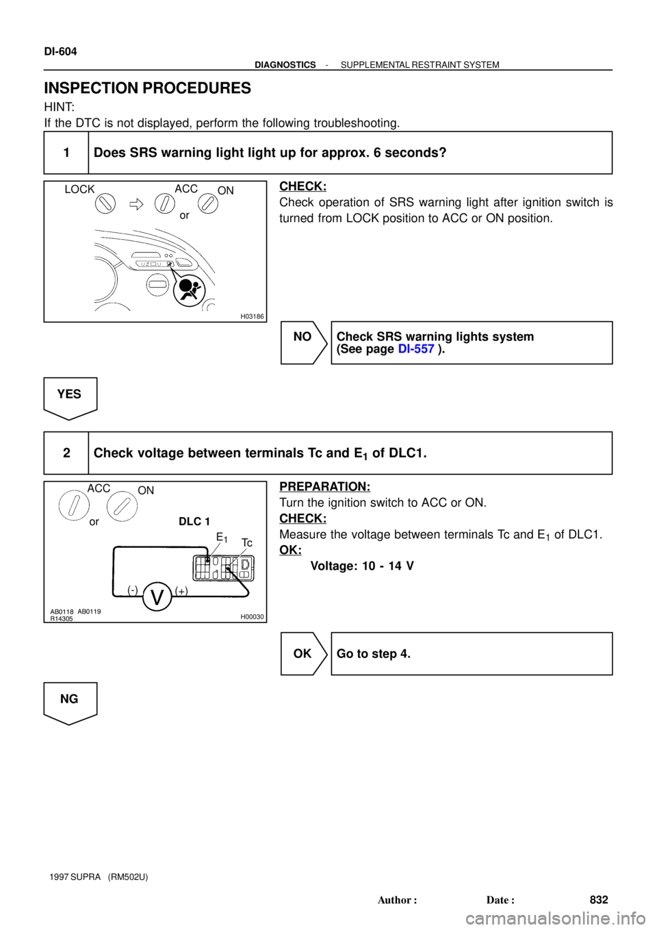
INSPECTION PROCEDURES
HINT:
If the DTC is not displayed, perform the following troubleshooting.
1 Does SRS warning light light up for approx. 6 seconds?
CHECK:
Check operation of SRS warning light after ignition switch is
turned from LOCK position to ACC or ON position.
NO Check SRS warning lights system
(See page DI-557).
YES
2 Check voltage between terminals Tc and E1 of DLC1.
PREPARATION:
Turn the ignition switch to ACC or ON.
CHECK:
Measure the voltage between terminals Tc and E1 of DLC1.
OK:
Voltage: 10 - 14 V
OK Go to step 4.
NG
Page 900 of 1807

DI4WW-01
THEFT DETERRENT SYSTEM Check Sheet
Inspector 's name:
Customer 's Name
Date of VehicleRegistration No.
Registration Year
Frame No.
Odometer Reading / /km
Mile
Weather Conditions
When Problem
Occurred Frequency Problem OccursWeather
Outdoor temperature
/ /
� Constant � Sometimes ( Times per day, month)
� Once only Brought in
� Theft deterrent system cannot be set.
� Indicator light does not flash when the theft deterrent system is set.
(It stays on or does not light at all.)
� Theft deterrent system
does not operate.� When unlocked using the
door lock knob.
� When the engine hood is
opened.
� System cannot be
canceled once set.� When door is unlocked using key or wireless door lock control system.
� When the key is inserted in the ignition key cylinder and turned to ACC or ON
position.
(However, only when the system has never operated)
� When the luggage compartment door is opened with the key.
� System cannot be
canceled during warning
operation.� When door is unlocked using key or wireless door lock control system.
� When the key is inserted in the ignition key cylinder and turned to ACC or ON
position.
� Warning operation starts when the system is set and the door or luggage compartment door is opened with
the key.
� Others.
Date Problem First Occurred
� Fine � Cloudy � Rainy � Snowy
� Various/Others
� Hot � Warm � Cool
� Cold (Approx. 5F ( 5C))
Problem Symptom
Malfunction
� Horns only
� Theft deterrent horn only
� Headlights only
� Taillights only
� Starter cut only
� Door lock operation only
- DIAGNOSTICSTHEFT DETERRENT SYSTEM
DI-609
837 Author�: Date�:
1997 SUPRA (RM502U)
CUSTOMER PROBLEM ANALYSIS CHECK
Page 902 of 1807

4. CHECK OF THE THEFT DETERRENT SYSTEM OPERATION.
HINT:
Ch")
N09348
TOYOTA
hand-held tester
TOYOTA
break-out-boxECU
- DIAGNOSTICSTHEFT DETERRENT SYSTEM
DI-61 1
839 Author�: Date�:
1997 SUPRA (RM502U)
4. CHECK OF THE THEFT DETERRENT SYSTEM OPERATION.
HINT:
Check if the theft deterrent indicator light is blinking.
When any of the following operations (a) or (b) is done, the system sounds the horns as theft deterrent horn
and flashes the headlights and taillights for about one minute to alert. At the same time, the system discon-
nects the starter motor circuit and locks all doors (if all doors are not locked, the system repeats door locking
operation every 2 seconds during the one minute alert time).
(a) Open the engine hood using the engine hood opener lever.
(b) Unlock any of the front or rear doors without key operation.
5. CANCELING OF THE THEFT DETERRENT SYSTEM IN OPERATING CONDITION.
The theft deterrent operation can be cancelled when any of the following conditions is met:
No.ConditionCancelling Operation
1Unlock left or right door with the key.�
2Unlock doors with wireless door lock control system.�
3Insert key into ignition key cylinder and turn it to the ACC or ON position.�*2
4About 1 minute passes after theft deterrent operation begins.Automatic stop*1
*1: In this case, the theft deterrent system resets in about 2 seconds if all doors are closed.
*
2: The alarm will be off, but the engine will not operate. To restart the engine, see No.1
6. ECU TERMINAL VALUES MEASUREMENT USING
TOYOTA BRAKE-OUT-BOX AND TOYOTA HAND-
HElD TESTER
(a) Hook up the TOYOTA brake- out- box and TOYOTA
hand-held tester to the vehicle.
(b) Read the ECU input/output values by following the
prompts on the hand-held tester screen.
HINT:
TOYOTA hand-held tester has a ºSnapshotº function. This re-
cords the measured values and is effective in the diagnosis of
intermittent problems.
Please refer to the TOYOTA hand-held tester/TOYOTA break-
out-box operator's manual for further details.
Page 906 of 1807

PROBLEM SYMPTOMS TABLE
Proceed to the reference page shown in the matrix chart below for each malfunction")
DI4X0-01
- DIAGNOSTICSTHEFT DETERRENT SYSTEM
DI-615
843 Author�: Date�:
1997 SUPRA (RM502U)
PROBLEM SYMPTOMS TABLE
Proceed to the reference page shown in the matrix chart below for each malfunction symptom and trouble-
shoot for each circuit.
HINT:
Troubleshooting of the theft deterrent system is based on the premise that the door lock control system is
operating normally. Accordingly, before troubleshooting the theft deterrent system, first make certain that
the door lock control system is operating normally.
Theft Deterrent System:
Details of ProblemInspecting Circuit *1See page
1. Indicator light circuitDI-617
2. Luggage compartment door key lock and unlock switch
circuitDI-633
The theft deterrent system cannot be set3. Luggage compartment door courtesy switch circuitDI-636
4. Door courtesy switch circuitDI-640
5. Engine hood courtesy switch circuitDI-642
The indicator light does not blink when system is setIndicator light circuitDI-617
�When the system is set
�When the back door is opened by a method other than the key
�The system does not operate
Luggage compartment door courtesy switch circuitDI-636
�When the system is set
�When the engine hood is opened
�The system does not operate
Engine hood courtesy switch circuitDI-642
�While the system is in warning operation
�Horns do not soundHorn relay circuitDI-621
�While the system is in warning operation
�Theft deterrent horn does not soundTheft deterrent horn circuitDI-623
�While the system is in warning operation
�Headlights do not flashHeadlight control relay circuitDI-626
�While the system is in warning operation
�Taillights do not flashTaillight control relay circuitDI-628
�While the system is in warning operation
�The starter cut is not cut offStarter relay circuitDI-619
�When the system is set
�It is not canceled when the ignition key is turned to ACC or ON
position
Ignition switch circuitDI-630
�When the system is set
�It still operates when the back door is opened with the keyLuggage compartment door key lock and unlock switch
circuitDI-633
System is still set even when a rear door is openDoor courtesy switch circuitDI-640
�Even when the system is not set
�Horns soundHorn relay circuitDI-621
�Even when the system is not set
�Theft deterrent horn soundsTheft deterrent horn circuitDI-623
�Even when the system is not set
�Headlights stay onHeadlight control relay circuitDI-626
�Even when the system is not set
�Taillights stay onTaillight control relay circuitDI-628
*1:
If numbers are given to the circuit proceed with troubleshooting in the order indicated by those numbers.
Page 908 of 1807
DI4X1-01
I02537
Indicator Light
(Telltale Light LH)Theft Deterrent and
Door Lock ECU
W-L
W-B9
12
IE
J/B No.1
1
1J
IET13
10 IND
18
- DIAGNOSTICSTHEFT DETERRENT SYSTEM
DI-617
845 Author�: Date�:
1997 SUPRA (RM502U)
CIRCUIT INSPECTION
Indicator Light Circuit
CIRCUIT DESCRIPTION
When the theft deterrent system is preparing to set, this circuit lights up the indicator light. When the system
has been set, it continually turns the indicator light on for 1 second and turns it off for 1 second, thus blinking
the indicator light.
WIRING DIAGRAM
Page 917 of 1807
*1
HEAD
(LH-L WR)*2HEAD R/B No.2
FL MAIN
Light Control
Switch
R/B No.2
HEAD
(RH)*1
HEAD
(RH-L WR)*2R-")
I02543
Theft Deterrent and
Door Lock ECU
*1: USA Models
*2: CANADA Models BatteryR/B No.2
HEAD
(LH)*1
HEAD
(LH-L WR)*2HEAD R/B No.2
FL MAIN
Light Control
Switch
R/B No.2
HEAD
(RH)*1
HEAD
(RH-L WR)*2R-Y R-Y R-Y R-Y
R-G R-B
W-B
W-B BRR 2
2
2
22
22
2
11 1 1
4
23
10 16 13
IB2
IF2 2A
EA Headlight Relay
T13
DI-626
- DIAGNOSTICSTHEFT DETERRENT SYSTEM
854 Author�: Date�:
1997 SUPRA (RM502U)
Headlight Control Relay Circuit
CIRCUIT DESCRIPTION
When the theft deterrent system is activated, it causes the Tr in the ECU to switch on and off at approximately
0.2 sec. intervals. This switches the headlight control relay on and off, thus flashing the headlights (See the
wiring diagram below).
In this condition, if any of the following operations is done, the Tr in the ECU goes off and the headlight control
relay switches off, thus stopping the headlights flashing:
(1) The front LH or RH door is unlocked with a key.
(2) The ignition switch is turned to the ACC or ON position.
(3) Approximately 1 minute elapses.
WIRING DIAGRAM
DI4X5-01