Page 350 of 1807
BR0HF-01
R07153
R07154
- BRAKEREAR BRAKE CALIPER (2JZ-GTE)
BR-55
1855 Author�: Date�:
1997 SUPRA (RM502U)
REMOVAL
1. REMOVE REAR WHEEL
2. DISCONNECT FLEXIBLE HOSE
(a) Remove the union bolt and 2 gaskets from the caliper,
then disconnect the flexible hose from the caliper.
Torque: 30 N´m (310 kgf´cm, 22 ft´lbf)
HINT:
At the time of installation, please refer to the following item.
Install the flexible hose lock securely in the lock hole in the cali-
per.
(b) Use a container to catch the brake fluid.
3. REMOVE CALIPER
Remove the 2 mounting bolts and caliper.
Torque: 104 N´m (1,065 kgf´cm, 77 ft´lbf)
4. REMOVE THESE PARTS
(a) Clip
(b) 2 pins
(c) Anti-rattle spring
(d) 2 pads
(e) 4 anti-squeal shims
Page 354 of 1807

BR0HL-01
R07154
BR5358
Matchmarks
BR5349
BR5331
BR3564
- BRAKEPARKING BRAKE
BR-61
1861 Author�: Date�:
1997 SUPRA (RM502U)
DISASSEMBLY
1. REMOVE REAR WHEEL
2. REMOVE REAR DISC BRAKE ASSEMBLY
(a) Remove the 2 mounting bolts and remove the disc brake
assembly.
Torque: 104 N´m (1,065 kgf´cm, 77 ft´lbf)
(b) Suspend the disc brake securely and so the hose is not
stretched.
3. REMOVE DISC
(a) Place matchmarks on the disc and rear axle hub.
(b) Remove the disc.
HINT:
�If the disc cannot be removed easily, return the shoe ad-
juster until the disc turns freely.
�If there are no matchmarks, temporarily install the disc,
then measure the disc runout and install the disc in the
position (See step 4 on page BR-51).
4. REMOVE SHOE RETURN SPRINGS
Using needle-nose pliers, remove the 2 shoe return springs.
5. REMOVE SHOE STRUT WITH SPRING
6. REMOVE FRONT SHOE, ADJUSTER AND TENSION
SPRING
(a) Slide out the front shoe and remove the shoe adjuster.
(b) Disconnect the tension spring and remove the front shoe.
7. REMOVE REAR SHOE
(a) Slide out the rear shoe.
(b) Remove the tension spring from the rear shoe.
(c) Disconnect the parking brake cable from the parking
brake shoe lever.
(d) Remove the shoe hold-down spring cups, springs and
pins.
Page 360 of 1807

W03289
W03290
W03291
W03292
- BRAKEABS ACTUATOR (2JZ-GTE)
BR-73
1873 Author�: Date�:
1997 SUPRA (RM502U)
(c) Place the ºSHEET Nº (SST) on the actuator checker.
SST 09990-00410
4. INSPECT BRAKE ACTUATOR OPERATION OF
FRONT LH WHEEL
(a) Start the engine, and run it at idle.
(b) Turn the selector switch of the actuator checker to
ºFRONT RHº position.
(c) Push and hold in the MOTOR switch for a few seconds.
Make sure that you can hear the motor running.
(d) Depress the brake pedal and hold it for about 15 seconds,
and check that the pedal does not go down.
(e) With your foot still applying onto the brake pedal, push
MOTOR switch and check that the brake pedal does not
pulsate.
(f) Depress the brake pedal and hold it. As you hold the ped-
al down, push and hold in the MAIN push switch for a few
seconds. Check that the pedal does not go down.
NOTICE:
Do not keep pushing the MAIN push switch more than 10
seconds.
(g) With your foot still applying onto the brake pedal, release
the MAIN push switch and check that the pedal goes
down.
(h) With your foot still applying onto the brake pedal, push the
MOTOR switch and check that the brake pedal returns.
(i) Release the brake pedal.
5. INSPECT FOR OTHER WHEEL
(a) Turn the selector switch to the ºREAR LHº position, and
inspect the ºREAR LHº wheel.
(b) Repeating (c) to (i) in the step 4, check the actuator opera-
tion similarly.
Page 361 of 1807
BR-74
- BRAKEABS ACTUATOR (2JZ-GTE)
1874 Author�: Date�:
1997 SUPRA (RM502U)
(c) Similarly, inspect the ºREAR RHº and ºFRONT RHº wheel.
HINT:
When inspecting the ºFRONT RHº wheel, push the FRONT LH
switch instead of the MAIN push switch. This makes it possible
to inspect wherever the selector switch position indicates.
6. PUSH MOTOR SWITCH
(a) Push and hold in the MOTOR switch for a few seconds.
(b) Stop the engine.
7. DISCONNECT ACTUATOR CHECKER (SST) FROM
ACTUATOR
(a) Disconnect the actuator checker (SST) and sub-wire har-
nesses (SST) from the actuator.
SST 09990-00150, 09990-00250, 09990-00300,
09990-00360, 09990-00410
(b) Connect the 2 actuator connectors.
(c) Clear the DTC (See page DI-442).
Page 371 of 1807

mm in.
50.20Normal Roof:
Sport Roof:
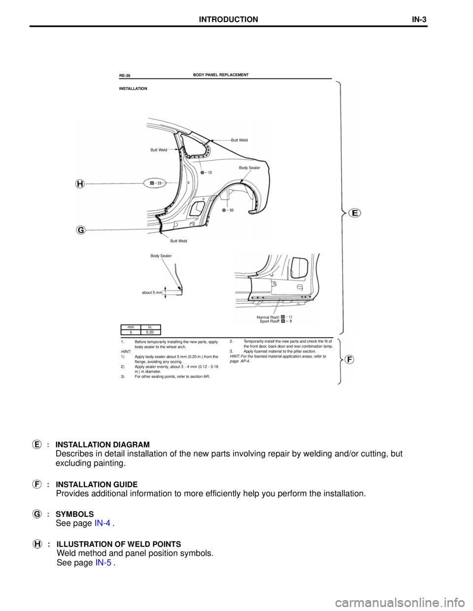
1. Before temporarily installing the new parts, apply
body sealer to the wheel arch.
HINT:1) Apply body sealer about 5 mm (0.20 in.) from the
flange, avoiding any oozing.
2) Apply sealer evenly, about 3 - 4 mm (0.12 - 0.16
in.) in diameter.
3) For other sealing points, refer to section AR.BODY PANEL REPLACEMENT
RE-36
INSTALLATION
Butt Weld
Butt Weld
Body Sealer
Butt Weld
Body Sealer
about 5 mm
2. Temporarily install the new parts and check the fit of
the front door, back door and rear combination lamp.
3. Apply foamed material to the pillar section.HINT: For the foamed material application areas, refer to
page AP-4.
INSTALLATION DIAGRAM
Describes in detail installation of the new parts involving repair by welding and/or cutting, but
excluding painting.
INSTALLATION GUIDE
Provides additional information to more efficiently help you perform the installation.
SYMBOLS
See page IN-4.
ILLUSTRATION OF WELD POINTS
Weld method and panel position symbols.
See page IN-5.
INTRODUCTIONIN-3
Page 374 of 1807

Steering Wheel Pad
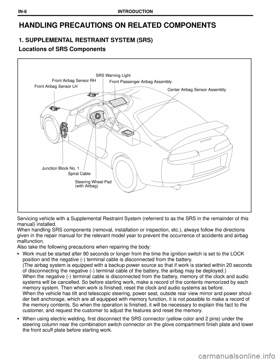
(with Airbag) Junction Block No. 1Center Airbag Sensor Assembly Front Airbag Sensor LHFront Passenger Airbag Assembly Front Airbag Sensor RHSRS Warning Light
Spiral Cable
Locations of SRS Components
HANDLING PRECAUTIONS ON RELATED COMPONENTS
1. SUPPLEMENTAL RESTRAINT SYSTEM (SRS)
Servicing vehicle with a Supplemental Restraint System (referrerd to as the SRS in the remainder of this
manual) installed.
When handling SRS components (removal, installation or inspection, etc.), always follow the directions
given in the repair manual for the relevant model year to prevent the occurrence of accidents and airbag
malfunction.
Also take the following precautions when repairing the body:
�Work must be started after 90 seconds or longer from the time the ignition switch is set to the LOCK
position and the negative (-) terminal cable is disconnected from the battery.
(The airbag system is equipped with a backup power source so that if work is started within 20 seconds
of disconnecting the negative (-) terminal cable of the battery, the airbag may be deployed.)
When the negative (-) terminal cable is disconnected from the battery, memory of the clock and audio
systems will be cancelled. So before starting work, make a record of the contents memorized by each
memory system. Then when work is finished, reset the clock and audio systems as before.
When the vehicle has tilt and telescopic steering, power seat, outside rear view mirror and power shoul-
der belt anchorage, which are all equipped with memory function, it is not possible to make a record of
the memory contents. So when the operation is finished, it will be necessary to explain this fact to the
customer, and request the customer to adjust the features and reset the memory.
�When using electric welding, first disconnect the SRS connector (yellow color and 2 pins) under the
steering column near the combination switch connector on the glove compartment finish plate and lower
the front scuff plate before starting work.
INTRODUCTIONIN-6
Page 375 of 1807

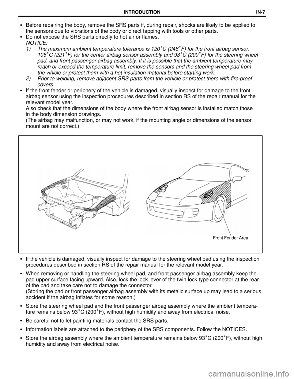
Front Fender Area
�Before repairing the body, remove the SRS parts if, during repair, shocks are likely to be applied to
the sensors due to vibrations of the body or direct tapping with tools or other parts.
�Do not expose the SRS parts directly to hot air or flames.
NOTICE:
1) The maximum ambient temperature tolerance is 120
°C (248°F) for the front airbag sensor,
105
°C (221°F) for the center airbag sensor assembly and 93°C (200°F) for the steering wheel
pad, and front passenger airbag assembly. If it is possible that the ambient temperature may
reach or exceed the temperature limit, remove the sensors and the steering wheel pad from
the vihicle or protect them with a hot insulation material before starting work.
2) Prior to welding, remove adjacent SRS parts from the vehicle or protect there with fire-proof
covers.
�If the front fender or periphery of the vehicle is damaged, visually inspect for damage to the front
airbag sensor using the inspection procedures described in section RS of the repair manual for the
relevant model year.
Also check that the dimensions of the body where the front airbag sensor is installed match those
in the body dimension drawings.
(The airbag may malfunction, or may not work, if the mounting angle or dimensions of the sensor
mount are not correct.)
�If the vehicle is damaged, visually inspect for damage to the steering wheel pad using the inspection
procedures described in section RS of the repair manual for the relevant model year.
�When removing or handling the steering wheel pad, and front passenger airbag assembly keep the
pad upper surface facing upward. Also, lock the lock lever of the twin lock type connector at the rear
of the pad and take care not to damage the connector.
(Storing the pad or front passenger airbag assembly with its metalic surface up may lead to a serious
accident if the airbag inflates for some reason.)
�Store the steering wheel pad and the front passenger airbag assembly where the ambient tempera-
ture remains below 93°C (200°F), without high humidity and away from electrical noise.
�Be careful not to let painting materials contact the SRS parts.
�Information labels are attached to the periphery of the SRS components. Follow the NOTICES.
�Store the airbag assembly where the ambient temperature remains below 93°C (200°F), without high
humidity and away from electrical noise.
INTRODUCTIONIN-7
Page 376 of 1807

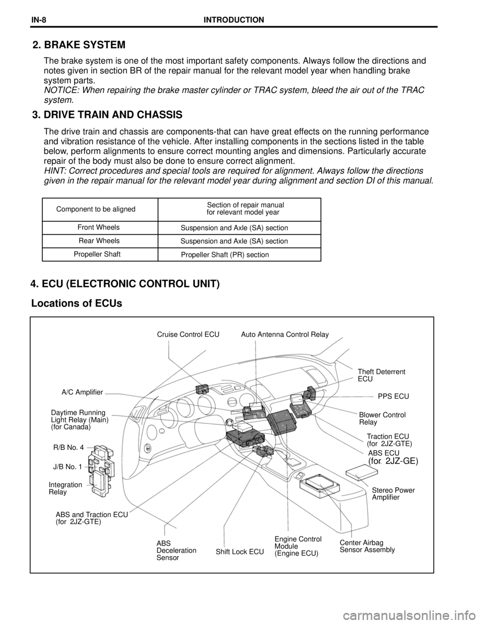
Shift Lock ECUEngine Control
Module
(Engine ECU)Center Airbag
Sensor Assembly ABS
Deceleration
Sensor ABS and Traction ECU
(for 2JZ-GTE)Stereo Power
Amplifier Integration
RelayJ/B No. 1Traction ECU
(for 2JZ-GTE)
R/B No. 4 Daytime Running
Light Relay (Main)
(for Canada)Blower Control
RelayPPS ECU A/C AmplifierTheft Deterrent
ECU Cruise Control ECU Auto Antenna Control Relay
ABS ECU
(for 2JZ-GE)
Component to be alignedSection of repair manual
for relevant model year
Front Wheels
Suspension and Axle (SA) section
Rear Wheels
Suspension and Axle (SA) section
Propeller Shaft
Propeller Shaft (PR) section
3. DRIVE TRAIN AND CHASSIS2. BRAKE SYSTEM
The brake system is one of the most important safety components. Always follow the directions and
notes given in section BR of the repair manual for the relevant model year when handling brake
system parts.
NOTICE: When repairing the brake master cylinder or TRAC system, bleed the air out of the TRAC
system.
The drive train and chassis are components-that can have great effects on the running performance
and vibration resistance of the vehicle. After installing components in the sections listed in the table
below, perform alignments to ensure correct mounting angles and dimensions. Particularly accurate
repair of the body must also be done to ensure correct alignment.
HINT: Correct procedures and special tools are required for alignment. Always follow the directions
given in the repair manual for the relevant model year during alignment and section DI of this manual.
4. ECU (ELECTRONIC CONTROL UNIT)
Locations of ECUs
INTRODUCTIONIN-8