Page 158 of 1807

PROBLEM SYMPTOMS TABLE
IGNITION SWITCH AND KEY UNLOCK WARNING SWITCH
SymptomSuspect AreaSee page
Igniti")
BE0DM-02
BE-2
- BODY ELECTRICALBODY ELECTRICAL SYSTEM
1980 Author�: Date�:
1997 SUPRA (RM502U)
PROBLEM SYMPTOMS TABLE
IGNITION SWITCH AND KEY UNLOCK WARNING SWITCH
SymptomSuspect AreaSee page
Ignition switch is not set to each position.1. Ignition SwitchBE-13
ºKey unlock warning systemº does not operate.
1. GAUGE Fuse (J/B No.1)
2. Key Unlock Warning Switch
3. Door Courtesy Switch
4. Wire Harness
BE-13
BE-28
USA:
HEADLIGHT AND TAILLIGHT SYSTEM
SymptomSuspect AreaSee page
Headlight does not light. (Taillight is normal)
1. Headlight Bulb
2. HEAD (LH, RH) Fuse (R/B No.2)
3. Headlight Control Relay (R/B No.2)
4. Integration Relay
5. Headlight Dimmer Switch
6. Light Control Switch
7. Wire Harness
BE-17
BE-13
BE-17
BE-17
Headlight does not light. (Taillight does not light up)
1. Headlight Bulb
2. Integration Relay
3. Light Control Switch
4. Wire Harness
BE-13
BE-17
Only one side light does not light.
1. Headlight Bulb
2. HEAD (LH, RH) Fuse (R/B No.2)
3. Wire Harness
ºLo-Beamº does not light.1. Headlight Dimmer Switch
2. Wire HarnessBE-17
ºHi-Beamº does not light.1. Headlight Dimmer Switch
2. Wire HarnessBE-17
ºFlashº does not light.1. Headlight Dimmer Switch
2. Wire HarnessBE-17
Page 161 of 1807

INTERIOR LIGHT SYSTEM
SymptomSuspect AreaSee page
Only one light does not light up.1. Bulb
2. Wire Harness
Inter")
- BODY ELECTRICALBODY ELECTRICAL SYSTEM
BE-5
1983 Author�: Date�:
1997 SUPRA (RM502U)
INTERIOR LIGHT SYSTEM
SymptomSuspect AreaSee page
Only one light does not light up.1. Bulb
2. Wire Harness
Interior light does not light up (All).
1. DOME Fuse (R/B No.2)
2. Integration Relay
3. Wire Harness
BE-28
ºIlluminated Entry Systemº does not operate.
1. Integration Relay
2. Door Courtesy Switch
3. Door Key Lock and Unlock Switch
4. Door Unlock Detection Switch
5. Wire HarnessBE-28
BE-28
DI-656
DI-638
Front personal light does not light up.
1. Bulb
2. Front Personal Light
3. Wire Harness
BE-28
Luggage room light does not light up.1. Bulb
2. Luggage Room Light Switch
BE-28
BACK-UP LIGHT SYSTEM
SymptomSuspect AreaSee page
Back Up Light does not light up.
1. Bulb
2. GAUGE Fuse (J/B No.1)
3. Ignition Switch
4. Back-up Light Switch (M/T)
5. Park/Neutral Position Switch (A/T)
6. Wire Harness
BE-13
BE-31
DI-354
DI-423
Back Up Light remains always on.1. Wire Harness
Only one light does not light up.1. Bulb
2. Wire Harness
STOP LIGHT SYSTEM
SymptomSuspect AreaSee page
Stop light does not light up.
1. Bulb
2. STOP Fuse (J/B No.1)
3. Stop Light Switch
4. Wire Harness
BE-33
Stop light remains always on.1. Stop Light Switch
2. Wire HarnessBE-33
Only one light does not light up.1. Bulb
2. Wire Harness
Page 164 of 1807
 Security Indicator Light does not light up.
1. Light Emitting Diode
2. Theft Deterrent and Door Lock ECU
3. Wire")
BE-8
- BODY ELECTRICALBODY ELECTRICAL SYSTEM
1986 Author�: Date�:
1997 SUPRA (RM502U) Security Indicator Light does not light up.
1. Light Emitting Diode
2. Theft Deterrent and Door Lock ECU
3. Wire Harness
DI-608
A/T Shift Position Indicator Light does not light up.
1. Bulb
2. Park/Neutral Position Switch
3. Light Control Rheostat
4. Meter Circuit
5. Wire Harness
DI-354
DI-423
BE-43
BE-40
MANU Indicator Light does not light up.
1. Bulb
2. ECM
3. Meter Circuit
4. Wire Harness
BE-40
O/D OFF Indicator Light does not light up.
1. Bulb
2. O/D Main Switch
3. ECM
4. Meter Circuit
5. Wire Harness
BE-43
DI-1
DI-145
BE-40
TRAC Indicator Light does not light up.
1. Bulb
2. ABS and Traction ECU
3. Meter Circuit
4. Wire Harness
BE-40
Turn Indicator Light does not light up.
1. Bulb
2. Turn Signal and Hazard Warning System
3. Meter Circuit
4. Wire Harness
BE-25
BE-40
High Beam Indicator Light does not light up.
1. Bulb
2. Headlight and Taillight System
3. Meter Circuit
4. Wire Harness
BE-15
BE-40
CRUISE Indicator Light does not light up.
1. Bulb
2. Cruise Control ECU
3. Meter Circuit
4. Wire Harness
DI-660
BE-40
SNOW Indicator Light does not light up.
1. Bulb
2. Traction ECU
3. Meter Circuit
4. Wire Harness
BE-40
ELECTRIC TENSION REDUCER SYSTEM
SymptomSuspect AreaSee page
Tension Reducer does not operate.
(Driver's and Passenger's)1. ECU-IG fuse (J/B No.1)
2. Wire Harness
Tension Reducer does not operate. (Only one side)
1. Buckle Switch
2. Tension Reducer Solenoid
3. Wire HarnessBE-54
BE-43
Page 165 of 1807

DEFOGGER SYSTEM
SymptomSuspect AreaSee page
All defogger systems do not operate.
1. GAUGE Fuse (J/B No.1)
2. DEF")
- BODY ELECTRICALBODY ELECTRICAL SYSTEM
BE-9
1987 Author�: Date�:
1997 SUPRA (RM502U)
DEFOGGER SYSTEM
SymptomSuspect AreaSee page
All defogger systems do not operate.
1. GAUGE Fuse (J/B No.1)
2. DEFOG Fuse (J/B No.1)
3. Defogger Relay (R/B No.4)
4. Defogger Switch
5. A/C Amplifier
6 Wire Harness
BE-56
BE-56
DI-71 1
Rear window defogger does not operate.1. Defogger Wires
2. Wire HarnessBE-56
Mirror defogger does not operate.
1. MIR-HTR Fuse (J/B No.1)
2. Mirror Defogger
3. Wire Harness
BE-56
POWER WINDOW CONTROL SYSTEM
SymptomSuspect AreaSee page
Power window does not operate.
(Power door lock does not operate.)
1. POWER Fuse (R/B No.2)
2. DOOR Fuse (J/B No.1)
3. Ignition Switch
4. Power Window Master Switch
5. Wire Harness
BE-13
BE-60
Power Window does not operate.
(Power door lock is normal.)
1. GAUGE Fuse (J/B No.1)
2. Power Main Relay (J/B No.1)
3. Ignition Switch
4. Power Window Master Switch
5. Wire Harness
BE-60
BE-13
BE-60
ºOne Touch Power Window Systemº does not operate.1. Power Window Master SwitchBE-60
Only one window glass does not move.
1. Power Window Master Switch
2. Power Window Switch
3. Power Window Motor
4. Wire HarnessBE-60
BE-60
BE-60
ºWindow Lock Systemº does not operate.1. Power Window Master SwitchBE-60
Illumination does not light up.1. Power Window Master SwitchBE-60
POWER SEAT CONTROL SYSTEM
SymptomSuspect AreaSee page
Power seat does not operate.
1. POWER Fuse (R/B No.2)
2. DOOR Fuse (J/B No.1)
3. Power Seat Switch
4. Wire Harness
BE-65
ºSlide operationº does not operate.
1. Power Seat Switch
2. Sliding Motor
3. Wire HarnessBE-65
BE-65
ºReclining operationº does not operate.
1. Power Seat Switch
2. Reclining Motor
3. Wire HarnessBE-65
BE-65
Page 170 of 1807

4. INSPEC")
Z07373
Junction Block Side
Connector ºAº
Wire Harness Side
Connector ºBº BE-14
- BODY ELECTRICALIGNITION SWITCH AND KEY UNLOCK WARNING
SWITCH
1992 Author�: Date�:
1997 SUPRA (RM502U)
4. INSPECT RELAY CIRCUIT
Light Auto Turn Off System:
Remove the relay from junction block and inspect the connec-
tors on the wire harness and junction block side, as shown in
the chart.
Tester connectionConditionSpecified condition
A6 - GroundDriver's door courtesy switch OFFNo continuity
A6 - GroundDriver's door courtesy switch ONContinuity
A10 - GroundConstantContinuity
B1 - GroundLight control switch position OFF or TAILNo continuity
B1 - GroundLight control switch position HEADContinuity
B4 - GroundLight control switch position OFFNo continuity
B4 - GroundLight control switch position TAIL or HEADContinuity
A1 - GroundConstantBattery positive voltage
A7 - GroundIgnition switch position LOCK or ACCNo voltage
A7 - GroundIgnition switch position ONBattery positive voltage
B2 - GroundConstantBattery positive voltage
B3 - GroundConstantBattery positive voltage
If the circuit is as specified, try replacing the relay with a new
one.
If the circuit not as specified, inspect the circuits connected to
other parts.
Page 174 of 1807

6. INSPECT DOOR COURTESY SWITCH CONTINUITY
(See page BE-28")
Z07503
Wire Harness Side
Z09181
34
2 143
12 BE-18
- BODY ELECTRICALHEADLIGHT AND TAILLIGHT SYSTEM
1996 Author�: Date�:
1997 SUPRA (RM502U)
6. INSPECT DOOR COURTESY SWITCH CONTINUITY
(See page BE-28)
7. CANADA models only:
INSPECT D.R.L. MAIN RELAY CIRCUIT
Disconnect the connector from relay and inspect the connector
on wire harness side, as shown.
Tester connectionConditionSpecified condition
5 - GroundHeadlight dimmer switch position Low beam or
high beamNo continuity
5 - GroundHeadlight dimmer switch position FlashContinuity
8 - GroundParking brake switch position OFFNo continuity
8 - GroundParking brake switch position ONContinuity
16 - GroundHeadlight dimmer switch position Low beamNo continuity
16 - GroundHeadlight dimmer switch position Flash or High
beamContinuity
13 - GroundConstantContinuity
18 - GroundConstantContinuity
2 - GroundIgnition switch position LOCK or ACCNo voltage
2 - GroundIgnition switch position ONBattery positive voltage
11 - GroundEngine StopNo voltage
11 - GroundEngine RunningBattery positive voltage
15 - Ground
17 - GroundConstantBattery positive voltage
If the circuit is as specified, try replacing the relay with a new
one.
If the circuit is not as specified, inspect the circuit connected to
other parts.
8. INSPECT D.R.L. NO.2 RELAY CONTINUITY
ConditionTester connectionSpecified condition
Constant3 - 4Continuity
Apply B+ between
terminals 3 and 4.1 - 2Continuity
If continuity is not as specified, replace the relay.
Page 183 of 1807
Z18226
Personal LightDoor Key Lock and Unlock Switch
Door Lock Motor and Unlock Detection Switch
Luggage Room Light Switch
Luggage Room Light
Door Courtesy Switches Door Lock Motor and
Unlock Detection Switch �R/B No.2Integration
Relay
DOME Fuse
BE0DZ-01
- BODY ELECTRICALINTERIOR LIGHT SYSTEM
BE-27
2005 Author�: Date�:
1997 SUPRA (RM502U)
INTERIOR LIGHT SYSTEM
LOCATION
Page 185 of 1807
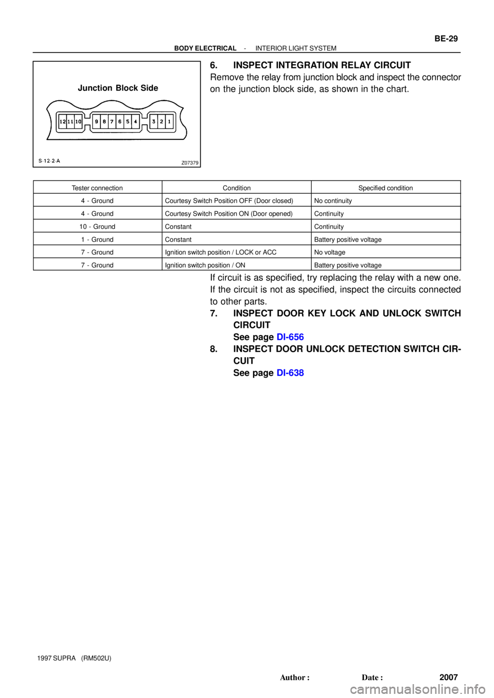
Z07379
Junction Block Side
- BODY ELECTRICALINTERIOR LIGHT SYSTEM
BE-29
2007 Author�: Date�:
1997 SUPRA (RM502U)
6. INSPECT INTEGRATION RELAY CIRCUIT
Remove the relay from junction block and inspect the connector
on the junction block side, as shown in the chart.
Tester connectionConditionSpecified condition
4 - GroundCourtesy Switch Position OFF (Door closed)No continuity
4 - GroundCourtesy Switch Position ON (Door opened)Continuity
10 - GroundConstantContinuity
1 - GroundConstantBattery positive voltage
7 - GroundIgnition switch position / LOCK or ACCNo voltage
7 - GroundIgnition switch position / ONBattery positive voltage
If circuit is as specified, try replacing the relay with a new one.
If the circuit is not as specified, inspect the circuits connected
to other parts.
7. INSPECT DOOR KEY LOCK AND UNLOCK SWITCH
CIRCUIT
See page DI-656
8. INSPECT DOOR UNLOCK DETECTION SWITCH CIR-
CUIT
See page DI-638