Page 22 of 1807

MT06N-01
D01920
Shift Lever Knob
Upper Console Panel
Shift Lever Boot
RetainerShift Lever Retainer
Shift and Select Lever
Boot No.1
x5
Service Hole
Cover
Starter
Pipe Support Bracket
Service Hole Cover
Ground Cable
Engine Under Cover
Oxygen SensorExhaust Front Pipe Exhaust Tail Pipe Exhaust Center PipePropeller ShaftCrossmember Brace
Heat Insulator Engine Rear
Mounting
Adjusting Washer BushingTransmission Shift Lever
Clutch Release Cylinder
N´m (kgf´cm, ft´lbf)Shift and Select Lever
Boot No.2
Oxygen Sensor Cover
: Specified torqueRear Engine Mounting
Member
� Non-reusable part� Gasket
�
� Gasket
� Gasket��
� Gasket
19 (195, 14)�
72 (730, 53)
12 (120, 9)
79 (805, 58)
49 (500, 36)
19 (195, 14)�
56 (570, 41)
12 (120, 9)
37 (380, 27)
12 (120, 9)
25 (260, 19)13 (135, 10)
39 (400, 29)
5.5 (55, 48 in.´lbf)
13 (130, 9)
13 (130, 9)
5.5 (55, 48 in.´lbf)
Heat Insulator72 (730, 53)
39 (400, 29)
25 (250, 18)19 (195, 14)
19 (195, 14)
7.8 (80, 69 in.´lbf)�
Bushing
�
19 (195, 14)
Normal Roof:
Sport Roof:
58 (590, 43)�
Transmission
Crossmember
Brace
20 (200, 14)
25 (250, 18)
�
58 (590, 43)�
MT-2
- MANUAL TRANSMISSION (V160)MANUAL TRANSMISSION UNIT
1570 Author�: Date�:
1997 SUPRA (RM502U)
MANUAL TRANSMISSION UNIT
COMPONENTS
Page 24 of 1807
MANUAL TRANSMISSION UNIT
1572 Author�: Date�:
1997 SUPRA (RM502U)
7. REMOVE EXHAUST CENTER PIPE
(a) Remove the 4 nuts and 2 gaskets.
Torque: 19")
Q04128
Q06366
Q04133
MT-4
- MANUAL TRANSMISSION (V160)MANUAL TRANSMISSION UNIT
1572 Author�: Date�:
1997 SUPRA (RM502U)
7. REMOVE EXHAUST CENTER PIPE
(a) Remove the 4 nuts and 2 gaskets.
Torque: 19 N´m (195 kgf´cm, 14 ft´lbf)
(b) Disconnect the exhaust center pipe from the 2 rings.
(c) Remove the exhaust center pipe.
8. REMOVE HEAT INSULATOR
Remove the 4 nuts and heat insulator.
Torque: 5.4 N´m (55 kgf´cm, 48 in.´lbf)
9. REMOVE CROSSMEMBER BRACE
Remove the 4 bolts (Normal Roof) or 6 bolts (Sport Roof) and
crossmember brace.
Torque: 13 N´m (130 kgf´cm, 9 ft´lbf)
10. REMOVE PROPELLER SHAFT
(See page PR-2)
11. REMOVE TRANSMISSION SHIFT LEVER
(a) Remove the bolt and nut.
(b) Remove the transmission shift lever, inside the vehicle.
Torque: 19 N´m (195 kgf´cm, 14 ft´lbf)
12. REMOVE CLUTCH RELEASE CYLINDER AND
GROUND CABLE
(a) Remove the bolt, clamp and ground cable.
Torque: 72 N´m (730 kgf´cm, 53 ft´lbf)
(b) Remove the 2 bolts and clutch release cylinder.
Torque: 12 N´m (120 kgf´cm, 9 ft´lbf)
13. DISCONNECT STARTER WIRE
(a) Remove the nut and disconnect the starter wire.
(b) Disconnect the starter wire connector.
14. DISCONNECT VEHICLE SPEED SENSOR AND
BACK-UP LIGHT SWITCH CONNECTORS
Page 34 of 1807

(h) Using SST, torque the adjust nut.
SST 09922-10010
Torque: 50 N´m (515 kgf´cm, 37 ft´lbf)
HI")
R06864
SST
- PROPELLER SHAFTPROPELLER SHAFT ASSEMBLY
PR-13
1686 Author�: Date�:
1997 SUPRA (RM502U)
(h) Using SST, torque the adjust nut.
SST 09922-10010
Torque: 50 N´m (515 kgf´cm, 37 ft´lbf)
HINT:
Use torque wrench with a fulcrum length of 34.5 cm (13.6 in.).
3. ADJUST PROPELLER SHAFT JOINT ANGEL (See
page PR-14)
NOTICE:
The joint angle should be checked when the propeller shaft
is removed and installed.
4. NORMAL ROOF:
INSTALL CENTER FLOOR CROSSMEMBER BRACE
Install the center floor crossmember brace and 4 bolts.
Torque: 13 N´m (130 kgf´cm, 9 ft´lbf)
5. SPORT ROOF:
INSTALL CENTER FLOOR CROSSMEMBER BRACE
Install the center floor crossmember brace and 6 bolts.
Torque: 13 N´m (130 kgf´cm, 9 ft´lbf)
6. INSTALL HEAT INSULATOR
Install the heat insulator and torque the 4 nuts.
Torque: 5.4 N´m (55 kgf´cm, 48 in.´lbf)
7. INSTALL EXHAUST PIPE (See page EM-94)
8. INSTALL OXYGEN SENSOR
Install the oxygen sensor with heat insulator and torque the 2
nuts.
Torque: 44 N´m (450 kgf´cm, 34 in.´lbf)
Page 41 of 1807

REMOVAL
1. REMOVE OXYGEN SENSOR
(a) Remove the 2 bolts.
(b) Remove the oxyge")
PR06V-01
R06868
R07621
Matchmarks PR-4
- PROPELLER SHAFTPROPELLER SHAFT ASSEMBLY
1677 Author�: Date�:
1997 SUPRA (RM502U)
REMOVAL
1. REMOVE OXYGEN SENSOR
(a) Remove the 2 bolts.
(b) Remove the oxygen sensor and heat insulator.
2. REMOVE EXHAUST PIPE (See page EM-94)
3. REMOVE HEAT INSULATOR
Remove the 4 nuts and heat insulator.
4. NORMAL ROOF:
REMOVE CENTER FLOOR CROSSMEMBER BRACE
Remove the 4 bolts and crossmember brace.
5. SPORT ROOF:
REMOVE CENTER FLOOR CROSSMEMBER BRACE
Remove the 6 bolts and crossmember brace.
6. 2JZ-GE:
REMOVE PROPELLER SHAFT
(a) Remove the 2 center support bearing set bolts and ad-
justing washers.
HINT:
Production vehicles are not equipped with adjusting washers.
NOTICE:
When removing the set bolts, support the center support
bearing by hand so that the transmission and intermediate
shaft, and propeller shaft and differential, remain in a
straight line.
(b) Place matchmarks on the differential companion flange
and flexible coupling.
(c) Remove the 3 bolts inserted in the differential companion
flange.
NOTICE:
The bolts inserted in the propeller shaft companion flange
should not be removed.
Page 76 of 1807

B01402
Sensor Side
ECU Side
IN0378
Sensor SideECU Side
IN0380
Sensor SideECU Side
IN0381
Pull Lightly
Looseness of Crimping
- INTRODUCTIONHOW TO TROUBLESHOOT ECU CONTROLLED
SYSTEMSIN-29
29 Author�: Date�:
1997 SUPRA (RM502U)
2. CONTINUITY CHECK (OPEN CIRCUIT CHECK)
(a) Disconnect the connectors at both ECU and sensor
sides.
(b) Measure the resistance between the applicable terminals
of the connectors.
Resistance: 1 W or less
HINT:
� Measure the resistance while lightly shaking the wire har-
ness vertically and horizontally.
�When tester probes are inserted into a connector, insert
the probes from the back. For waterproof connectors in
which the probes cannot be inserted from the back, be
careful not to bend the terminals when inserting the tester
probes.
3. RESISTANCE CHECK (SHORT CIRCUIT CHECK)
(a) Disconnect the connectors at both ends.
(b) Measure the resistance between the applicable terminals
of the connectors and body ground. Be sure to carry out
this check on the connectors on both ends.
Resistance: 1 MW or higher
HINT:
Measure the resistance while lightly shaking the wire harness
vertically and horizontally.
4. VISUAL CHECK AND CONTACT PRESSURE CHECK
(a) Disconnect the connectors at both ends.
(b) Check for rust or foreign material, etc. in the terminals of
the connectors.
(c) Check crimped portions for looseness or damage and
check if the terminals are secured in lock portion.
HINT:
The terminals should not come out when pulled lightly.
(d) Prepare a test male terminal and insert it in the female ter-
minal, then pull it out.
NOTICE:
When testing a gold-plated female terminal, always use a
gold-plated male terminal.
HINT:
When the test terminal is pulled out more easily than others,
there may be poor contact in that section.
Page 86 of 1807
38SUPRAÐNEW FEATURES
2. Sound Absorbing Materials
�Seal material has been newly provided to the bottom of the front pillar, and a quarter service hole cover has been
newly provided to the quarter portion in order to reduce road noise while driving.
�The material of sound absorbing material used in the roof side inner garnish, quarter trim, deck side trim and deck
rear trim has been changed to reduce road noise.
� CRUISE CONTROL SYSTEM
1. Actuator
The '97 Supra has adopted a new motor type actuator that is both lightweight and simple in construction.
The basic construction and operation of this actuator are the same as in the '96 4Runner with 5VZ±FE engine.
For details, see the 1996 4Runner New Car Features (Pub. No. NCF126U), page 71.
2. Cruise Control ECU
Manual Cancel Function
The manual cancel function, which cancels the cruise control when the parking brake is operated, has been
discontinued.
Page 87 of 1807
38SUPRAÐNEW FEATURES
3. Sound Absorbing Materials
�Seal material has been newly provided to the bottom of the front pillar, and a quarter service hole cover has been
newly provided to the quarter portion in order to reduce road noise while driving.
�The material of sound absorbing material used in the roof side inner garnish, quarter trim, deck side trim and deck
rear trim has been changed to reduce road noise.
� CRUISE CONTROL SYSTEM
1. Actuator
The '97 Supra has adopted a new motor type actuator that is both lightweight and simple in construction.
The basic construction and operation of this actuator are the same as in the '96 4Runner with 5VZ±FE engine.
For details, see the 1996 4Runner New Car Features (Pub. No. NCF126U), page 71.
2. Cruise Control ECU
Manual Cancel Function
The manual cancel function, which cancels the cruise control when the parking brake is operated, has been
discontinued.
Page 100 of 1807
24
:New :Discontinued SUPRAÐMODEL CODE & MODEL LINE±UP
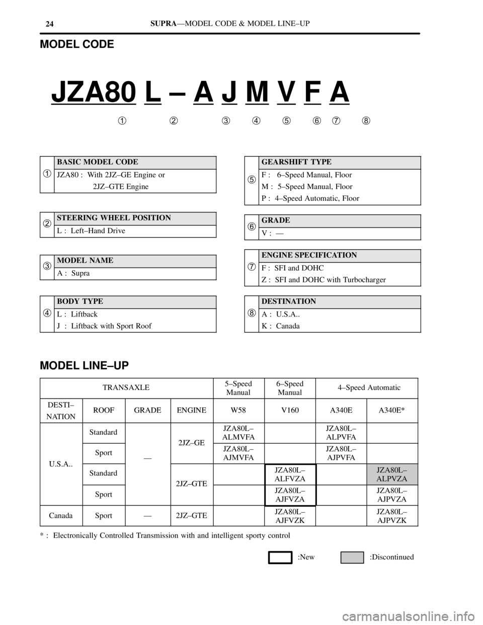
MODEL CODE
JZA80 L ± A J M V F A
��������������������������
�
�
BASIC MODEL CODE
�JZA80 : With 2JZ±GE Engine or
2JZ±GTE Engine
�STEERING WHEEL POSITION�L : Left±Hand Drive
�MODEL NAME�A : Supra
BODY TYPE
�L : Liftback
J : Liftback with Sport Roof
GEARSHIFT TYPE
�F : 6±Speed Manual, Floor
M : 5±Speed Manual, Floor
P : 4±Speed Automatic, Floor
�GRADE�V : Ð
ENGINE SPECIFICATION
�F : SFI and DOHC
Z : SFI and DOHC with Turbocharger
DESTINATION
A : U.S.A..
K : Canada
MODEL LINE±UP
TRANSAXLE5±Speed
Manual6±Speed
Manual 4±Speed Automatic
DESTI±ROOFGRADEENGINEW58V160A340EA340E*NATIONROOFGRADEENGINEW58V160A340EA340E*
Standard
2JZ GE
JZA80L±
ALMVFAJZA80L±
ALPVFA
USA
SportÐ
2JZ±GEJZA80L±
AJMVFAJZA80L±
AJPVFA
U.S.A..
Standard
2JZ±GTE
JZA80L±
ALFVZAJZA80L±
ALPVZA
Sport
2JZ±GTEJZA80L±
AJFVZAJZA80L±
AJPVZA
CanadaSportÐ2JZ±GTEJZA80L±
AJFVZKJZA80L±
AJPVZK
* : Electronically Controlled Transmission with and intelligent sporty control