Page 436 of 1807
BO6850
BO6850mm (in.) Imaginary
Standard
Line
(Two-Dimensional Distance)
Imaginary
Standard
Line
(Three-Dimensional Distance)
Symbol Name Hole dia. Symbol Name Hole dia.
A, a Steering gear box installation hole front 12 (0.47) E, e Lower arm installation hole-front25y16
(0.98y0.63)
B, b Upper arm installation hole front 14 (0.55) F, f Lower arm installation hole rear25y16
(0.98y0.63)
C, cSuspension crossmember installation
hole front-lower15 (0.59) G, g Upper arm installation hole rear 14 (0.55)
D, dSteering gear box installation hole-
lower12 (0.47) H, hSuspension crossmember installation
hole rear-lowerRH 15y13
(0.59 x 0.51)
LH 13 (0.51)
FRONT SUSPENSION CROSSMEMBER
BODY DIMENSIONSDI-10
Page 437 of 1807
mm (in.)BO8851
BO6851
Imaginary
Standard
Line
(Two-Dimensional Distance)
Imaginary
Standard
Line
(Three-Dimensional Distance)
Symbol Name Hole dia. Symbol Name Hole dia.
I, iSuspension crossmember installation
hole front-lower18 (0.71) L, lSuspension crossmember installation
hole rear-lower18 (0.71)
J, j Lower arm installation hole-front30y16
(1.18y0.63)M, mSuspension crossmember installation
hole rear-lower18 (0.71)
K, k Lower arm installation hole rear30y16
(1.18 x 0.63)
FRONT SUSPENSION CROSSMEMBER (Cont'd)
BODY DIMENSIONSDI-11
Page 440 of 1807

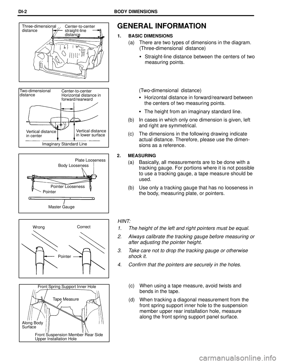
GENERAL INFORMATION
1. BASIC DIMENSIONS
(a) There are two types of dimensions in the diagram.
(Three-dimensional distance)
�Straight-line distance between the centers of two
measuring points.
(Two-dimensional distance)
�Horizontal distance in forward/rearward between
the centers of two measuring points.
�The height from an imaginary standard line.
(b) In cases in which only one dimension is given, left
and right are symmetrical.
(c) The dimensions in the following drawing indicate
actual distance. Therefore, please use the dimen-
sions as a reference.
2. MEASURING
(a) Basically, all measurements are to be done with a
tracking gauge. For portions where it is not possible
to use a tracking gauge, a tape measure should be
used.
(b) Use only a tracking gauge that has no looseness in
the body, measuring plate, or pointers.
HINT:
1. The height of the left and right pointers must be equal.
2. Always calibrate the tracking gauge before measuring or
after adjusting the pointer height.
3. Take care not to drop the tracking gauge or otherwise
shock it.
4. Confirm that the pointers are securely in the holes.
(c) When using a tape measure, avoid twists and
bends in the tape.
(d) When tracking a diagonal measurement from the
front spring support inner hole to the suspension
member upper rear installation hole, measure
along the front spring support panel surface.
Center-to-center
straight-line
distance Three-dimensional
distance
Front Spring Support Inner Hole
Tape Measure
Along Body
Surface
Front Suspension Member Rear Side
Upper Installation HoleMaster Gauge PointerPointer LoosenessBody LoosenessPlate Looseness Two-dimensional
distanceCenter-to-center
Horizontal distance in
forward/rearward
Vertical distance
in lower surface Vertical distance
in center
Imaginary Standard Line
WrongCorrect
Pointer
BODY DIMENSIONSDI-2
Page 475 of 1807
NO8909
NO8909mm (in.) Imaginary
Standard
Line
(Three-Dimensional Distance)
Symbol Name Hole dia. Symbol Name Hole dia.
A, a Strut rod installation hole-inner14.2
(0. 559)F, f No. 2 lower arm installation hole-front26y14.2
(1.02y0.559)
B, b Differential carrier installation nut12 (0.47)
nutG, g Rear suspension member standard hole 20 (0.79)
C, c Rear suspension member standard hole 20 (0.79) H, h Upper arm installation hole-rear14.2
(0.559)
D, d No. 1 lower arm installation hole-front26x 14.2
(1.02y0.559)I, i No. 2 lower arm installation hole-rear26y14.2
(1.02y0.559)
E, eUpper arm installation hole-front14.2
(0.559)
REAR SUSPENSION CROSSMEMBER
BODY DIMENSIONSDI-12
Page 476 of 1807
mm (in.)NO8909
NO8909
Imaginary
Standard
Line
(Two-Dimensional Distance)
Symbol Name Hole dia. Symbol Name Hole dia.
A, a Strut rod installation hole-inner14.2
(0.559)F, f No. 2 lower arm installation hole-front26y14.2
(1.02y0.559)
B, b Differential carrier installation nut12 (0.47)
nutG, g Rear suspension member standard hole20 (0.79)
C, c Rear suspension member standard hole 20 (0.79) H, h Upper arm installation hole-rear14.2
(0.559)
D, d No. 1 lower arm installation hole-front26y14.2
(1.02y0.559)I, i No. 2 lower arm installation hole-rear26y14.2
(1.02y0.559)
E, e Upper arm installation hole-front14.2
(0.559)
REAR SUSPENSION CROSSMEMBER (Cont'd)
BODY DIMENSIONSDI-13
Page 504 of 1807

FOR THE TOYOTA DEALER
COLLISION REPAIR INFORMATION
TITLE: TOYOTA COLLISION REPAIR & PAGE 1 of 5
REFINISH SERVICE PUBLICATIONS
SECTION: GENERAL INFORMATION BULLETIN #75
MODELS: ALL
DATE: JANUARY 1997
Toyota Collision Repair and Refinish Service Publications are an integral part of the Toyota
philosophy of ªfix it right the first timeº. This detailed repair information is designed to
speed and simplify repair operations and improve the quality of each repair. For ordering
information, please refer to page 5 of this bulletin.
COLLISION REPAIR MANUALS
�Cutting and welding operations�Anti±rust treatment
�Body component diagrams and illustrations�SRS handling precautions
�Body panel replacement�Electronic control unit (ECU) locations
�Body dimensions�Plastic body part identification
Model
YearPart NumberPrice
AVALON
Collision Repair Manual 1997±95 00400±BR046 $20.00
CAMRY
Collision Repair Manual 1997 00400±BR062 20.00
Collision Repair Manual 1996±92 00400±BR032 9.00
Collision Repair Manual±Coupe 1996±94 00400±BR043 9.00
Collision Repair Manual±Wagon 1996±92 00400±BR035 9.00
Collision Repair Manual 1991±87 00400±BRM01±0E 8.95
Collision Repair Manual 1986±83 00400±36433±E 6.95
CELICA
Collision Repair Manual±Convertible 1997±94 00400±BR048 15.00
Collision Repair Manual 1997±94 00400±BR044 15.00
Collision Repair Manual 1993±90 00400±BR022 6.95
Collision Repair Manual 1989±86 00400±BRM00±1E 8.95
COROLLA
Collision Repair Manual 1997±93 00400±BR038 15.00
Collision Repair Manual±Sedan 1992±87 00400±BR012 6.95
Collision Repair Manual±All Trac 1992±88 00400±BR014 4.95
Collision Repair Manual±Wagon 1992±88 00400±BR013 4.95
Collision Repair Manual±FX 1988±87 00400±BRM00±6E 4.95
Collision Repair Manual±FF/FR 1987±83 00400±36434±E 6.95
(Front Wheel Drive/Rear Wheel Drive)
Page 507 of 1807

PRICES SUBJECT TO CHANGE WITHOUT NOTICEORDERING INFORMATION ON PAGE 5
TOYOTA COLLISION REPAIR & REFINISH PAGE 4 of 5
SERVICE PUBLICATIONS (cont'd)
COLLISION REPAIR INFORMATION BULLETINS
Collision Repair Information Bulletins (CRIBS) provide Toyota body and paint technicians
with the latest developments in collision repair and refinish. Information is divided among
the following topics:
�General information�Interior
�Structural repair�Electrical
�Welding�Alignment
�Refinish�Tools and equipment
�Exterior
Name
Part NumberPrice
Collision Repair Information Binder
includes Bulletins #1±41 00408±03000±01 $20.00
CRIB Bulletin #49 00408±03000±49 1.00
CRIB Bulletins #51±57 00408±03000±51±57 10.00
CRIB Bulletins #58±61 00408±03000±58±61 5.00
CRIB Bulletins #62±65 00408±03000±62±65 5.00
CRIB Bulletins #66±67 00408±03000±66±67 5.00
CRIB Bulletins #68±69 00408±03000±68±69 1.18
CRIB Bulletin #70 00408±03000±70 2.00
CRIB Bulletin #71 00408±03000±71 2.24
CRIB Bulletin #72 00408±03000±72 1.62
BODY DIMENSIONS GUIDE
The Toyota Body Dimension Guide provides data necessary to assess the extent of
collision damage by using vehicle±specific dimension charts and measurement
specifications. The dimension guide provides specifications for the following areas:
�engine compartment�suspension crossmember
�door and compartment openings�frame alignment
�underbody�cab alignment
1980±1997 Body Dimension Guide 00117±00540±97 $3.50
Page 509 of 1807
NO8908
(Three-Dimensional Distance)
Imaginary
Standard
Line
mm (in.)
Hole dia.
10 (0.39)
18 (0.71)
14 (0.55)nut
10 (0.39)nut
18 (0.71)
10 (0.39)nut
12 (0. 47)nut Name
Front floor reinforcement standard hole
Rear floor side member standard hole
Rear suspension member installation nut
Suspension member bracket installation nut-front, outer
Rear floor side member rear standard hole
Tank band installation nut
Transport hook installation nut Symbol
L, l
M, m
N, n
P, p
Q, q
R Hole dia.
7 (0.28)
9 (0.35)
18 (0.71)
13 (0.51)
14 (0.55) nut
18 (0.71)
10 (0.39) nut
10(0.39) nut Name
Font side member standard hole
Font crossmember working hole
Font side member standard hole
Font suspension crossmember installation hole
Front suspension crossmember installation nut
Front side member standard hole
Engine rear mounting member installation nut-front
Propeller shaft center support bearing installation nut Symbol
A, a
B, b
D, d
F, f
H, h
I, i
J, j
K, k
UNDER BODY
r
BODY DIMENSIONSDI-8