Page 53 of 1807

(l) Observe the following precautions to avoid damage to the
fol")
IN0253
WRONG CORRECT
IN0252
WRONG CORRECT
IN0002
Example IN-6
- INTRODUCTIONREPAIR INSTRUCTIONS
6 Author�: Date�:
1997 SUPRA (RM502U)
(l) Observe the following precautions to avoid damage to the
following parts:
(1) Do not open the cover or case of the ECU, ECM,
PCM or TCM unless absolutely necessary. (If the IC
terminals are touched, the IC may be destroyed by
static electricity.)
(2) To disconnect vacuum hoses, pull on the end, not
the middle of the hose.
(3) To pull apart electrical connectors, pull on the con-
nector itself, not the wires.
(4) Be careful not to drop electrical components, such
as sensors or relays. If they are dropped on a hard
floor, they should be replaced and not reused.
(5) When steam cleaning an engine, protect the elec-
tronic components, air filter and emissions-related
components from water.
(6) Never use an impact wrench to remove or install
temperature switches or temperature sensors.
(7) When checking continuity at the wire connector, in-
sert the tester probe carefully to prevent terminals
from bending.
(8) When using a vacuum gauge, never force the hose
onto a connector that is too large. Use a step-down
adapter for adjustment. Once the hose has been
stretched, it may leak.
(m) Tag hoses before disconnecting them:
(1) When disconnecting vacuum hoses, use tags to
identify how they should be reconnected.
(2) After completing a job, double check that the vacu-
um hoses are properly connected. A label under the
hood shows the proper layout.
(n) Unless otherwise stated, all resistance is measured at an
ambient temperature of 20°C (68°F). Because the resis-
tance may be outside specifications if measured at high
temperatures immediately after the vehicle has been run-
ning, measurements should be made when the engine
has cooled down.
Page 83 of 1807
 HO2S
Heated Oxygen SensorHeated Oxygen Sensor (HO2S)
IACIdle Air ControlIdle Speed Control (ISC)
IATIntake Air TemperatureIntake or I")
IN-36
- INTRODUCTIONTERMS
36 Author�: Date�:
1997 SUPRA (RM502U) HO2S
Heated Oxygen SensorHeated Oxygen Sensor (HO2S)
IACIdle Air ControlIdle Speed Control (ISC)
IATIntake Air TemperatureIntake or Inlet Air Temperature
ICMIgnition Control Module-
IFIIndirect Fuel InjectionIndirect Injection
IFSInertia Fuel-Shutoff-
ISCIdle Speed Control-
KSKnock SensorKnock Sensor
MAFMass Air FlowAir Flow Meter
MAPManifold Absolute PressureManifold Pressure
Intake Vacuum
MCMixture Control
Electric Bleed Air Control Valve (EBCV)
Mixture Control Valve (MCV)
Electric Air Control Valve (EACV)
MDPManifold Differential Pressure-
MFIMultiport Fuel InjectionElectronic Fuel Injection (EFI)
MILMalfunction Indicator LampCheck Engine Light
MSTManifold Surface Temperature-
MVZManifold Vacuum Zone-
NVRAMNon-V olatile Random Access Memory-
O2SOxygen SensorOxygen Sensor, O2 Sensor (O2S)
OBDOn-Board DiagnosticOn-Board Diagnostic (OBD)
OCOxidation Catalytic ConverterOxidation Catalyst Converter (OC), CCo
OPOpen LoopOpen Loop
PAIRPulsed Secondary Air InjectionAir Suction (AS)
PCMPowertrain Control Module-
PNPPark/Neutral Position-
PROMProgrammable Read Only Memory-
PSPPower Steering Pressure-
PTOXPeriodic Trap OxidizerDiesel Particulate Filter (DPF)
Diesel Particulate Trap (DPT)
RAMRandom Access MemoryRandom Access Memory (RAM)
RMRelay Module-
ROMRead Only MemoryRead Only Memory (ROM)
RPMEngine SpeedEngine Speed
SCSuperchargerSupercharger
SCBSupercharger Bypass-
SFISequential Multiport Fuel InjectionElectronic Fuel Injection (EFI), Sequential Injection
SPLSmoke Puff Limiter-
SRIService Reminder Indicator-
SRTSystem Readiness Test-
STScan Tool-
TBThrottle BodyThrottle Body
TBIThrottle Body Fuel InjectionSingle Point Injection
Central Fuel Injection (Ci)
TCTurbochargerTurbocharger
TCCTorque Converter ClutchTorque Converter
Page 237 of 1807

Check if there is any scratch and b")
6
Radio
POOR RECEPTION
Is the condition bad in comparison with other vehicle?
Are there any additional installation parts?
(Sun shade film, telephone antenna, etc.)
Check if there is any scratch and breaking of a wire on
the glass antenna and the defogger pattern.
(visual check. tester)
(See page BE-56)
Is the contact of the plug jack of the radio OK?
Does the condition get better by using the outer
antenna (such as pillar antenna)?
Is the contact of the antenna terminal on the glass
surface and the defogger terminal?
Is the continuity of the antenna cord OK?
Check the grounding of the antenna, antenna cord,
choke coil, and noise filter. (See page BE-72)
Does the condition get better by exchanging
the choke coil?
Does the condition get better by exchanging the
antenna cord?Take a measure for contact. An electric wave environment.
Does the condition get better if removing
them?
Influence of additional installation parts.
Influence of the sun shade film.
Repair. (See page BE-56)
Check the radio.
Take a measure for contact.
Grounding failure. Exchange the antenna cord.
Exchange the choke coil.
Exchange the antenna cord. Ye s
No
Exchange the glass.Ye s
Ye s
Ye s
Ye s
Ye s
Ye s
Ye s
Ye s No
No
No
NoNo
No
No
No
NG
OK
- BODY ELECTRICALAUDIO SYSTEM
BE-81
2059 Author�: Date�:
1997 SUPRA (RM502U)
Page 568 of 1807
MA0688
Outside
Inside
- DIAGNOSTICSENGINE (2JZ-GTE)
DI-153
381 Author�: Date�:
1997 SUPRA (RM502U)
4 Check are filter.
PREPARATION:
Remove air filter.
CHECK:
Visually check that the air cleaner element is not dirty or exces-
sively oily.
HINT:
If necessary, clean element with compressed air. First blow from
inside throughly, then blow from outside of element.
NG Repair or replace.
OK
5 Check idle speed.
PREPARATION:
(a) Warm up engine to normal operating temperature.
(b) Switch off all accessories.
(c) Switch off air conditioning.
(d) Shift transmission into ºNº position.
(e) Connect the OBD II scan tool or TOYOTA hand-held tester to DLC3 on the vehicle.
CHECK:
Use CURRENT DATA to check the engine idle speed.
OK:
Idle speed: 650 ± 50 rpm
NG Proceed to matrix chart of problem symptoms
on page DI-169.
OK
Page 617 of 1807
DI-202
- DIAGNOSTICSENGINE (2JZ-GTE)
430 Author�: Date�:
1997 SUPRA (RM502U)
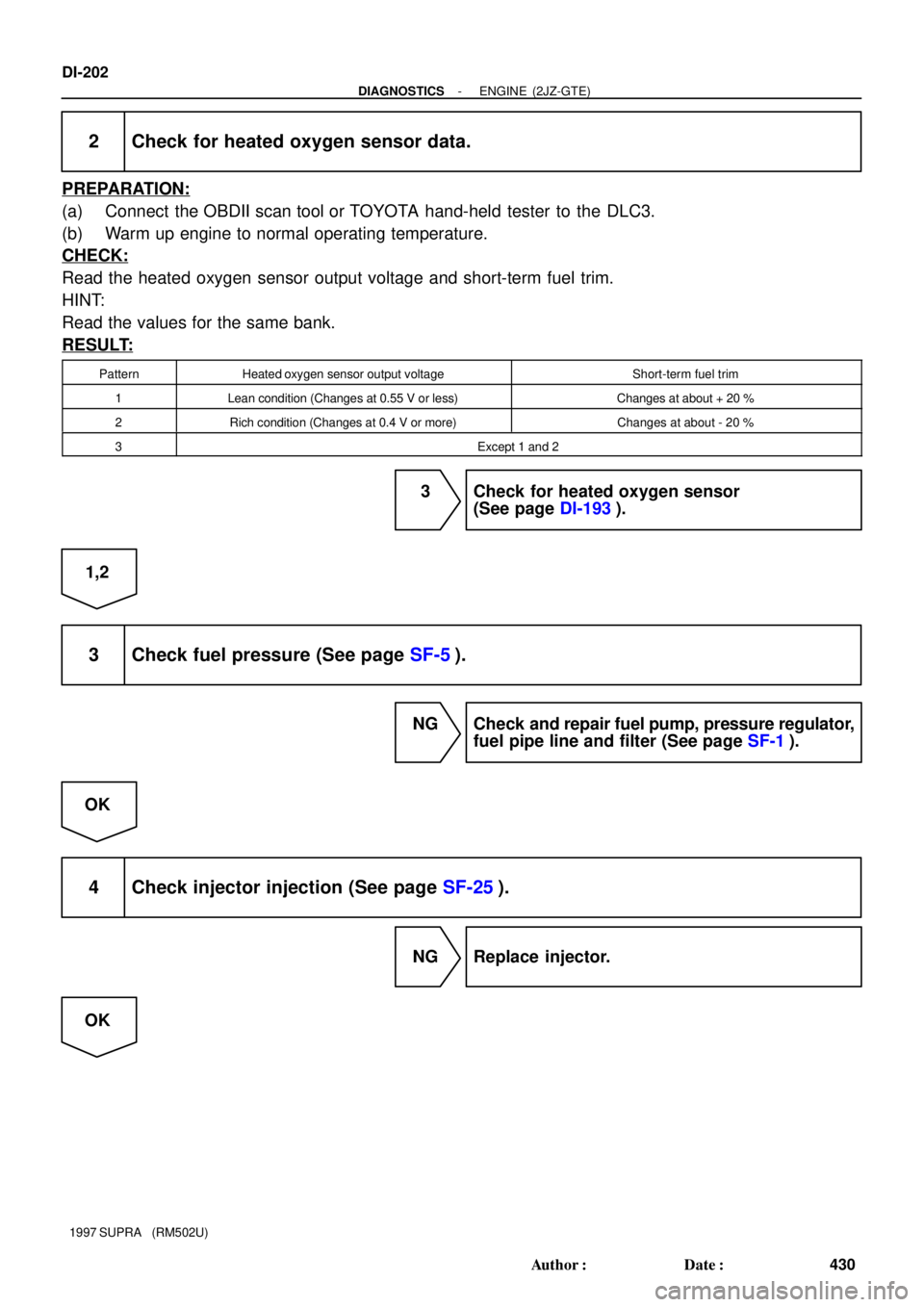
2 Check for heated oxygen sensor data.
PREPARATION:
(a) Connect the OBDII scan tool or TOYOTA hand-held tester to the DLC3.
(b) Warm up engine to normal operating temperature.
CHECK:
Read the heated oxygen sensor output voltage and short-term fuel trim.
HINT:
Read the values for the same bank.
RESULT:
PatternHeated oxygen sensor output voltageShort-term fuel trim
1Lean condition (Changes at 0.55 V or less)Changes at about + 20 %
2Rich condition (Changes at 0.4 V or more)Changes at about - 20 %
3Except 1 and 2
3 Check for heated oxygen sensor
(See page DI-193).
1,2
3 Check fuel pressure (See page SF-5).
NG Check and repair fuel pump, pressure regulator,
fuel pipe line and filter (See page SF-1).
OK
4 Check injector injection (See page SF-25).
NG Replace injector.
OK
Page 622 of 1807
A00700
ON
Check Harness A
ECM
B20, 19, 18, 17, 16, 15
#10
(+)#20
(+)#30
(+)#40
(+)#50
(+)#60
(+)
- DIAGNOSTICSENGINE (2JZ-GTE)
DI-207
435 Author�: Date�:
1997 SUPRA (RM502U)
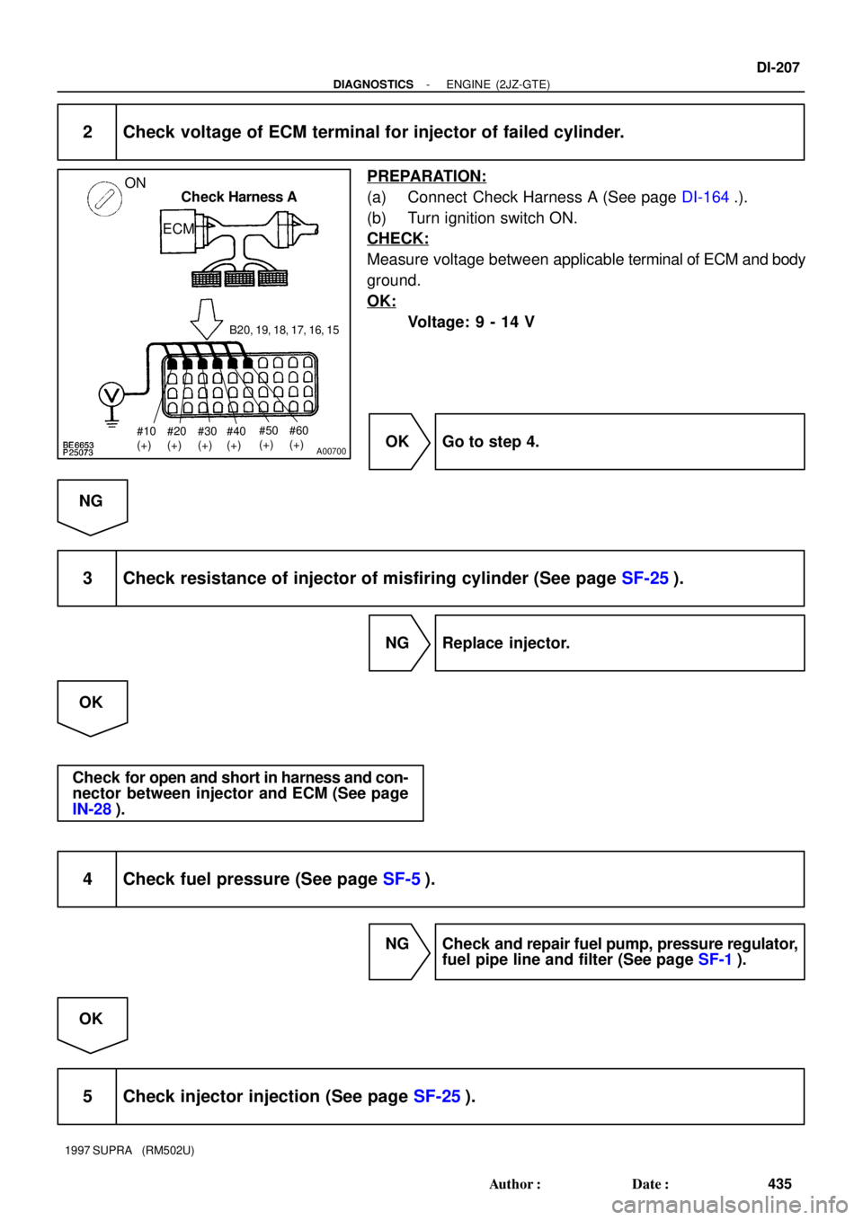
2 Check voltage of ECM terminal for injector of failed cylinder.
PREPARATION:
(a) Connect Check Harness A (See page DI-164.).
(b) Turn ignition switch ON.
CHECK:
Measure voltage between applicable terminal of ECM and body
ground.
OK:
Voltage: 9 - 14 V
OK Go to step 4.
NG
3 Check resistance of injector of misfiring cylinder (See page SF-25).
NG Replace injector.
OK
Check for open and short in harness and con-
nector between injector and ECM (See page
IN-28).
4 Check fuel pressure (See page SF-5).
NG Check and repair fuel pump, pressure regulator,
fuel pipe line and filter (See page SF-1).
OK
5 Check injector injection (See page SF-25).
Page 684 of 1807
BE6653S03252S03253
A03147
ON
Air
Air
FE
F
VSV: OFF VSV: ONE
Air Filter
- DIAGNOSTICSENGINE (2JZ-GTE)
DI-269
497 Author�: Date�:
1997 SUPRA (RM502U)
5 Connect the TOYOTA hand-held tester and check operation of VSV for intake air
control valve.
PREPARATION:
(a) Connect the TOYOTA hand-held tester to the DLC3.
(b) Turn ignition switch ON and TOYOTA hand-held tester
main switch ON.
(c) Select the ACTIVE TEST mode on the TOYOTA hand-
held tester.
CHECK:
Check operation of VSV when VSV is operated by the TOYOTA
hand-held tester.
OK:
VSV is ON:
Air from pipe E flows out through pipe F.
VSV is OFF:
Air does not flow from pipe E to pipe F.
OK Go to step 7.
NG
6 Check VSV for intake air control valve (See page SF-61).
NG Replace VSV for intake air control valve.
OK
Page 685 of 1807
BE6653S03254S03255
A03148
ON
Air
F
VSV: OFF VSV: ONE Air
E
Air Filter
DI-270
- DIAGNOSTICSENGINE (2JZ-GTE)
498 Author�: Date�:
1997 SUPRA (RM502U)
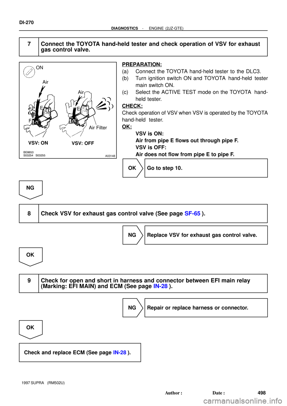
7 Connect the TOYOTA hand-held tester and check operation of VSV for exhaust
gas control valve.
PREPARATION:
(a) Connect the TOYOTA hand-held tester to the DLC3.
(b) Turn ignition switch ON and TOYOTA hand-held tester
main switch ON.
(c) Select the ACTIVE TEST mode on the TOYOTA hand-
held tester.
CHECK:
Check operation of VSV when VSV is operated by the TOYOTA
hand-held tester.
OK:
VSV is ON:
Air from pipe E flows out through pipe F.
VSV is OFF:
Air does not flow from pipe E to pipe F.
OK Go to step 10.
NG
8 Check VSV for exhaust gas control valve (See page SF-65).
NG Replace VSV for exhaust gas control valve.
OK
9 Check for open and short in harness and connector between EFI main relay
(Marking: EFI MAIN) and ECM (See page IN-28).
NG Repair or replace harness or connector.
OK
Check and replace ECM (See page IN-28).